EP1229556A2 - Elektrische Leitung - Google Patents
Elektrische Leitung Download PDFInfo
- Publication number
- EP1229556A2 EP1229556A2 EP02001819A EP02001819A EP1229556A2 EP 1229556 A2 EP1229556 A2 EP 1229556A2 EP 02001819 A EP02001819 A EP 02001819A EP 02001819 A EP02001819 A EP 02001819A EP 1229556 A2 EP1229556 A2 EP 1229556A2
- Authority
- EP
- European Patent Office
- Prior art keywords
- electrical line
- insulating material
- electrically insulating
- hook
- needle
- Prior art date
- Legal status (The legal status is an assumption and is not a legal conclusion. Google has not performed a legal analysis and makes no representation as to the accuracy of the status listed.)
- Granted
Links
Images


Classifications
-
- H—ELECTRICITY
- H05—ELECTRIC TECHNIQUES NOT OTHERWISE PROVIDED FOR
- H05K—PRINTED CIRCUITS; CASINGS OR CONSTRUCTIONAL DETAILS OF ELECTRIC APPARATUS; MANUFACTURE OF ASSEMBLAGES OF ELECTRICAL COMPONENTS
- H05K3/00—Apparatus or processes for manufacturing printed circuits
- H05K3/0058—Laminating printed circuit boards onto other substrates, e.g. metallic substrates
-
- B—PERFORMING OPERATIONS; TRANSPORTING
- B60—VEHICLES IN GENERAL
- B60R—VEHICLES, VEHICLE FITTINGS, OR VEHICLE PARTS, NOT OTHERWISE PROVIDED FOR
- B60R16/00—Electric or fluid circuits specially adapted for vehicles and not otherwise provided for; Arrangement of elements of electric or fluid circuits specially adapted for vehicles and not otherwise provided for
- B60R16/02—Electric or fluid circuits specially adapted for vehicles and not otherwise provided for; Arrangement of elements of electric or fluid circuits specially adapted for vehicles and not otherwise provided for electric constitutive elements
- B60R16/0207—Wire harnesses
-
- H—ELECTRICITY
- H01—ELECTRIC ELEMENTS
- H01B—CABLES; CONDUCTORS; INSULATORS; SELECTION OF MATERIALS FOR THEIR CONDUCTIVE, INSULATING OR DIELECTRIC PROPERTIES
- H01B7/00—Insulated conductors or cables characterised by their form
- H01B7/40—Insulated conductors or cables characterised by their form with arrangements for facilitating mounting or securing
-
- H—ELECTRICITY
- H05—ELECTRIC TECHNIQUES NOT OTHERWISE PROVIDED FOR
- H05K—PRINTED CIRCUITS; CASINGS OR CONSTRUCTIONAL DETAILS OF ELECTRIC APPARATUS; MANUFACTURE OF ASSEMBLAGES OF ELECTRICAL COMPONENTS
- H05K1/00—Printed circuits
- H05K1/02—Details
- H05K1/03—Use of materials for the substrate
- H05K1/0393—Flexible materials
-
- H—ELECTRICITY
- H05—ELECTRIC TECHNIQUES NOT OTHERWISE PROVIDED FOR
- H05K—PRINTED CIRCUITS; CASINGS OR CONSTRUCTIONAL DETAILS OF ELECTRIC APPARATUS; MANUFACTURE OF ASSEMBLAGES OF ELECTRICAL COMPONENTS
- H05K2201/00—Indexing scheme relating to printed circuits covered by H05K1/00
- H05K2201/20—Details of printed circuits not provided for in H05K2201/01 - H05K2201/10
- H05K2201/209—Auto-mechanical connection between a component and a PCB or between two PCBs
Definitions
- the invention relates to an electrical line with at least one electrical conductive material contained in at least one electrically insulating Material is embedded, as well as methods and arrangements for manufacturing such electrical lines.
- electrical cables are of the type mentioned at the beginning known.
- electrical lines can be considered flexible Ribbon cable (FFC) or as flexible printed circuits (FPC) his.
- FFC flexible Ribbon cable
- FPC flexible printed circuits
- Such electrical lines enter, for example the automotive industry, where they e.g. between a car roof or a car door and a mounting surface, in particular an interior paneling, which has a textile-like surface.
- the electrical lines are for example glued to the inner lining. It can however, the problem may arise that the adhesive is due to silicone oils, which are used in the production of the interior lining, is not reliably liable. Furthermore, glued electrical cables can be used do not dismantle without problems if, for example, auto parts, on which such electrical lines are laid to reduce waste a material separation and subsequent material recycling should be fed.
- the invention has for its object one in a vehicle compartment easy and inexpensive to lay electrical cable.
- it is an object of the invention, a method and a To provide an arrangement for producing such an electrical line.
- an electrical line with the features of claim 1 provided. It is characterized in that their surface, at least in some areas, directly and without an adhesive connection Velcro-type integrated in the electrically insulated material Has hooks and / or eyelets.
- hook and loop fastener Eyelets understood every structure that fixes like a Velcro fastener allows.
- structures can also be used as hooks serve in the form of harpoon tips, mushroom heads or the like.
- the electrically conductive material like a laminate between at least two layers of at least one electrically insulating material are embedded be, wherein at least one of the two layers by at least one in some areas with hook-and-loop hook-and-loop eyelets Structure is formed.
- a sandwich-like layer structure is particularly suitable for an electrical cable with a flat cross-section, such as for a flexible ribbon cable (FFC) or a flexible printed circuit (FPC).
- FFC flexible ribbon cable
- FPC flexible printed circuit
- At least one of the two layers advantageously has a plastic film or according to a further embodiment of the electrical Line a fabric material. Both materials are cheap in the manufacture and easy to process. In the simplest case, therefore an ordinary Velcro tape as an electrically insulating material serve. As mentioned in the beginning compared to conventional production electrical cables ordinary plastic foils or fabric materials only be replaced by those with hooks or eyes, there are no additional process steps in the production of the invention electrical conductor.
- One layer preferably has a hook and the other Layer a structure with eyelets. Both can do the same Layers are either hooks or eyelets. In both cases is a double-sided attachment of the invention electrical cable on appropriately trained interior panels or functional areas.
- the electrical line according to the invention can be a flexible ribbon cable (FFC) or a flexible printed circuit (FPC).
- FFC flexible ribbon cable
- FPC flexible printed circuit
- Conduction is the electrically insulating material, at least in some areas with a Velcro type hook or eyelet Structure provided with the electrically insulating material Fuses form.
- Such an electrical line is particularly special easy to manufacture if in the manufacturing process of electrical Line provided melting of the electrically insulating material is, as is the case for example in an extrusion device.
- the Melting of the electrically insulating material can then create a durable fusion between the one to be applied Structure and the electrically insulating material can be exploited. On additional adhesives can therefore be dispensed with.
- That kind of electrical Cable can be with a flat or round cross section realize.
- the hook and loop type hooks are made from the electrical insulating material itself. Since the hook is directly in the electrical insulating material is generated, no additional Structure with hooks on the surface of the electrical wire to be applied. This way the use of material reduced. At the same time, a low overall height of the electrical line can be retained since no material is additionally applied to the surface of the electrical line is applied. This kind of electrical too
- the cable can be used with either a flat or a round cross-section realize.
- Another object of the invention is a method for providing a Surface of an electrical cable with hook-and-loop fasteners or eyelets, in which at least one electrically conductive material in at least an electrically insulating material is embedded, the electrically insulating material at least in regions by at least a Velcro type hook or loop structure is formed becomes.
- a method of this type can be used, in particular, to achieve those according to the invention electrical lines of the first and second variant easy to implement.
- the electrically conductive material through a lamination process between at least two layers of at least one electrically insulating Embedded material, with at least one of the layers through an at least partially hook-and-loop type hook and loop having structure is formed.
- electrical cables with a flat cross section such as realize flexible ribbon cables or flexible printed circuits, which the above-mentioned advantages of the invention have electrical line of the first variant.
- This second variant of the invention The method is suitable for both electrical cables with flat Cross section as well as for electrical cables with a round cross section.
- the electrical lines produced by this method exhibit the advantages of the electrical lines described above the second variant.
- Another object of the invention is a method for providing a Surface of an electrical cable with hook-and-loop fasteners, in which at least one electrically conductive material in at least one electrically insulating material is embedded and at least in some areas Velcro-like directly in the electrically insulating material Hooks are formed.
- the so-called third variant can be electrical lines according to the invention third variant.
- needle-like structures in the electrically insulating material itself by means of a first structuring agent created needle-like structures.
- the needle-like structures can be generated by a first roller with a Surface area of the electrically insulating material in contact brought.
- the formation of needle-like structures in the electrical insulating material is a process that is simple perform and using the roller as a structuring agent particularly well in a continuous manufacturing process of the invention electrical line can be integrated.
- the needle-like structures are preferably formed at one temperature of the electrically insulating material, in which the electrically insulating Material is easily deformable. In this way, the needle-like Generate structures particularly easily.
- the tips of the needle-like structures are advantageously by means of a second structuring agent formed into hooks. Only by reshaping the needle-like structures into hooks becomes the surface the electrical line formed such that it together with a Mounting surface with eyelets has a Velcro fastener-like connection can come in.
- the tips of the needle-like structures are preferred by a to Longitudinal extension of the electrical line parallel relative movement of the electrical line bent or widened with respect to a second roller.
- a roller By using a roller to bend or widen the hook and the one for the longitudinal extension of the electrical line This forming process can also be carried out in parallel relative movement particularly easy in a continuous manufacturing process Integrate the third variant electrical line according to the invention.
- the tips of the needle-like are advantageously reshaped Structures after cooling the electrically insulating material to a temperature at which the needle-like structures solidify, whereby the second structuring means one for deforming the electrical insulating material has the required temperature. In this way it can be ensured that only the tips of the needle-like Structures are reshaped and due to the needle-like structures easy deformability due to temperature not completely deformed become.
- the method of the second and third variant is at least one electrically conductive strand of material in an extrusion device with provided at least one plastic jacket. Isolating one electrically conductive material in an extrusion device is a continuous process that works particularly well with the structuring process variant 2 and 3 can be combined.
- Procedure of variants 2 and 3 is done by the electrical Line with the Velcro type hooks or eyes immediately after the emergence of the electrical line from an extrusion device.
- the elevated temperature which is the electrically insulating Has material on leaving the extrusion device, directly to Establishing a fused connection between the electrically insulating Material and a structure with hooks or eyes or for Generate needle-like structures in the electrically insulating material exploited. An additional process step for heating the electrical insulating material can thus be saved.
- Another object of the invention is an arrangement for application a structure with hook and loop fasteners in at least one surface area of an electrical line, with a Extrusion device for providing at least one electrically conductive Material strand with at least one plastic sheathing and one arranged in the exit area of the extrusion device Pressure roller for pressing one on its electrical line Velcro-type hooks or eyelets on the opposite side Structure to the electrical line, the electrical line with the Structure of a fusion bond.
- a Extrusion device for providing at least one electrically conductive Material strand with at least one plastic sheathing and one arranged in the exit area of the extrusion device Pressure roller for pressing one on its electrical line Velcro-type hooks or eyelets on the opposite side Structure to the electrical line, the electrical line with the Structure of a fusion bond.
- Another object of the invention is an arrangement for oversight with at least one surface area of an electrical line Velcro-type hook, with an extrusion device for Provide at least one electrically conductive strand of material with at least a plastic sheathing, one in the exit area of the Extrusion device arranged first and second structuring means, one arranged between the structuring means Cooling device for cooling the electrical line and a feed device, around the electrical line on the structuring means past and through the cooler.
- an arrangement can be electrical lines according to the invention the third variant in a simple way.
- Fig. 1a shows a cross section through an electrical according to the invention
- Line 10 of a first variant which is an electrically conductive material 12 has, for example one or more copper tracks
- the sandwich between two layers of an electrically insulating material 14 is arranged.
- the two Layers of electrically insulating material 14 with each other and with connected to the electrically conductive material 12. Because the two layers are formed from the same electrically insulating material 14 in this way a homogeneous insulation jacket of the electrical conductive material 12 created.
- One of the two layers has 16 Velcro fasteners on its outside Hook 18, which act as part of a Velcro.
- the hooks 18 are firmly anchored in the insulating material 14 of one layer.
- the electrical line 10 can be connected an eyelet mounting surface (not shown), for example a fleece, attach by the electrical wire 10 and the mounting surface enter into a Velcro fastener.
- FIG. 1b shows an alternative embodiment of the electrical line 10 the first variant, in which an electrically conductive material 12 between two layers of different insulating materials 20, 22 is embedded.
- the electrical line 10 is made by laminating the electrically conductive material 12 between the electrically insulating Material layers 20, 22 are produced, the layers each being a film or can have a textile band made of plastic.
- the outside 24 the one electrically insulating material layer 22 is in some areas provided with hook-and-loop fastener 18 anchored in the material 22.
- an electrical line 10 of the first variant is shown, in which an electrically conductive material 12 also between two layers different insulating materials 22, 26 is laminated.
- the embodiment has one layer on its outside 24 in electrically insulating material 22 anchored hooks 18 and the other Layer on its outside 28 in the electrically insulating material 26 anchored eyelets 30.
- the layers e.g. around Velcro fasteners act on the outside but complementary are trained to each other.
- 2 shows various embodiments of the invention electrical line shown according to the second and third variant.
- 2a shows an electrical line 32 with a round cross section.
- the core of the electrical line 32 is an electrical strand conductive material 34, which with an electrically insulating material 36, For example, a plastic is covered.
- An outer surface 38 of the electrically insulating material 36 is in some areas with Velcro fasteners Hook 40 provided, the hook 40 directly in the electrically insulating material 36 are integrated.
- an electrical according to the invention Line 32 also several, in the exemplary embodiment shown four, in one Plane arranged side by side and parallel to each other Have strands of an electrically conductive material 34.
- the electric Conductive strands of material 34 are in an electrically insulating material 36 embedded. Overall, this results in a flat cross section of the electrical line 32.
- On its surface 38 is the electrical Line 32 is provided with hook-and-loop fasteners 40 in some areas, which are integrated directly into the electrically insulating material 36.
- FIG. 2c shows an electrical line 32 according to the invention with three in one level of adjacent strands of an electrically conductive Materials 34. Every single strand of electrically conductive material 34 is each made of a first electrically insulating material 42 surround. In addition, those of the first insulating material 42 surrounding electrically conductive material strands 34 into a second electrically insulating material 44 embedded.
- This electrical wire too 32 has a flat cross section overall and is in a flat one Section of its surface 38 in some areas with a Velcro fastener Structure 40 having hook 40 provided with the second electrically insulating material 44 forms a fuse link.
- electrical line 32 are similar to that shown in Fig. 2c Embodiment, four strands of an electrically conductive material 34 each surrounded by a first electrically insulating material 42 and additionally embedded in a second electrically insulating material 44. In this embodiment, they are in this embodiment however, four strands of the electrically conductive material 34 are stranded so that the electrical line 32 has a round cross section overall.
- the electrical line 32 is also in a region of its surface 38 Velcro-type eyelets 46 provided which are directly electrical in the second insulating material 44 are integrated.
- the electrical lines 32 shown in Fig. 2a-d can according to the method of the second or third variant according to the invention become.
- the Strand or strands of electrically conductive material 34 in one Extrusion device with an electrically insulating material 36 or surrounded with first and second electrically insulating materials 42, 44, for example with one or more plastic sheathing Provide plastic sheathing.
- a Velcro fastener Structure 56 having hooks or eyes, for example a textile Velcro tape, applied to the electrical line 32 in such a way that the structure with the outer electrically insulating material is a Fusion connection is established.
- an extrusion device 48 also called extruders, several strands of an electrical conductive material 34 with an insulation jacket 50 from a electrically insulating material 36 or from several electrically insulating Materials 42,44 provided, for example coated with plastic.
- Fig. 3 are exemplary six, lying side by side in one plane Strands 34 shown. Of course, the number and the Arrangement of the strands vary. You can also use this procedure flexible printed circuits (FPC) can also be provided with hooks or eyes.
- FPC flexible printed circuits
- At least in sections prevail within the extrusion device 48 such a high temperature that the electrically insulating material 36, 44 reached an at least approximately flowable state in order to the strands of electrically conductive material 34 to be insulated are homogeneous to surround.
- a pressure roller 54 is arranged, the longitudinal axis of which is transverse to the longitudinal extent the electrical line 32 is oriented.
- the pressure roller 54 is used to press a Velcro-like eyelets 46 Structure 56, for example a textile Velcro, to the surface of electrical line 32.
- structure 56 also have hook-and-loop fasteners 40.
- the electrical line 32 emerging from the extrusion device 48 has such a high temperature in the area of the pressure roller 54, that the structure 56 with the insulation jacket 50 of the electrical Line 32 receives a fuse link.
- the feed device is the electrical line 32 in the direction of Longitudinal extension out of the extrusion device 48, under which Pressure roller 54 through and then through a cooling device 58 passed through, the fixation of the fusion between the structure 56 and the insulation jacket 50 and the cooling the electrical line 32 serves as a whole.
- FIG. 4 While with the arrangement of FIG. 3 just described according to the invention electrical wires with hooks and eyes of the second variant is made possible by the one in FIG. 4 shown arrangement the realization of only having hooks Variant 3 of the electrical line 32 according to the invention the arrangement shown also has an extrusion device 48, an electrically conductive material 34, in this embodiment six electrically conductive cable strands next to each other on one level, with an insulation jacket 50, for example a plastic jacket, to provide. Also in this extrusion device 48 there is an elevated temperature, at least in sections, around Melting a surface area of the insulation jacket 50 to reach.
- Structuring roller 60 In the area of the outlet opening 52 of the extrusion device 48 there is a Structuring roller 60 is provided, the longitudinal axis of which is transverse to the longitudinal extent the electrical line 32 is oriented.
- the outer surface 62 the structuring roller 60 is provided with needle openings 63 and is in contact with the electrical line 32 to in the insulation jacket 50 needle-like structures through an embossing-like process 64 to generate.
- a simple generation of the needle-like structures 64 is achieved by a easy deformability of the insulation jacket 50 favors the again by one in the area of the melting point of the insulation jacket 50 lying temperature of the insulation jacket 50 ensured becomes.
- the structuring roller 60 in the region of the outlet opening 52 of the Extrusion device 48 is arranged. This is how the structuring takes place the surface of the electrical line 32 instead of as long as the electrical Line 32 after it exits the extrusion device 48 has an elevated temperature.
- Heating the electrical line 32 specifically for the structuring is therefore superfluous.
- Texturing roller 60 to heat itself to local cooling the surface of the electrical wire 32 through the patterning roller 60 to prevent.
- the temperature of the electrical line 32 is reduced to such an extent that the needle-like structures 64 solidify, i.e. are fixed.
- the electrical line 32 is connected to one passed second roller 66, whose longitudinal axis is also transverse to Longitudinal extension of the electrical line 32 oriented and its outer surface is smooth.
- the second roller 66 stands with the surface area the electrical line 32 in contact, in which the needle-like structures 64 are located.
- the second roller 66 is heatable and has a temperature which is sufficient to deform the needle-like structures 64.
- FIG. 4 shows the manufacture of an electrical line 32, which has six cable strands arranged side by side, can be used with With the help of the arrangement in Fig. 4 electrical lines with a round Cross-section, flexible flat cables (FFC) or flexible printed circuits (FPC) can be provided with hook-and-loop fasteners.
- FFC flexible flat cables
- FPC flexible printed circuits
- FIG. 3 and FIG. 4 show that the electrical Line 32 over almost its entire width with hooks 40 and Eyelets 46 is provided.
- Such electrical lines are also conceivable 10, 32 of all three variants in which the arrangement of the hooks 18, 40 and eyelets 30, 46 on one or more predetermined surface areas is limited. So the hooks 18, 40 or eyelets 30, 46 for example in the form of a longitudinal extension of the electrical Line 10, 32 extending narrow strip or in sections be arranged in the longitudinal extension of the electrical line 10, 32nd are spaced from each other.
Landscapes
- Engineering & Computer Science (AREA)
- Mechanical Engineering (AREA)
- Manufacturing & Machinery (AREA)
- Microelectronics & Electronic Packaging (AREA)
- Installation Of Indoor Wiring (AREA)
- Insulated Conductors (AREA)
- Vehicle Interior And Exterior Ornaments, Soundproofing, And Insulation (AREA)
- Resistance Heating (AREA)
- Electric Connection Of Electric Components To Printed Circuits (AREA)
Abstract
Description
- Fig. 1a - c
- jeweils einen schematischen Querschnitt durch unterschiedliche Ausführungsformen einer erfindungsgemäßen elektrischen Leitung der ersten Variante;
- Fig. 2a - d
- jeweils einen schematischen Querschnitt durch unterschiedliche Ausführungsformen einer erfindungsgemäßen elektrischen Leitung der zweiten oder dritten Variante;
- Fig. 3
- eine perspektivische Ansicht einer erfindungsgemäßen Anordnung zur Herstellung einer erfindungsgemäßen elektrischen Leitung der zweiten Variante;
- Fig. 4
- eine perspektivische Ansicht einer erfindungsgemäßen Anordnung zur Herstellung einer erfindungsgemäßen Leitung der dritten Variante; und
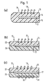
- Fig. 5
- eine hakenartige Oberflächenstruktur (a) und eine pilzförmig verbreiterte Oberflächenstruktur (b) einer erfindungsgemäßen elektrischen Leitung der dritten Variante.
- 10
- elektrische Leitung
- 12
- elektrisch leitendes Material
- 14
- elektrisch isolierendes Material
- 16
- Außenseite
- 18
- Haken
- 20
- elektrisch isolierendes Material
- 22
- elektrisch isolierendes Material
- 24
- Außenseite
- 26
- elektrisch isolierendes Material
- 28
- Außenseite
- 30
- Ösen
- 32
- elektrische Leitung
- 34
- elektrisch leitendes Material
- 36
- elektrisch isolierendes Material
- 38
- Oberfläche
- 40
- Haken
- 42
- erstes isolierendes Material
- 44
- zweites isolierendes Material
- 46
- Ösen
- 48
- Strangpressvorrichtung
- 50
- Isolationsummantelung
- 52
- Austrittsöffnung
- 54
- Andrückwalze
- 56
- Struktur
- 58
- Kühlvorrichtung
- 60
- Strukturierungswalze
- 62
- Mantelfläche
- 63
- Nadelöffnungen
- 64
- nadelartige Strukturen
- 66
- zweite Walze
- 68
- Spitzen
- 70
- unterer Abschnitt
Claims (28)
- Elektrische Leitung (10, 32) mit zumindest einem elektrisch leitenden Material (12, 34), das in wenigstens ein elektrisch isolierendes Material (14, 20, 22, 26, 36, 42, 44, 50) eingebettet ist, wobei die Oberfläche der elektrischen Leitung (10, 32) zumindest bereichsweise direkt und ohne Klebeverbindung in das elektrisch isolierende Material (14, 20, 22, 26, 36, 44, 50) integrierte klettverschlussartige Haken (18, 40) und/oder Ösen (30, 46) aufweist.
- Elektrische Leitung nach Anspruch 1,
dadurch gekennzeichnet, dass das elektrisch leitende Material (12) laminatartig zwischen zumindest zwei Schichten wenigstens eines elektrisch isolierenden Materials (14, 20, 22, 26) eingebettet ist, wobei zumindest eine der beiden Schichten durch eine wenigstens bereichsweise jeweils klettverschlussartige Haken (18) oder Ösen (30) aufweisende Struktur gebildet ist. - Elektrische Leitung nach Anspruch 2,
dadurch gekennzeichnet, dass die eine Schicht (22) eine Haken (18) aufweisende und die andere Schicht (26) eine Ösen (30) aufweisende Struktur ist. - Elektrische Leitung nach Anspruch 2,
dadurch gekennzeichnet, dass beide Schichten entweder Haken oder Ösen aufweisende Strukturen sind. - Elektrische Leitung nach einem der Ansprüche 2 bis 4,
dadurch gekennzeichnet, dass die Schichten jeweils unterschiedliche elektrisch isolierende Materialien (20, 22; 22, 26) aufweisen. - Elektrische Leitung nach einem der Ansprüche 2 bis 5,
dadurch gekennzeichnet, dass zumindest eine der Schichten (14, 20, 22, 26) eine Kunststofffolie aufweist. - Elektrische Leitung nach einem der Ansprüche 2 bis 6,
dadurch gekennzeichnet, dass zumindest eine der Schichten (14, 20, 22, 26) ein Gewebematerial aufweist. - Elektrische Leitung nach einem der vorherigen Ansprüche,
dadurch gekennzeichnet, dass die elektrische Leitung (10) ein flexibles Flachbandkabel ist. - Elektrische Leitung nach einem der vorherigen Ansprüche,
dadurch gekennzeichnet, dass die elektrische Leitung (10) eine flexible gedruckte Schaltung ist. - Elektrische Leitung nach Anspruch 1,
dadurch gekennzeichnet, dass das elektrisch isolierende Material (36, 44, 50) zumindest bereichsweise mit einer klettverschlussartige Haken (40) oder Ösen (46) aufweisenden Struktur (56) versehen ist, die mit dem elektrisch isolierenden Material (36, 44, 50) eine Schmelzverbindung bildet. - Elektrische Leitung nach Anspruch 1,
dadurch gekennzeichnet, dass die klettverschlussartigen Haken (40) aus dem elektrisch isolierenden Material (36, 44, 50) selbst gebildet sind. - Verfahren zum Versehen einer Oberfläche einer elektrischen Leitung (10, 32) mit klettverschlussartigen Haken (18, 40) oder Ösen (30, 46), bei dem
wenigstens ein elektrisch leitfähiges Material (12, 34) in zumindest ein elektrisch isolierendes Material (36, 42, 44, 50) eingebettet wird, wobei
das elektrisch isolierende Material (36, 42, 44) zumindest bereichsweise durch wenigstens eine klettverschlussartige Haken (40) oder Ösen (46) aufweisende Struktur (56) gebildet wird. - Verfahren nach Anspruch 12,
dadurch gekennzeichnet, dass das elektrisch leitfähige Material (12) durch einen Laminiervorgang zwischen zumindest zwei Schichten wenigstens eines elektrisch isolierenden Materials (14, 20, 22, 26) eingebettet wird, wobei mindestens eine der Schichten durch eine wenigstens bereichsweise klettverschlussartige Haken (18) oder Ösen (30) aufweisende Struktur gebildet wird. - Verfahren nach Anspruch 12,
dadurch gekennzeichnet, dass eine auf ihrer einen Seite klettverschlussartige Haken (40) oder Ösen (46) aufweisende Struktur (56) mit ihrer anderen Seite zumindest abschnittsweise auf die Oberfläche des elektrisch isolierenden Materials (36, 44, 50) aufgebracht wird, wobei das elektrisch isolierende Material (36, 44, 50) bei Aufbringen der Struktur eine derart hohe Temperatur aufweist, dass es mit der Struktur (56) eine Schmelzverbindung eingeht. - Verfahren zum Versehen einer Oberfläche einer elektrischen Leitung (32) mit klettverschlussartigen Haken (40), bei dem
wenigstens ein elektrisch leitfähiges Material (34) in zumindest ein elektrisch isolierendes Material (36, 44, 50) eingebettet wird und
zumindest bereichsweise direkt in dem elektrisch isolierenden Material (36, 44, 50) selbst klettverschlussartige Haken (40) gebildet werden. - Verfahren nach Anspruch 15,
dadurch gekennzeichnet, dass in dem elektrisch isolierenden Material (36, 44, 50) selbst mittels eines ersten Strukturierungsmittels (60) nadelartige Strukturen (64) erzeugt werden. - Verfahren nach Anspruch 16,
dadurch gekennzeichnet, dass die nadelartigen Strukturen (64) durch einen Prägevorgang erzeugt werden. - Verfahren nach Anspruch 16 oder 17,
dadurch gekennzeichnet, dass die nadelartigen Strukturen (64) durch eine erste Walze (60) erzeugt werden, die mit einem Oberflächenbereich des elektrisch isolierenden Materials (36, 44, 50) in Berührung gebracht wird. - Verfahren nach einem der Ansprüche 16 bis 18,
dadurch gekennzeichnet, dass die Bildung der nadelartigen Strukturen (64) bei einer Temperatur des elektrisch isolierenden Materials (36, 44, 50) erfolgt, bei der das elektrisch isolierende Material (36, 44, 50) leicht verformbar ist. - Verfahren nach einem der Ansprüche 12 bis 19,
dadurch gekennzeichnet, dass die Spitzen (68) der nadelartigen Strukturen (64) mittels eines zweiten Strukturierungsmittels (66) zu Haken (40) umgeformt werden. - Verfahren nach Anspruch 20,
dadurch gekennzeichnet, dass die Spitzen (68) der nadelartigen Strukturen (64) durch eine zur Längserstreckung der elektrischen Leitung (32) parallelen Relativbewegung der elektrischen Leitung (32) bezüglich einer zweiten Walze (66) umgebogen oder verbreitert werden. - Verfahren nach Anspruch 20 oder 21,
dadurch gekennzeichnet, dass das Umformen der Spitzen (68) der nadelartigen Strukturen (64) nach einer Abkühlung des elektrisch isolierenden Materials (36, 44, 50) auf eine Temperatur erfolgt, bei der die nadelartigen Strukturen (64) erstarren, wobei das zweite Strukturierungsmittel (66) eine zur Verformung des elektrisch isolierenden Materials (36, 44, 50) benötigte Temperatur aufweist. - Verfahren nach einem der Ansprüche 14 bis 22,
dadurch gekennzeichnet, dass zumindest ein elektrisch leitender Materialstrang (34) in einer Strangpressvorrichtung (48) mit wenigstens einer Kunststoffummantelung (50) versehen wird. - Verfahren nach einem der Ansprüche 14 bis 23,
dadurch gekennzeichnet, dass das Versehen der elektrischen Leitung (32) mit den klettverschlussartigen Haken (40) oder Ösen (46) unmittelbar nach dem Austreten der elektrischen Leitung (32) aus einer Strangpressvorrichtung (48) erfolgt. - Anordnung zum Aufbringen einer klettverschlussartigen Haken (40) oder Ösen (46) aufweisenden Struktur (56) in zumindest einem Oberflächenbereich einer elektrischen Leitung (32), mit einer Strangpressvorrichtung (48) zum Versehen zumindest eines elektrisch leitenden Materialstrangs (34) mit wenigstens einer Kunststoffummantelung (50) und einer im Ausgangsbereich der Strangpressvorrichtung (48) angeordneten Andrückwalze (54) zum Andrücken einer an ihrer der elektrischen Leitung (32) abgewandten Seite klettverschlussartige Haken (40) oder Ösen (46) aufweisenden Struktur (56) an die elektrische Leitung (32), wobei die elektrische Leitung (32) mit der Struktur (56) eine Schmelzverbindung eingeht.
- Anordnung zum Versehen zumindest eines Oberflächenbereiches einer elektrischen Leitung (32) mit klettverschlussartigen Haken (40), mit einer Strangpressvorrichtung (48) zum Versehen zumindest eines elektrisch leitenden Materialstrangs (34) mit wenigstens einer Kunststoffummantelung (50), einem im Ausgangsbereich der Strangpressvorrichtung (48) angeordneten ersten und zweiten Strukturierungsmittel (60, 66), einer zwischen den Strukturierungsmitteln (60, 66) angeordneten Kühlvorrichtung (58) zum Abkühlen der elektrischen Leitung (32) und einer Vorschubeinrichtung, um die elektrische Leitung (32) an den Strukturierungsmitteln (60, 66) vorbei und durch die Kühlvorrichtung (58) hindurch zu führen.
- Anordnung nach Anspruch 26,
dadurch gekennzeichnet, dass das erste Strukturierungsmittel eine, insbesondere heizbare, Walze (60) ist, deren Mantelfläche (62) insbesondere mit Nadelöffnungen (63) versehen ist, um in dem Oberflächenbereich nadelartige Strukturen (64) zu erzeugen. - Anordnung nach Anspruch 27,
dadurch gekennzeichnet, dass das zweite Strukturierungsmittel eine heizbare Walze (66) ist, deren Mantelfläche insbesondere glatt ausgebildet ist, um die nadelartigen Strukturen (64) zu Haken (40)
Applications Claiming Priority (2)
| Application Number | Priority Date | Filing Date | Title |
|---|---|---|---|
| DE10105089A DE10105089A1 (de) | 2001-02-05 | 2001-02-05 | Elektrischer Leiter |
| DE10105089 | 2001-02-05 |
Publications (3)
| Publication Number | Publication Date |
|---|---|
| EP1229556A2 true EP1229556A2 (de) | 2002-08-07 |
| EP1229556A3 EP1229556A3 (de) | 2003-08-20 |
| EP1229556B1 EP1229556B1 (de) | 2009-05-06 |
Family
ID=7672865
Family Applications (1)
| Application Number | Title | Priority Date | Filing Date |
|---|---|---|---|
| EP02001819A Expired - Lifetime EP1229556B1 (de) | 2001-02-05 | 2002-01-25 | Elektrische Leitung |
Country Status (3)
| Country | Link |
|---|---|
| US (1) | US6621007B2 (de) |
| EP (1) | EP1229556B1 (de) |
| DE (2) | DE10105089A1 (de) |
Cited By (2)
| Publication number | Priority date | Publication date | Assignee | Title |
|---|---|---|---|---|
| WO2004030994A1 (de) * | 2002-09-30 | 2004-04-15 | Johnson Controls Gmbh | Vorverkabeltes ausstattungsteil, leitungsstrang und verfahren zu seiner herstellung |
| CN105355295A (zh) * | 2015-11-18 | 2016-02-24 | 乐山市同源科技有限公司 | 免安装导线 |
Families Citing this family (7)
| Publication number | Priority date | Publication date | Assignee | Title |
|---|---|---|---|---|
| DE60139516D1 (de) * | 2000-10-25 | 2009-09-17 | Velcro Ind | Verfahren zur kontinuierlichen Herstellung eines elektrischen Kabels |
| DE20211568U1 (de) | 2002-07-15 | 2002-11-07 | LEONI Bordnetz-Systeme GmbH & Co KG, 90402 Nürnberg | Haltevorrichtung zum Befestigen eines strangförmigen Körpers auf einem flächigen Bauteil |
| EP1759929A4 (de) * | 2004-05-31 | 2010-04-21 | Furukawa Electric Co Ltd | Energieversorgungssystem für fahrzeug |
| JP4776942B2 (ja) * | 2005-02-21 | 2011-09-21 | 矢崎総業株式会社 | ワイヤーハーネスおよびワイヤーハーネスの積層方法 |
| US8061886B1 (en) | 2008-04-30 | 2011-11-22 | Velcro Industries B.V. | Securing electrical devices |
| CN101320603A (zh) * | 2008-06-25 | 2008-12-10 | 上海序参量科技发展有限公司 | 自粘型导线 |
| DE102009020944A1 (de) * | 2009-05-13 | 2010-11-18 | Gottlieb Binder Gmbh & Co. Kg | Haftverschlusselement |
Family Cites Families (15)
| Publication number | Priority date | Publication date | Assignee | Title |
|---|---|---|---|---|
| US4602191A (en) * | 1984-07-23 | 1986-07-22 | Xavier Davila | Jacket with programmable lights |
| DE3911017A1 (de) * | 1989-04-05 | 1990-10-11 | Ensslin Gmbh & Co | Labor- oder werkstattmoebel |
| DE3918314A1 (de) * | 1989-06-05 | 1990-12-06 | Rxs Schrumpftech Garnituren | Verschluss- und verbindungssystem fuer waermeschrumpffaehige formteile |
| GB2256977A (en) * | 1990-10-19 | 1992-12-23 | Eric Pilkington | Connecting wires to electric plug using hook-and-loop strip |
| DE4138714A1 (de) * | 1991-11-21 | 1993-05-27 | Siemens Ag | Leitungssatz fuer das bordnetz eines kraftfahrzeuges |
| JP2570336Y2 (ja) * | 1991-11-28 | 1998-05-06 | 矢崎総業株式会社 | テープ電線 |
| JP2942458B2 (ja) * | 1993-04-16 | 1999-08-30 | 住友電気工業株式会社 | フラットケーブル用導体の製造方法および製造設備 |
| DE4428708C1 (de) * | 1994-08-14 | 1995-07-06 | Peter Schoelles | Kabelhalter |
| DE19623575A1 (de) * | 1996-06-13 | 1997-12-18 | Volkswagen Ag | Vorverkabeltes Auskleidungsteil für die Innenauskleidung eines Fahrzeuges |
| DE19650227C1 (de) * | 1996-12-04 | 1997-11-27 | Webasto Karosseriesysteme | Fahrzeugdach mit Kabelverbindung |
| DE19726887A1 (de) * | 1997-06-25 | 1999-01-07 | Frank Janczyk | Profilleiste |
| DE19832486A1 (de) * | 1998-07-20 | 2000-01-27 | Louda Syst Gmbh | Maschinenlesbare Ausweiskarte mit ausechselbaren Funktionselementen |
| DE29900924U1 (de) * | 1999-01-20 | 2000-06-29 | Coroplast Fritz Müller GmbH & Co. KG, 42279 Wuppertal | Velours-Klebeband |
| JP2001291433A (ja) * | 2000-04-05 | 2001-10-19 | Auto Network Gijutsu Kenkyusho:Kk | フラットケーブル、フラットケーブルの製造方法およびフラットケーブルの配索方法 |
| US6397438B1 (en) * | 2000-09-26 | 2002-06-04 | Dewan Thomas E. | Embedded hook and loop fastener |
-
2001
- 2001-02-05 DE DE10105089A patent/DE10105089A1/de not_active Withdrawn
-
2002
- 2002-01-15 US US10/047,429 patent/US6621007B2/en not_active Expired - Lifetime
- 2002-01-25 DE DE50213513T patent/DE50213513D1/de not_active Expired - Lifetime
- 2002-01-25 EP EP02001819A patent/EP1229556B1/de not_active Expired - Lifetime
Cited By (2)
| Publication number | Priority date | Publication date | Assignee | Title |
|---|---|---|---|---|
| WO2004030994A1 (de) * | 2002-09-30 | 2004-04-15 | Johnson Controls Gmbh | Vorverkabeltes ausstattungsteil, leitungsstrang und verfahren zu seiner herstellung |
| CN105355295A (zh) * | 2015-11-18 | 2016-02-24 | 乐山市同源科技有限公司 | 免安装导线 |
Also Published As
| Publication number | Publication date |
|---|---|
| EP1229556A3 (de) | 2003-08-20 |
| DE50213513D1 (de) | 2009-06-18 |
| EP1229556B1 (de) | 2009-05-06 |
| US6621007B2 (en) | 2003-09-16 |
| US20020104677A1 (en) | 2002-08-08 |
| DE10105089A1 (de) | 2002-08-08 |
Similar Documents
| Publication | Publication Date | Title |
|---|---|---|
| DE60125834T2 (de) | Befestigung elektrischer leiter | |
| EP1835786B1 (de) | Flächenheizelement und Verfahren zur Herstellung eines Flächenheizelementes | |
| DE112019002733B4 (de) | Verkabelungselement | |
| DE68928244T2 (de) | Verfahren zur Herstellung eines flachen Kabelbaumes | |
| DE112018000959T5 (de) | Kabelbaum | |
| DE112018008281B4 (de) | Kabelbaum | |
| DE102020127121A1 (de) | Heizelement für ein Oberflächenbauteil in einem Kraftfahrzeug | |
| DE112018007359B4 (de) | Kabelbaum mit Befestigungselement | |
| DE19819088B4 (de) | Flexible Leiterplatte | |
| EP1229556B1 (de) | Elektrische Leitung | |
| DE102016114945B4 (de) | Elektrische Flachleiteranordnung und Herstellungsverfahren für eine solche | |
| EP1420997B1 (de) | Kraftfahrzeug-baugruppe | |
| DE4243336C2 (de) | Flachkabel | |
| DE2758472A1 (de) | Verfahren zur herstellung eines flachen kabelbaumes und vorrichtung zur durchfuehrung des verfahrens | |
| DE20211568U1 (de) | Haltevorrichtung zum Befestigen eines strangförmigen Körpers auf einem flächigen Bauteil | |
| DE112018005396B4 (de) | Kabelstrang | |
| DE102018118778A1 (de) | Sicherheitsgurt mit elektrischer Einheit | |
| EP1336182A1 (de) | Verfahren zum herstellen von flachbandkabeln | |
| DE10103367C2 (de) | Verfahren zum Herstellen von Flachbandkabeln | |
| DE112022001194T5 (de) | Verkabelungsbauteil | |
| DE20204011U1 (de) | Elektrische Verbindungsanordnung mit einer Folienleiterplatte oder einem Folienleiterkabel sowie elektrisches Brückenelement und Verarbeitungseinheit für diese Anordnung | |
| DE102016114944A1 (de) | Elektrische Flachleiteranordnung und Herstellungsverfahren für eine solche | |
| DE102012002945B4 (de) | Multifunktionelle Mehrlagenleiterplatten mit einer elektrisch leitfähigen Hochstrom-Leitstruktur und Verfahren zur Herstellung | |
| EP1349182B1 (de) | Verfahren zur Herstellung einer Flachleiter-Bandleitung | |
| DE10056442B4 (de) | Leitungskanal und Verfahren zu seiner Herstellung |
Legal Events
| Date | Code | Title | Description |
|---|---|---|---|
| PUAI | Public reference made under article 153(3) epc to a published international application that has entered the european phase |
Free format text: ORIGINAL CODE: 0009012 |
|
| AK | Designated contracting states |
Kind code of ref document: A2 Designated state(s): AT BE CH CY DE DK ES FI FR GB GR IE IT LI LU MC NL PT SE TR |
|
| AX | Request for extension of the european patent |
Free format text: AL;LT;LV;MK;RO;SI |
|
| PUAL | Search report despatched |
Free format text: ORIGINAL CODE: 0009013 |
|
| AK | Designated contracting states |
Designated state(s): AT BE CH CY DE DK ES FI FR GB GR IE IT LI LU MC NL PT SE TR |
|
| AX | Request for extension of the european patent |
Extension state: AL LT LV MK RO SI |
|
| RIC1 | Information provided on ipc code assigned before grant |
Ipc: 7H 01B 7/40 A Ipc: 7B 60R 16/02 B |
|
| 17P | Request for examination filed |
Effective date: 20030926 |
|
| AKX | Designation fees paid |
Designated state(s): DE FR IT |
|
| 17Q | First examination report despatched |
Effective date: 20080728 |
|
| GRAP | Despatch of communication of intention to grant a patent |
Free format text: ORIGINAL CODE: EPIDOSNIGR1 |
|
| GRAS | Grant fee paid |
Free format text: ORIGINAL CODE: EPIDOSNIGR3 |
|
| GRAA | (expected) grant |
Free format text: ORIGINAL CODE: 0009210 |
|
| AK | Designated contracting states |
Kind code of ref document: B1 Designated state(s): DE FR IT |
|
| REF | Corresponds to: |
Ref document number: 50213513 Country of ref document: DE Date of ref document: 20090618 Kind code of ref document: P |
|
| PLBE | No opposition filed within time limit |
Free format text: ORIGINAL CODE: 0009261 |
|
| STAA | Information on the status of an ep patent application or granted ep patent |
Free format text: STATUS: NO OPPOSITION FILED WITHIN TIME LIMIT |
|
| 26N | No opposition filed |
Effective date: 20100209 |
|
| PGFP | Annual fee paid to national office [announced via postgrant information from national office to epo] |
Ref country code: FR Payment date: 20120202 Year of fee payment: 11 |
|
| PGFP | Annual fee paid to national office [announced via postgrant information from national office to epo] |
Ref country code: DE Payment date: 20120118 Year of fee payment: 11 |
|
| PGFP | Annual fee paid to national office [announced via postgrant information from national office to epo] |
Ref country code: IT Payment date: 20120116 Year of fee payment: 11 |
|
| REG | Reference to a national code |
Ref country code: FR Ref legal event code: ST Effective date: 20130930 |
|
| PG25 | Lapsed in a contracting state [announced via postgrant information from national office to epo] |
Ref country code: DE Free format text: LAPSE BECAUSE OF NON-PAYMENT OF DUE FEES Effective date: 20130801 |
|
| REG | Reference to a national code |
Ref country code: DE Ref legal event code: R119 Ref document number: 50213513 Country of ref document: DE Effective date: 20130801 |
|
| PG25 | Lapsed in a contracting state [announced via postgrant information from national office to epo] |
Ref country code: FR Free format text: LAPSE BECAUSE OF NON-PAYMENT OF DUE FEES Effective date: 20130131 |
|
| PG25 | Lapsed in a contracting state [announced via postgrant information from national office to epo] |
Ref country code: IT Free format text: LAPSE BECAUSE OF NON-PAYMENT OF DUE FEES Effective date: 20130125 |