EP1229191B1 - Betätigungsvorrichtung für Entriegelungseinrichtungen von Fahrzeugen, vorzugsweise von Kraftfahrzeugen - Google Patents
Betätigungsvorrichtung für Entriegelungseinrichtungen von Fahrzeugen, vorzugsweise von Kraftfahrzeugen Download PDFInfo
- Publication number
- EP1229191B1 EP1229191B1 EP02001769A EP02001769A EP1229191B1 EP 1229191 B1 EP1229191 B1 EP 1229191B1 EP 02001769 A EP02001769 A EP 02001769A EP 02001769 A EP02001769 A EP 02001769A EP 1229191 B1 EP1229191 B1 EP 1229191B1
- Authority
- EP
- European Patent Office
- Prior art keywords
- antenna
- advantageously
- rectifier
- control
- oscillator
- Prior art date
- Legal status (The legal status is an assumption and is not a legal conclusion. Google has not performed a legal analysis and makes no representation as to the accuracy of the status listed.)
- Expired - Lifetime
Links
Images

Classifications
-
- E—FIXED CONSTRUCTIONS
- E05—LOCKS; KEYS; WINDOW OR DOOR FITTINGS; SAFES
- E05B—LOCKS; ACCESSORIES THEREFOR; HANDCUFFS
- E05B81/00—Power-actuated vehicle locks
- E05B81/24—Power-actuated vehicle locks characterised by constructional features of the actuator or the power transmission
- E05B81/25—Actuators mounted separately from the lock and controlling the lock functions through mechanical connections
-
- G—PHYSICS
- G07—CHECKING-DEVICES
- G07C—TIME OR ATTENDANCE REGISTERS; REGISTERING OR INDICATING THE WORKING OF MACHINES; GENERATING RANDOM NUMBERS; VOTING OR LOTTERY APPARATUS; ARRANGEMENTS, SYSTEMS OR APPARATUS FOR CHECKING NOT PROVIDED FOR ELSEWHERE
- G07C9/00—Individual registration on entry or exit
- G07C9/00174—Electronically operated locks; Circuits therefor; Nonmechanical keys therefor, e.g. passive or active electrical keys or other data carriers without mechanical keys
- G07C9/00182—Electronically operated locks; Circuits therefor; Nonmechanical keys therefor, e.g. passive or active electrical keys or other data carriers without mechanical keys operated with unidirectional data transmission between data carrier and locks
-
- E—FIXED CONSTRUCTIONS
- E05—LOCKS; KEYS; WINDOW OR DOOR FITTINGS; SAFES
- E05B—LOCKS; ACCESSORIES THEREFOR; HANDCUFFS
- E05B47/00—Operating or controlling locks or other fastening devices by electric or magnetic means
-
- E—FIXED CONSTRUCTIONS
- E05—LOCKS; KEYS; WINDOW OR DOOR FITTINGS; SAFES
- E05B—LOCKS; ACCESSORIES THEREFOR; HANDCUFFS
- E05B83/00—Vehicle locks specially adapted for particular types of wing or vehicle
- E05B83/16—Locks for luggage compartments, car boot lids or car bonnets
-
- G—PHYSICS
- G07—CHECKING-DEVICES
- G07C—TIME OR ATTENDANCE REGISTERS; REGISTERING OR INDICATING THE WORKING OF MACHINES; GENERATING RANDOM NUMBERS; VOTING OR LOTTERY APPARATUS; ARRANGEMENTS, SYSTEMS OR APPARATUS FOR CHECKING NOT PROVIDED FOR ELSEWHERE
- G07C9/00—Individual registration on entry or exit
- G07C9/00174—Electronically operated locks; Circuits therefor; Nonmechanical keys therefor, e.g. passive or active electrical keys or other data carriers without mechanical keys
- G07C9/00182—Electronically operated locks; Circuits therefor; Nonmechanical keys therefor, e.g. passive or active electrical keys or other data carriers without mechanical keys operated with unidirectional data transmission between data carrier and locks
- G07C2009/00206—Electronically operated locks; Circuits therefor; Nonmechanical keys therefor, e.g. passive or active electrical keys or other data carriers without mechanical keys operated with unidirectional data transmission between data carrier and locks the keyless data carrier being hand operated
- G07C2009/00214—Electronically operated locks; Circuits therefor; Nonmechanical keys therefor, e.g. passive or active electrical keys or other data carriers without mechanical keys operated with unidirectional data transmission between data carrier and locks the keyless data carrier being hand operated by one push button
-
- G—PHYSICS
- G07—CHECKING-DEVICES
- G07C—TIME OR ATTENDANCE REGISTERS; REGISTERING OR INDICATING THE WORKING OF MACHINES; GENERATING RANDOM NUMBERS; VOTING OR LOTTERY APPARATUS; ARRANGEMENTS, SYSTEMS OR APPARATUS FOR CHECKING NOT PROVIDED FOR ELSEWHERE
- G07C9/00—Individual registration on entry or exit
- G07C9/00174—Electronically operated locks; Circuits therefor; Nonmechanical keys therefor, e.g. passive or active electrical keys or other data carriers without mechanical keys
- G07C2009/00579—Power supply for the keyless data carrier
- G07C2009/00603—Power supply for the keyless data carrier by power transmission from lock
-
- Y—GENERAL TAGGING OF NEW TECHNOLOGICAL DEVELOPMENTS; GENERAL TAGGING OF CROSS-SECTIONAL TECHNOLOGIES SPANNING OVER SEVERAL SECTIONS OF THE IPC; TECHNICAL SUBJECTS COVERED BY FORMER USPC CROSS-REFERENCE ART COLLECTIONS [XRACs] AND DIGESTS
- Y10—TECHNICAL SUBJECTS COVERED BY FORMER USPC
- Y10T—TECHNICAL SUBJECTS COVERED BY FORMER US CLASSIFICATION
- Y10T74/00—Machine element or mechanism
- Y10T74/11—Tripping mechanism
Definitions
- the invention relates to an actuating device for unlocking devices of vehicles, preferably of motor vehicles, according to the preamble of claim 1.
- a rear window in the tailgate is arranged pivotably.
- the rear window is in the Locked position secured by an unlocking device.
- an actuating element is provided on the rear window, with which a control relay is actuated by pressing. It ensures that the rear window is released and opened can be.
- the connection between the actuator and the control takes place via lines. Their laying is complex and difficult. Plug connections are required here can loosen or even loosen during operation. Then you can Do not unlock the rear window.
- actuating device (DE-A-199 27 179) is a cover of the luggage compartment with the actuating element Motor vehicle unlocked and opened.
- the actuator emits radiation that emits radiation from a remote control Locking system of the motor vehicle corresponds so that the Lid can be unlocked or opened.
- the invention has for its object the generic actuator trained so that they are easy to assemble can and a failure or malfunction of the release even under extreme conditions is reliably avoided.
- the trigger signal transmitted wirelessly from the actuator to the controller. Because of the wireless unlocking, lines are cables and the like not necessary. This makes it a very simple one Assembly of the actuator guaranteed. It is above Furthermore, not susceptible to faults and in particular free of wear. An outage or a disturbance of the unlocking is therefore also under extreme Conditions excluded.
- the actuator is part of a passive receiver. It advantageously has a preferably as a planar antenna trained passive antenna.
- the actuator and the controller are only a short distance apart, so that even low powers are sufficient to transmit the signal, to unlock it. So the distance between the actuator and the control, for example, only 1 to 2 cm.
- the actuator will be unlocked Component provided, while the control on the body side Vehicle is arranged.
- the actuator is used in motor vehicles and serves, for example, a rear window 37 (FIGS. 3 and 4) Unlock motor vehicle.
- the actuator can also for opening a trunk lid, a bonnet or a glove compartment of a motor vehicle are used.
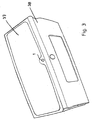
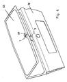
- in the illustrated embodiment serves the actuator for unlocking a rear window 37 of a motor vehicle, which in a pivotable tailgate 38 is provided. After unlocking the rear window 37 can be separated from the tailgate 38 be swung up.
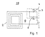
- a receiver 39 is located on the rear window 37 of the motor vehicle a button 1 is provided, which is connected to a planar antenna 2 is. It is adjusted to a predetermined value via a matching element 3 Tuned resonance frequency. In the simplest and preferred Fall is the adjustment element 3 by two parallel Capacitors 4, 5 formed. You can be adjustable.
- the button 1 is pressed and thus the resonant circuit 6 closed.
- the resonance frequency 13.560 MHz.
- the resonance frequency be chosen differently.
- the resonant circuit 6 with the planar antenna 2 and the button 1 forms a passive antenna. It does not have to be powered.
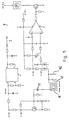
- the battery voltage which in the example is 12 volts, is determined by a voltage regulator 15 stabilized, in the embodiment to 7 volts.
- the input and the output of the controller 15 is in each case a resistor 35 and 36 assigned. That at the output of the controller 15 applied signal is fed to the plus input of the comparator 13, which is the controller signal with the rectified output signal of the oscillator 9 compares and delivers the control signal.
- the oscillator 9 has a transistor 16 which is connected via the quartz 11 in Resonance frequency preferably 13.560 MHz (ISM band) to the transmitting antenna 8 is brought. It is advantageously a planar antenna. you connected in series are two series resistors 17, 18, a voltage divider to the base or to the working point of the Form transistor 16. Parallel to resistor 17 or in series with Resistor 18 has two capacitors 19, 20, which are used for the feedback are responsible for generating the vibration amplitude. A resistor 21 determines the emitter current to the transistor 16th
- the oscillator 9 is provided with a low-pass filter 22 from the outside to screen out incoming interference.
- the low pass 22 consists of a resistor 23, a capacitor 24 and a resistor 25 are subordinate.
- Resistor 25 is in the collector circuit of transistor 16 is connected and is in series with resistor 18 of the voltage divider.
- the rectifier 12 is advantageously temperature compensated so that the offset voltage of the comparator input not changed.
- the rectifier 12 is included two diodes 26, 27 combined to form a unit, which are thermally integrated on a chip.
- the decoupling point 10 on the oscillator 9 is formed by a capacitor that is set that the voltage is still so high that it Threshold voltage of the rectifier 12 exceeds sufficiently far, in order to enable a reliable evaluation in the comparator 13.
- the decoupling point 10 of the oscillator 9 is a low-pass filter 28, 29 downstream to suppress RF interference from the outside could lead to an unwanted actuation of the control.
- the inductor 28 and the capacitor 29, which are the diodes, have a low pass 26, 27 are connected upstream.
- both the plus and A low-pass filter is connected upstream of the negative input of the comparator 13.
- the low pass assigned to the plus input consists of a Resistor 30 and a downstream capacitor 31.
- the low-pass filter assigned to the minus input of the comparator 13 the resistor 32 and the downstream capacitor 33. Die have two resistors 30, 32 and the two capacitors 31, 33 same characteristics.
- a low-resistance load 34 are operated.
- the resonance circuit 3 By pressing the button 1 of the passive element, the resonance circuit 3 closed, whereby 7 energy is removed from the transmitter becomes. It leads to the triggering of a control signal, which causes the unlocking of the rear window 37 is reached.
- the transfer between the passive element and the transmitter 7 are used the resonance frequency wired or wireless.
- the passive Secondary circuit 6, which is tuned to the transmission frequency or via the button 1 is out of tune with the transmission frequency, deprives the In the resonance case, oscillator 9 has sufficient energy so that the waste the RF voltage across the RF rectifier 12 to the following Comparator circuit is detected. It provides a corresponding one at output 14 Logic signal to control a power FET switch 40, with which the unlocking of the rear window 37 is reached becomes.
- the transmitter 7 Due to the wireless unlocking of the rear window 37 without use of lines, cables and the like results in a very simple assembly of the actuator. It is not prone to failure and is particularly wear-free.
- the transmitter 7 only needs a minimum current, which is, for example, only about 3 mA. As a result, the transmitter 7 can also be in the standby position for a long time be without the vehicle battery which transmitter is connected, too much energy is being drawn.
- the transmitter 7 with the central locking of the motor vehicle to couple. If the vehicle is centrally locked, it is too the transmitter 7 is switched off so that it does not require any current. Becomes the central locking is opened, the transmitter 7 is also switched on, so that it is ready for use. If the transmitter 7 via the central locking switched off, there is no possibility for unauthorized persons manipulate the transmitter 7 from the outside and the rear window 37 to open without authorization.
- Fig. 5 shows a transmitter 7, in which the quartz 11 resonates with part of the antenna 8 and capacitors connected to it 41, 42 is. As a result, the load on the quartz 11 becomes low held. By tapping the antenna 8 (coil) on upper coil tap a higher useful amplitude. This allows the Sensitivity increased with low quartz load become.
- the senor is essentially the same as in the previous embodiment. It works the same as the previous one Embodiment.
Description
- Fig. 1
- einen Empfänger einer erfindungsgemäßen Betätigungsvorrichtung,
- Fig. 2
- einen Schaltplan eines Senders der erfindungsgemäßen Betätigungsvorrichtung,
- Fig. 3
- eine Heckklappe mit einem in Schließstellung befindlichen Heckfensters eines Kraftfahrzeuges, das mit der erfindungsgemäßen Betätigungsvorrichtung versehen ist,
- Fig. 4
- das Heckfenster gemäß Fig. 3 in geöffneter Stellung,
- Fig. 5
- einen Schaltplan eines Senders einer zweiten Ausführungsform einer erfindungsgemäßen Betätigungsvorrichtung.
Claims (12)
- Betätigungsvorrichtung für Entriegelungseinrichtungen von Fahrzeugen, vorzugsweise von Kraftfahrzeugen, mit wenigstens einer Steuerung (7) und einem Betätigungselement (1), das bei Betätigung ein Signal drahtlos an die Steuerung (7) zur Entriegelung abgibt,
dadurch gekennzeichnet, daß das Betätigungselement (1) Teil eines passiven Empfängers ist, der vorteilhaft eine vorzugsweise als Planarantenne ausgebildete Passivantenne (2) aufweist. - Vorrichtung nach Anspruch 1,
dadurch gekennzeichnet, daß das Betätigungselement (1) ein Taster ist. - Vorrichtung nach Anspruch 1 oder 2,
dadurch gekennzeichnet, daß die Passivantenne (2) in einem Resonanzkreis liegt, der vorzugsweise durch Betätigen des Betätigungselementes (1) geschlossen wird. - Vorrichtung nach Anspruch 3,
dadurch gekennzeichnet, daß zur Abstimmung der Passivantenne (2) auf die Resonanzfrequenz ein Abstimmelement (3) vorgesehen ist, das vorteilhaft zwei parallel zueinander liegende Kondensatoren (4, 5) aufweist. - Vorrichtung nach einem der Ansprüche 1 bis 4,
dadurch gekennzeichnet, daß die Steuerung (7) wenigstens eine Antenne (8), vorzugsweise eine Planarantenne, aufweist, der vorteilhaft durch Betätigen des Betätigungselementes (1) Energie entzogen wird. - Vorrichtung nach Anspruch 5,
dadurch gekennzeichnet, daß die Antenne (8) Teil eines Oszillators (9) ist, der vorteilhaft ein Schaltelement (16), vorzugsweise einen Transistor, aufweist. - Vorrichtung nach Anspruch 6,
dadurch gekennzeichnet, daß das Schaltelement (16) über einen Quarz (11) in Resonanz zur Antenne (8) gebracht wird. - Vorrichtung nach Anspruch 6 oder 7,
dadurch gekennzeichnet, daß dem Oszillator (9) ein Gleichrichter (12) nachgeschaltet ist, dessen Ausgangssignal vorteilhaft einem Komparator (13) zugeführt wird. - Vorrichtung nach Anspruch 8,
dadurch gekennzeichnet, daß der Gleichrichter (12) ein Temperaturkompensationsglied (26, 27) aufweist. - Vorrichtung nach einem der Ansprüche 5 bis 9,
dadurch gekennzeichnet, daß die Ausgangsspannung des Oszillators (9) herabgesetzt und dem Komparator (13) zugeführt wird, der vorteilhaft das Ausgangssignal des Gleichrichters (12) mit einem Reglersignal vergleicht. - Vorrichtung nach einem der Ansprüche 8 bis 10,
dadurch gekennzeichnet, daß das Ausgangssignal des Komparators (13) zur Entriegelung herangezogen wird. - Vorrichtung nach einem der Ansprüche 6 bis 11,
dadurch gekennzeichnet, daß eine Auskoppelungsstelle des Oszillators (9) durch einen Kondensator (10) gebildet ist, der vorteilhaft die Spannung oberhalb der Schwellspannung des Gleichrichters (12) hält.
Applications Claiming Priority (2)
| Application Number | Priority Date | Filing Date | Title |
|---|---|---|---|
| DE10104377 | 2001-02-01 | ||
| DE10104377A DE10104377A1 (de) | 2001-02-01 | 2001-02-01 | Betätigungsvorrichtung für Entriegelungseinrichtungen von Fahrzeugen, vorzugsweise von Kraftfahrzeugen |
Publications (3)
| Publication Number | Publication Date |
|---|---|
| EP1229191A2 EP1229191A2 (de) | 2002-08-07 |
| EP1229191A3 EP1229191A3 (de) | 2002-08-14 |
| EP1229191B1 true EP1229191B1 (de) | 2004-11-17 |
Family
ID=7672389
Family Applications (1)
| Application Number | Title | Priority Date | Filing Date |
|---|---|---|---|
| EP02001769A Expired - Lifetime EP1229191B1 (de) | 2001-02-01 | 2002-01-25 | Betätigungsvorrichtung für Entriegelungseinrichtungen von Fahrzeugen, vorzugsweise von Kraftfahrzeugen |
Country Status (3)
| Country | Link |
|---|---|
| US (1) | US6794767B2 (de) |
| EP (1) | EP1229191B1 (de) |
| DE (2) | DE10104377A1 (de) |
Families Citing this family (6)
| Publication number | Priority date | Publication date | Assignee | Title |
|---|---|---|---|---|
| US7121605B2 (en) * | 2004-03-17 | 2006-10-17 | Lear Corporation | Glove box with sensor |
| DE102004059214B4 (de) | 2004-12-09 | 2018-07-26 | Volkswagen Ag | Anordnung für ein Kraftfahrzeug mit einer Aufstellscheibe, einem Schloss und Mitteln zum elektromotorischen Entriegeln des Schlosses |
| FR2909340B1 (fr) * | 2006-11-30 | 2009-01-02 | Peugeot Citroen Automobiles Sa | Lunette arriere ouvrante pour vehicule automobile. |
| FR2911899B1 (fr) * | 2007-01-30 | 2009-03-27 | Peugeot Citroen Automobiles Sa | Vehicule automobile et dispositif de commande du deverrouillage d'une lunette pour ce vehicule |
| DE102009045830A1 (de) | 2009-10-20 | 2011-07-07 | ZF Friedrichshafen AG, 88046 | Verriegelungseinrichtung eines Kraftfahrzeuges |
| WO2012024651A1 (en) * | 2010-08-20 | 2012-02-23 | Stoneridge Control Devices, Inc. | Integrated release switch assembly |
Family Cites Families (18)
| Publication number | Priority date | Publication date | Assignee | Title |
|---|---|---|---|---|
| US4325058A (en) * | 1980-06-11 | 1982-04-13 | Gentex Corporation | Pre-intrusion detection and alarm system |
| FR2598006B1 (fr) * | 1986-04-28 | 1989-01-13 | Signalisation | Detecteur de presence, a proximite d'un poste de controle, d'un repondeur associe a un porteur |
| US4897643A (en) * | 1986-08-11 | 1990-01-30 | Mazda Motor Corporation | Vehicular electronic equipment with door lock and side window antenna |
| US5189839A (en) * | 1990-03-22 | 1993-03-02 | Masco Industries, Inc. | Control apparatus for powered vehicle door systems |
| US5402132A (en) * | 1992-05-29 | 1995-03-28 | Mcdonnell Douglas Corporation | Monopole/crossed slot single antenna direction finding system |
| US5375811A (en) * | 1994-01-19 | 1994-12-27 | Marotta Scientific Controls, Inc. | Magnetic-latching valve |
| FR2723238B1 (fr) * | 1994-07-27 | 1996-09-13 | Suisse Electronique Microtech | Systeme de communication entre une station de base et un transpondeur passif |
| US5541588A (en) * | 1994-08-01 | 1996-07-30 | Metrol Co., Ltd. | Control signal transfer device for a position detecting sensor |
| JP3434934B2 (ja) * | 1995-06-07 | 2003-08-11 | 株式会社デンソー | ワイヤレス車両制御システム |
| GB2302559B (en) * | 1995-06-23 | 1998-06-03 | Draftex Ind Ltd | Opening arrangements and methods for closure members |
| US5694115A (en) * | 1996-06-11 | 1997-12-02 | Desatoff; Jack | Remote control activated electric drip coffee maker |
| DE19632025C2 (de) * | 1996-08-08 | 1998-07-23 | Daimler Benz Ag | Authentikationseinrichtung mit elektronischer Authentikationskommunikation |
| US5869969A (en) * | 1996-11-13 | 1999-02-09 | Northern Telecom Limited | Battery charger/rectifier voltage temperature compensation circuit including protection and diagnostic scheme |
| US5942977A (en) * | 1997-08-13 | 1999-08-24 | Ludwig Kipp | Radio transponder |
| DE19752029B4 (de) * | 1997-11-24 | 2004-02-26 | Siemens Ag | Diebstahlschutzsystem für ein Kraftfahrzeug |
| US6268796B1 (en) * | 1997-12-12 | 2001-07-31 | Alfred Gnadinger | Radio frequency identification transponder having integrated antenna |
| EP0978729A3 (de) * | 1998-08-07 | 2002-03-20 | Hitachi, Ltd. | Hochfrequenz-Sende-Empfangsvorrichtung für Fahrzeug-Radarsysteme |
| DE19927179B4 (de) * | 1999-06-15 | 2005-01-20 | Daimlerchrysler Ag | Vorrichtung zum Öffnen eines Gepäckraums eines Kraftfahrzeugs |
-
2001
- 2001-02-01 DE DE10104377A patent/DE10104377A1/de not_active Withdrawn
-
2002
- 2002-01-25 DE DE50201535T patent/DE50201535D1/de not_active Expired - Lifetime
- 2002-01-25 EP EP02001769A patent/EP1229191B1/de not_active Expired - Lifetime
- 2002-01-30 US US10/062,579 patent/US6794767B2/en not_active Expired - Fee Related
Also Published As
| Publication number | Publication date |
|---|---|
| EP1229191A3 (de) | 2002-08-14 |
| DE10104377A1 (de) | 2002-08-08 |
| US20020162408A1 (en) | 2002-11-07 |
| EP1229191A2 (de) | 2002-08-07 |
| US6794767B2 (en) | 2004-09-21 |
| DE50201535D1 (de) | 2004-12-23 |
Similar Documents
| Publication | Publication Date | Title |
|---|---|---|
| EP1328695B1 (de) | Vorrichtung zum einleiten eines öffnungs- und verriegelungsvorgangs eines kraftfahrzeugs | |
| DE102005015403B4 (de) | Fahrzeugfernverriegelungs- und entriegelungs-Steuervorrichtung | |
| EP1216165B1 (de) | Vorrichtung zur drahtlosen daten- und energieübertragung | |
| DE10138870B4 (de) | Fahrzeugtür-Entriegelungsbetätigungssystem | |
| DE102006042682B4 (de) | Steuersystem für eine Fahrzeugvorrichtung, fahrzeugseitige Einheit und tragbare Vorrichtung | |
| DE102006042976A1 (de) | Zugangsanordnung für ein Fahrzeug | |
| WO1997041322A1 (de) | Schliesssystem, insbesondere für kraftfahrzeuge | |
| DE19508276A1 (de) | Lernfähige Sende-Empfängereinrichtung | |
| DE69910943T2 (de) | System zum Sichern einer bidirektionellen Datenübertragung für den Zugang zu einem abgeschlossenen Raum, insbesondere für den Zugang zu einem Fahrzeug | |
| WO1992018732A1 (de) | Vorrichtung zum betreiben einer türverriegelungs- und/oder alarmanlage | |
| EP1229191B1 (de) | Betätigungsvorrichtung für Entriegelungseinrichtungen von Fahrzeugen, vorzugsweise von Kraftfahrzeugen | |
| EP2098670B1 (de) | Kraftfahrzeug mit einem automatisch in eine Offen- und eine Schließstellung verstellbaren Fahrzeugteil | |
| DE10026278A1 (de) | Fernbedienung für ein Kraftfahrzeug | |
| DE4316867A1 (de) | Türbetätigungseinrichtung | |
| EP2098672A1 (de) | Kraftfahrzeug mit einem automatisch in eine Offen- und eine Schließstellung verstellbaren Fahrzeugteil | |
| DE102006009899A1 (de) | Fahrzeug mit zwei oder mehr funkbasierten Systemen | |
| DE10004616B4 (de) | Schaltungsanordnung für eine Sende- und/oder Empfangseinrichtung | |
| DE19952575B4 (de) | Schließsystem, insbesondere für Kfz | |
| DE102004010240B4 (de) | Gehäuse für einen fernbedienbaren elektronischen Schlüssel | |
| DE102008062627A1 (de) | System und Verfahren für die entfernte Aktivierung unter Verwendung einer Sender-Schalteranordnung | |
| DE10234231A1 (de) | Schließsystem, insbesondere für ein Kraftfahrzeug | |
| DE102004039835B3 (de) | Elektronisches Zugangsberechtigungssystem | |
| EP1533450B1 (de) | Kraftfahrzeugschliesssystem | |
| EP1388469A1 (de) | Zugangskontrollsystem für Kraftfahrzeuge | |
| EP1466789B1 (de) | Fernbedienungssystem |
Legal Events
| Date | Code | Title | Description |
|---|---|---|---|
| PUAI | Public reference made under article 153(3) epc to a published international application that has entered the european phase |
Free format text: ORIGINAL CODE: 0009012 |
|
| PUAL | Search report despatched |
Free format text: ORIGINAL CODE: 0009013 |
|
| AK | Designated contracting states |
Kind code of ref document: A2 Designated state(s): AT BE CH CY DE DK ES FI FR GB GR IE IT LI LU MC NL PT SE TR |
|
| AX | Request for extension of the european patent |
Free format text: AL;LT;LV;MK;RO;SI |
|
| AK | Designated contracting states |
Kind code of ref document: A3 Designated state(s): AT BE CH CY DE DK ES FI FR GB GR IE IT LI LU MC NL PT SE TR |
|
| AX | Request for extension of the european patent |
Free format text: AL;LT;LV;MK;RO;SI |
|
| 17P | Request for examination filed |
Effective date: 20021126 |
|
| AKX | Designation fees paid |
Designated state(s): DE |
|
| 17Q | First examination report despatched |
Effective date: 20030703 |
|
| GRAP | Despatch of communication of intention to grant a patent |
Free format text: ORIGINAL CODE: EPIDOSNIGR1 |
|
| GRAS | Grant fee paid |
Free format text: ORIGINAL CODE: EPIDOSNIGR3 |
|
| GRAA | (expected) grant |
Free format text: ORIGINAL CODE: 0009210 |
|
| RTI1 | Title (correction) |
Free format text: ACTUATING DEVICE FOR UNLOCKING DEVICES FOR VEHICLES, IN PARTICULAR MOTOR VEHICLES |
|
| AK | Designated contracting states |
Kind code of ref document: B1 Designated state(s): DE |
|
| REG | Reference to a national code |
Ref country code: IE Ref legal event code: FG4D Free format text: GERMAN |
|
| REF | Corresponds to: |
Ref document number: 50201535 Country of ref document: DE Date of ref document: 20041223 Kind code of ref document: P |
|
| REG | Reference to a national code |
Ref country code: IE Ref legal event code: FD4D |
|
| PLBE | No opposition filed within time limit |
Free format text: ORIGINAL CODE: 0009261 |
|
| STAA | Information on the status of an ep patent application or granted ep patent |
Free format text: STATUS: NO OPPOSITION FILED WITHIN TIME LIMIT |
|
| 26N | No opposition filed |
Effective date: 20050818 |
|
| PGFP | Annual fee paid to national office [announced via postgrant information from national office to epo] |
Ref country code: DE Payment date: 20210326 Year of fee payment: 20 |
|
| REG | Reference to a national code |
Ref country code: DE Ref legal event code: R071 Ref document number: 50201535 Country of ref document: DE |