EP1228993A2 - Walze zum Aufwickeln einer Materialbahn - Google Patents
Walze zum Aufwickeln einer Materialbahn Download PDFInfo
- Publication number
- EP1228993A2 EP1228993A2 EP02000919A EP02000919A EP1228993A2 EP 1228993 A2 EP1228993 A2 EP 1228993A2 EP 02000919 A EP02000919 A EP 02000919A EP 02000919 A EP02000919 A EP 02000919A EP 1228993 A2 EP1228993 A2 EP 1228993A2
- Authority
- EP
- European Patent Office
- Prior art keywords
- roller
- base body
- flexible
- roll according
- layer
- Prior art date
- Legal status (The legal status is an assumption and is not a legal conclusion. Google has not performed a legal analysis and makes no representation as to the accuracy of the status listed.)
- Granted
Links
- 239000000463 material Substances 0.000 title claims abstract description 24
- 238000004804 winding Methods 0.000 title claims abstract description 19
- 230000002093 peripheral effect Effects 0.000 claims abstract description 11
- 239000005060 rubber Substances 0.000 claims description 11
- 230000004323 axial length Effects 0.000 claims description 6
- 125000006850 spacer group Chemical group 0.000 claims description 5
- 239000010410 layer Substances 0.000 description 56
- 239000002184 metal Substances 0.000 description 6
- 238000010276 construction Methods 0.000 description 5
- 238000005452 bending Methods 0.000 description 4
- 241001417494 Sciaenidae Species 0.000 description 2
- 229910000831 Steel Inorganic materials 0.000 description 2
- 230000000712 assembly Effects 0.000 description 2
- 238000000429 assembly Methods 0.000 description 2
- 230000008901 benefit Effects 0.000 description 2
- 230000000694 effects Effects 0.000 description 2
- 238000004519 manufacturing process Methods 0.000 description 2
- 230000009467 reduction Effects 0.000 description 2
- 230000007480 spreading Effects 0.000 description 2
- 239000010959 steel Substances 0.000 description 2
- 229920002430 Fibre-reinforced plastic Polymers 0.000 description 1
- 244000089486 Phragmites australis subsp australis Species 0.000 description 1
- 238000010521 absorption reaction Methods 0.000 description 1
- 230000008859 change Effects 0.000 description 1
- 230000003247 decreasing effect Effects 0.000 description 1
- 239000011151 fibre-reinforced plastic Substances 0.000 description 1
- 238000000265 homogenisation Methods 0.000 description 1
- 238000007373 indentation Methods 0.000 description 1
- 230000036316 preload Effects 0.000 description 1
- 239000011241 protective layer Substances 0.000 description 1
- 239000012815 thermoplastic material Substances 0.000 description 1
- 230000007704 transition Effects 0.000 description 1
- 230000004580 weight loss Effects 0.000 description 1
- 239000013585 weight reducing agent Substances 0.000 description 1
Images


Classifications
-
- B—PERFORMING OPERATIONS; TRANSPORTING
- B65—CONVEYING; PACKING; STORING; HANDLING THIN OR FILAMENTARY MATERIAL
- B65H—HANDLING THIN OR FILAMENTARY MATERIAL, e.g. SHEETS, WEBS, CABLES
- B65H75/00—Storing webs, tapes, or filamentary material, e.g. on reels
- B65H75/02—Cores, formers, supports, or holders for coiled, wound, or folded material, e.g. reels, spindles, bobbins, cop tubes, cans, mandrels or chucks
- B65H75/04—Kinds or types
- B65H75/08—Kinds or types of circular or polygonal cross-section
-
- B—PERFORMING OPERATIONS; TRANSPORTING
- B65—CONVEYING; PACKING; STORING; HANDLING THIN OR FILAMENTARY MATERIAL
- B65H—HANDLING THIN OR FILAMENTARY MATERIAL, e.g. SHEETS, WEBS, CABLES
- B65H2701/00—Handled material; Storage means
- B65H2701/50—Storage means for webs, tapes, or filamentary material
- B65H2701/51—Cores or reels characterised by the material
- B65H2701/514—Elastic elements
-
- Y—GENERAL TAGGING OF NEW TECHNOLOGICAL DEVELOPMENTS; GENERAL TAGGING OF CROSS-SECTIONAL TECHNOLOGIES SPANNING OVER SEVERAL SECTIONS OF THE IPC; TECHNICAL SUBJECTS COVERED BY FORMER USPC CROSS-REFERENCE ART COLLECTIONS [XRACs] AND DIGESTS
- Y10—TECHNICAL SUBJECTS COVERED BY FORMER USPC
- Y10T—TECHNICAL SUBJECTS COVERED BY FORMER US CLASSIFICATION
- Y10T29/00—Metal working
- Y10T29/49—Method of mechanical manufacture
- Y10T29/49544—Roller making
- Y10T29/49547—Assembling preformed components
- Y10T29/49549—Work contacting surface element assembled to core
Definitions
- the invention relates to a roller or a spool for winding a material web, especially paper web.
- a winding sleeve known from EP-B-0 500 515 is a double-walled Pipe construction provided with two support bearings, creating the bending line of the outer tube in the sense of an equalization or reduction the edge inclination of the outer tube is influenced.
- the roller known from DE-B-22 11 892 is again a two-body roller construction provided, the inner body by a full or massive roll core is formed.
- a straight jacket tube outside is here a conical Execution of the core reached, on which the pipe with increasing Load applied.
- the pipe can be supported hydraulically or pneumatically at the edge his.
- an elastic roller for pressure treatment known from DE-B-23 16 746 vonressbahnen is a multi-part roller tube / roller core construction provided, the tube being made of thermoplastic material.
- a non-rotatable, but longitudinally movable support of the pipe in the edge areas and in the middle serves to compensate for expansion in the event of larger temperature differences due to different coefficients of thermal expansion.
- DE-A-197 29 907 describes a roller with a two-body roller core construction described, in which the tube is supported centrally on the core and a wall thickness contour tapering towards the edges is provided. Here it’s not about compensating for the global deflection of the roll core, but rather to keep the curvature of the bending line as constant as possible To get roller tube and thus a spreading effect.
- From DE-A-37 03 563 is a drawing roller or the like for paper machine towels known, which has a double-walled roller construction, with the outer tube made of fiber-reinforced plastic in the middle supported on the inner metal tube.
- the outer tube made of fiber-reinforced plastic in the middle supported on the inner metal tube.
- the aim of the invention is to provide an improved roller of the type mentioned create, in which the global deflection of the roller body at least partially compensated and the deflection of the roll surface line accordingly is reduced.
- At least one particularly rigid support point is provided, in the Area the circumferential surface in contact with the web has a correspondingly smaller radial Has flexibility than in the area of the two roller ends.
- At least one rigid support point is at least partially through the Basic body itself.
- the peripheral surface in contact with the web is expediently through a base body surrounding, in particular flexible tube formed, the flexible Layer or the flexible element radially between the base body and the pipe is arranged.
- the preferably flexible tube is used in particular the homogenization of the roller or drum surface. In particular, it can consist of metal or, for example, by a rubber cover or the like.
- This pipe would be in the dimensioning of the flexible layer or the flexible elements to take into account. In contrast to the known rollers, it is not a bending stress, carrying pipe.
- the roller has a flexible layer at least in the area of the two roller ends applied the basic body, which has a constant radial over its axial length Stiffness and generally increasing towards the respective roller end Has thickness.
- the thickness of the flexible layer can vary Roll end towards at least substantially in accordance with the deflection of the base body resulting in the maximum winding diameter.
- the base body is preferably at least towards the respective roller end essentially according to the increasing thickness of the flexible Tapered layer.
- the superficial one Indentation of the flexible layer a deformed, smaller in diameter Edge area, which causes an expansion of the layers in the edge zones in the lower roller or drum area conditional, which favors the escape of air becomes.
- the radial tension is lost.
- the goal must be the Keep diameter constant, and not only partial deflection compensate.
- a rubber-elastic layer can be provided as the flexible layer his.
- the flexible layer can in particular also be formed by an inhomogeneous layer made of foamed material and / or a honeycomb structure etc.
- the flexible, preferably rubber-elastic layer provided at least in the region of the two roller ends is provided between the base body and the flexible tube formed in particular by a rubber cover or the like.
- the roller has a flexible layer at least in the area of the two roller ends applied the basic body, which has a constant thickness over its axial length has and generally increasing radial towards the respective roller end Compliant.
- the flexible layer can therefore in particular vary over its axial length Own modulus of elasticity. In most cases, however, it should be easier to provide discrete flexible elements such as discrete spring elements.
- a plurality of flexible elements which are spaced apart from one another in the axial direction are provided, with the radial distances of the circumferential surface in contact with the web being greater in the region of the two roller ends compared to the central roller region, their mutual spacings being selected accordingly and or whose flexibility is correspondingly different.
- the flexible elements can each be formed at least partially by a discrete spring element.
- rubber-elastic annular bodies and / or spring assemblies extending over the circumference of the base body can be provided as discrete spring elements.
- the flexible elements can be at least partially prestressed.
- the base body is preferably provided as a hollow body, since this is based on weight Advantages.
- Rollers are applied to the base body at least in sections flexible layer and / or at least the corresponding one on which Base body arranged flexible element at least two preferably symmetrically arranged tie rods attached.
- the advantage here is that the Deflection of the roll surface line due to the balance of forces and absorption is further reduced.
- tie rods are well known to those skilled in the art and are already used in practice in many cases.
- the tie rods can be axially parallel and / or approximate axially parallel to the basic body or crossing diagonally or be arranged helically to the base body.
- tie rods are advantageously at the end of the roller braced at least two outer walls, the tie rods diagonally or can be braced at right angles.
- the tie rods are in the radial direction the roller is held in position by means of at least one spacer.
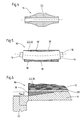
- Figures 1 to 6 show different embodiments of a roller 10 for Winding up a web of material 12, which is in particular a paper web can act.
- the roller 10 in each case comprises a base body 14, which for example has an end Pin 16 is stored accordingly.
- the flexible element 20 arranged on the base body 14 has the contact with the web Circumferential surface 22 in the region of the two roller ends 24, 24 ' greater radial compliance or less rigidity than in the middle Roll area around a resulting at maximum winding diameter To compensate for the deflection of the base body 14 at least partially.
- FIG. 1 shows a roller in a schematic, partially sectioned illustration 10 with a flexible layer 18 applied to the base body 14 and one support point 26 of higher rigidity provided in the middle roller region, in the area of which the circumferential surface 22 in contact with the web is correspondingly smaller has radial flexibility than in the region of the two roller ends 24, 24 '.
- the peripheral surface 22 in contact with the web is through a base body 14 surrounding, in particular flexible tube 28 is formed.
- This tube 28 lies directly on the stiffer support point 26 in the middle roller region. in the remaining space between the tube 28 and the base body 14 the flexible layer 18 is arranged.
- the maximum angular diameter resulting global deflection of the base body 14 at least partially compensated so that there is an at least substantially horizontal Surface line 30 results.
- the flexible layer is also in the embodiment shown in FIG 18 again between a particularly flexible tube 30 and the base body 14 provided.
- two are a distance apart in the axial direction having stiffer, in particular rigid support points 26 is provided.
- the tie rods 34 may vary Embodiment and load case axially parallel and / or approximately axially parallel to the base body 14 or crossing diagonally or helically be arranged to the base body 14.
- the tie rods 34 are the front of the Roller 10 by means of at least two outer walls 36 (only symbolic representation by means of lines), preferably diagonally or at right angles. In radial The tie rods are in the direction of the roller 10 by means of at least one spacer 38 are held in position. When using at least two spacers can be arranged according to the respective load case are.
- the base body 14 is again from surrounded a particularly flexible tube 30.
- a relatively rigid support point 26 is again provided in the roller region.
- two elastic elements having an axial distance from one another 20 arranged between the tube 30 and the base body 14.
- This elastic Elements 20 can be made of rubber, for example, or by springs, for example steel springs.
- it can be rubber-elastic annular body or over the circumference of the base body 14 extending spring assemblies or the like may be provided.
- At least in the area of the corresponding, arranged on the base body 14 flexible Elements 20 are at least two preferably symmetrically arranged tie rods 34 (only symbolic representation with dashed lines) attached.
- FIG. 4 shows a possible illustration in a schematic, partially sectioned illustration Embodiment of a roller base body 14 with a towards the ends tapered cross section.
- another support point 26 may be formed, in the area of which the circumferential surface in contact with the web again a correspondingly smaller radial compliance or has higher rigidity than in the area of the two roller ends.
- Base body 14 can, for example, have a flexible layer accordingly varying radial layer thickness or for example discrete elastic elements be applied with appropriate varying thickness. Even with the same Stiffness of the relevant layer or the relevant Elements thus have a higher flexibility towards the roller ends or less rigidity of the surface in contact with the web.
- FIG. 5 shows another in a schematic, partially sectioned illustration Embodiment of a roller 10 with successive zones in the axial direction different stiffness, for example by corresponding sections 18 'of a flexible layer or by correspondingly different flexible elements 20 can be formed.
- the web contacting surface 30 can pass directly through the flexible layer or the elastic elements can be formed. It So there is no external flexible tube provided.
- FIG. 6 shows another part in a schematic, partially sectioned illustration Embodiment of the roller 10 with one in the region of the roller ends Base body 14 applied flexible layer 18.
- This flexible layer 18 is in the present case in the area of a respective roller end between one section of the base body 14 and an outer flexible formed here for example by a rubber cover Tube 28 arranged.
- a flexible layer 18 may be applied to the base body 14, which over their axial length has a constant radial rigidity and to the respective roller end has an increasing thickness.
- the radial thickness d is the flexible one Layer 18 is greatest in the area of the relevant roller end.
- the roller can be closed at both ends by a cover 32 be one of which can be seen in Figure 6.
- the base body 14 can be provided as a hollow body. He can be made of steel, for example.
- one over the length of the surface in contact with the web has a constant rigidity (modulus of elasticity) flexible Be applied layer in the thickness from the center to the edge in Ratio of the global deflection of the base body increases.
- the edge region of the, for example, formed by a metal tube Base body be conical or parabolic.
- one over the length of the surface in contact with the web has a flexible layer which is constant in thickness be, whose rigidity from the center of the roller to the edge in relation to the global deflection of the drum drops.
- the base body can be cylindrical be executed.
- the implementation of the first variant is in particular by a rubber elastic Layer possible, which is applied in the peripheral zones within a rubber cover becomes.
- the material properties of this layer are then preferred determined by the requirement of a horizontal surface line that is as horizontal as possible.
- the implementation of the second variant would be carried out as a material layer require a variable modulus of elasticity across the web width.
- An easier one The possibility to be realized is, for example, discrete elastic To use elements or spring elements, for example, by Change the distance between these elements and / or by a different one Element stiffness the required variability of the bed stiffness enable.
- an outer tube can be pulled on (wall thickness for example 5 - 10 mm for a version made of metal, for example).
- Such one outer tube would have to be taken into account when dimensioning the spring elements.
- the spring elements can for example formed by rubber-elastic, ring-shaped bodies or, for example, as metal spring packages wound all round. There is also a preload of these elements conceivable.
- the material parameters can at least essentially can be determined or determined as follows, for example:
- the flexible layer can in particular be modeled as a homogeneous layer (edge thickness, for example 20 mm, thickness towards the center of the drum, for example, about 5 mm, length, for example, about 3000 mm) with an elastic modulus of about 1 N / mm 2 .
- This size represents a lower limit for the elasticities of polymeric materials (modulus of elasticity between 1 and 500 N / mm 2 ).
- a rubber cover can serve as a protective layer against the flexible layer.
- the result is that in this case, despite a significantly higher total deflection of the base body, the difference in the deflection of the surface in contact with the web (rubber covering) between the edge and the center has decreased significantly.
- the greater total deflection of the base body results, on the one hand, from the reduction in wall thickness of the inner body formed, for example, by a metal tube in the edge zones (conical course from, for example, 40 to, for example, 20 mm), and on the other hand from the uniformity of the paper pressure on the surface in contact with the web (see figure 7).
- FIG. 7 only the abrupt end of the flexible layer leads to a pressure peak at this point. This transition should be optimized.
Landscapes
- Registering, Tensioning, Guiding Webs, And Rollers Therefor (AREA)
- Winding Of Webs (AREA)
- Replacement Of Web Rolls (AREA)
- Rolls And Other Rotary Bodies (AREA)
- Storage Of Web-Like Or Filamentary Materials (AREA)
Abstract
Description
Bei einer zweckmäßigen praktischen Ausführungsform ist die zumindest im Bereich der beiden Walzenenden vorgesehene flexible, vorzugsweise gummielastische Schicht zwischen dem Grundkörper und dem insbesondere durch einen Gummibezug oder dergleichen gebildeten flexiblen Rohr vorgesehen.
Die flexiblen Elemente können zumindest teilweise vorgespannt sein.
- Figur 1
- eine schematische, teilweise geschnittene Darstellung einer Walze zum Aufwickeln einer Materialbahn mit einer auf den Grundkörper aufgebrachten flexiblen Schicht und einer im mittleren Walzenbereich vorgesehenen Stützstelle höherer Steifigkeit;
- Figur 2
- eine schematische, teilweise geschnittene Darstellung einer weiteren Ausführungsform der Walze mit zwei in Axialrichtung einen Abstand voneinander aufweisenden Stützstellen;
- Figur 3
- eine schematische, teilweise geschnittene Darstellung einer weiteren Ausführungsform der Walze mit mehreren, in Axialrichtung einen Abstand voneinander aufweisenden flexiblen Elementen und einer im mittleren Walzenbereich vorgesehenen Stützstelle höherer Steifigkeit;
- Figur 4
- eine schematische, teilweise geschnittene Darstellung einer möglichen Ausführungsform eines Walzengrundkörpers mit einem sich zu den Enden hin verjüngenden Querschnitt;
- Figur 5
- eine schematische, teilweise geschnittene Darstellung einer weiteren Ausführungsform der Walze mit Zonen unterschiedlicher Steifigkeit;
- Figur 6
- eine schematische, teilweise geschnittene Teildarstellung einer weiteren Ausführungsform der Walze mit einer im Bereich der Walzenenden auf dem Grundkörper aufgebrachten, zwischen diesem und einem Gummibezug angeordneten flexiblen Schicht von zum jeweiligen Walzenende hin zunehmender radialer Dicke; und
- Figur 7
- einen beispielhaften Verlauf des Papierdrucks der oberen Mantellinie der Walze beziehungsweise des Tambours entlang der Walze ausgehend vom Tambourrand zur Tambourmitte hin sowie einen beispielhaften Verlauf der vertikalen Durchbiegung der oberen Mantellinie des Tambours.
Für eine vollständige Kompensation der globalen Durchbiegung des Grundkörpers müsste dessen Kontur parabolisch ausgeführt sein. Man erkennt auch, dass das Material mit 1 N/mm2 bei den angenommenen Schichtdicken geringfügig zu steif ist. Dies wäre durch eine weitere Erhöhung der Schichtdicke in den Randbereichen beziehungsweise durch einen noch geringeren E-Modul des Materials auszugleichen.
- hochelastisch, auch nach zum Beispiel 108 Lastwechsel;
- geringe Walk-/Deformationsarbeit, trotz großer Deformation bei jeder Umdrehung;
- Temperaturbeständigkeit bis zu jener Temperatur, die durch die Deformationsarbeit entsteht;
- kostengünstige Herstellung und einfache Aufbringung auf das Rohr.
- 10
- Walze, Tambour
- 12
- Materialbahn, Papierbahn
- 14
- Grundkörper
- 16
- Zapfen
- 18
- Flexible Schicht
- 18'
- Schichtabschnitt
- 20
- Flexibles Element
- 22
- bahnberührte Umfangsfläche
- 24
- Walzenende
- 24'
- Walzenende
- 26
- Stützstelle
- 28
- Rohr
- 30
- Mantellinie
- 32
- Deckel
- 34
- Zuganker
- 36
- Außenwand
- 38
- Distanzscheibe
- d
- radiale Dicke
Claims (27)
- Walze (10) zum Aufwickeln einer Materialbahn (12), insbesondere Papierbahn, mit einem Grundkörper (14) und einer bahnberührten Umfangsfläche (22), die infolge einer entsprechenden, zumindest abschnittsweise auf den Grundkörper (14) aufgebrachten flexiblen Schicht (18) und/oder wenigstens eines entsprechenden, auf dem Grundkörper (14) angeordneten flexiblen Elements (20) im Bereich der beiden Walzenenden (24, 24') eine größere radiale Nachgiebigkeit besitzt als im mittleren Walzenbereich, um eine sich bei maximalem Wickeldurchmesser ergebende Durchbiegung des Grundkörpers (14) zumindest teilweise zu kompensieren.
- Walze nach Anspruch 1,
dadurch gekennzeichnet, dass die radiale Schicht- oder Elementdicke in Richtung der Walzenachse betrachtet unterschiedlich ist. - Walze nach Anspruch 1 oder 2,
dadurch gekennzeichnet, dass die radiale Steifigkeit der jeweiligen Schicht (18) beziehungsweise der Elemente (20) in Richtung der Walzenachse betrachtet unterschiedlich ist. - Walze nach einem der vorhergehenden Ansprüche,
dadurch gekennzeichnet, dass vorzugsweise im mittleren Walzenbereich wenigstens eine insbesondere starre Stützstelle (26) vorgesehen ist, in deren Bereich die bahnberührte Umfangsfläche (22) eine entsprechend kleinere radiale Nachgiebigkeit besitzt als im Bereich der beiden Walzenenden. - Walze nach einem der vorhergehenden Ansprüche,
dadurch gekennzeichnet, dass mehrere, in Axialrichtung einen Abstand voneinander aufweisende, insbesondere starre Stützstellen (26) vorgesehen sind, in deren Bereich die bahnberührte Umfangsfläche (22) jeweils eine entsprechend kleinere radiale Nachgiebigkeit besitzt als im Bereich der beiden Walzenenden. - Walze nach Anspruch 4 oder 5,
dadurch gekennzeichnet, dass wenigstens eine starre Stützstelle (26) zumindest teilweise durch den Grundkörper (14) selbst gebildet ist. - Walze nach einem der vorhergehenden Ansprüche,
dadurch gekennzeichnet, dass die bahnberührte Umfangsfläche (22) durch ein den Grundkörper (14) umgebendes, insbesondere flexibles Rohrs (28) gebildet und die flexible Schicht (18) beziehungsweise das flexible Element (20) radial zwischen dem Grundkörper (14) und dem Rohr (28) angeordnet ist. - Walze nach Anspruch 7,
dadurch gekennzeichnet, dass das flexible Rohr (28) durch einen Gummibezug oder dergleichen gebildet ist. - Walze nach einem der vorhergehenden Ansprüche,
dadurch gekennzeichnet, dass zumindest im Bereich der beiden Walzenenden eine flexible Schicht (18) auf den Grundkörper (14) aufgebracht ist, die über ihre axiale Länge eine konstante radiale Steifigkeit besitzt und zum jeweiligen Walzenende hin eine allgemein zunehmende Dicke (d) aufweist. - Walze nach Anspruch 9,
dadurch gekennzeichnet, dass die Dicke (d) der flexiblen Schicht (18) zum jeweiligen Walzenende hin zumindest im wesentlichen entsprechend der sich bei maximalem Wickeldurchmesser ergebenden Durchbiegung des Grundkörpers (14) zunimmt. - Walze nach Anspruch 9 oder 10,
dadurch gekennzeichnet, dass der Grundkörper (14) zum jeweiligen Walzenende hin zumindest im wesentlichen entsprechend der zunehmenden Dicke (d) der flexiblen Schicht (18) verjüngt ist. - Walze nach einem der vorhergehenden Ansprüche,
dadurch gekennzeichnet, dass die flexible Schicht (18) durch eine gummielastische Schicht gebildet ist. - Walze nach einem der vorhergehenden Ansprüche,
dadurch gekennzeichnet, dass die flexible Schicht (18) durch eine inhomogene Schicht aus geschäumtem Material und/oder einer Wabenstruktur usw. gebildet ist. - Walze nach einem der vorhergehenden Ansprüchen,
dadurch gekennzeichnet, dass die zumindest im Bereich der beiden Walzenenden vorgesehene flexible, vorzugsweise gummielastische Schicht (18) zwischen dem Grundkörper (14) und dem insbesondere durch einen Gummibezug oder dergleichen gebildeten flexiblen Rohr (28) vorgesehen ist. - Walze nach einem der vorhergehenden Ansprüche,
dadurch gekennzeichnet, dass zumindest im Bereich der beiden Walzenenden eine flexible Schicht (18) auf den Grundkörper (14) aufgebracht ist, die über ihre axiale Länge eine konstante Dicke (d) besitzt und zum jeweiligen Walzenende hin eine allgemein zunehmende radiale Nachgiebigkeit aufweist. - Walze nach einem der vorhergehenden Ansprüche,
dadurch gekennzeichnet, dass mehrere, in Axialrichtung einen Abstand voneinander aufweisende flexible Elemente (20) vorgesehen sind und zur Erzeugung der im Bereich der beiden Walzenenden im Vergleich zum mittleren Walzenbereich größeren radialen Nachgiebigkeit der bahnberührten Umfangsfläche (22) deren gegenseitige Abstände entsprechend gewählt sind und/oder deren Nachgiebigkeit entsprechend unterschiedlich ist. - Walze nach einem der vorhergehenden Ansprüche,
dadurch gekennzeichnet, dass die flexiblen Elemente (20) zumindest teilweise jeweils durch ein diskretes Federelement gebildet sind. - Walze nach Anspruch 17,
dadurch gekennzeichnet, dass die flexiblen Elemente (20) zumindest teilweise jeweils durch einen gummielastischen ringförmigen Körper gebildet sind. - Walze nach Anspruch 17 oder 18,
dadurch gekennzeichnet, dass die flexiblen Elemente (20) zumindest teilweise jeweils durch ein sich über den Umfang des Grundkörpers (14) erstreckendes Federpaket gebildet sind. - Walze nach einem der vorhergehenden Ansprüche,
dadurch gekennzeichnet, dass die flexiblen Elemente (20) zumindest teilweise vorgespannt sind. - Walze nach einem der vorhergehenden Ansprüche,
dadurch gekennzeichnet, dass der Grundkörper (14) als Hohlkörper vorgesehen ist. - Walze nach einem der vorhergehenden Ansprüche,
dadurch gekennzeichnet, dass im Bereich der zumindest abschnittsweise auf den Grundkörper (14) aufgebrachten flexiblen Schicht (18) und/oder wenigstens des entsprechenden, auf dem Grundkörper (14) angeordneten flexiblen Elements (20) mindestens zwei vorzugsweise symmetrisch angeordnete Zuganker (34) angebracht sind. - Walze nach Anspruch 22,
dadurch gekennzeichnet, dass die Zuganker (34) achsparallel und/oder annähernd achsparallel zum Grundkörper (14) angeordnet sind. - Walze nach Anspruch 22,
dadurch gekennzeichnet, dass die Zuganker (34) überkreuzend-diagonal beziehungsweise wendelförmig zum Grundkörper (14) angeordnet sind. - Walze nach einem der Ansprüche 22 bis 24,
dadurch gekennzeichnet, dass die Zuganker (34) stirnseitig der Walze (10) mittels mindestens zweier Außenwände (36) verspannt sind. - Walze nach Anspruch 25,
dadurch gekennzeichnet, dass die Zuganker (34) diagonal oder rechtwinklig verspannt sind. - Walze nach einem der Ansprüche 22 bis 26,
dadurch gekennzeichnet, dass die Zuganker (34) in radialer Richtung der Walze (10) mittels mindestens einer Distanzscheibe (38) in Position gehalten sind.
Applications Claiming Priority (2)
| Application Number | Priority Date | Filing Date | Title |
|---|---|---|---|
| DE10104195A DE10104195A1 (de) | 2001-01-31 | 2001-01-31 | Walze zum Aufwickeln einer Materialbahn |
| DE10104195 | 2001-01-31 |
Publications (3)
| Publication Number | Publication Date |
|---|---|
| EP1228993A2 true EP1228993A2 (de) | 2002-08-07 |
| EP1228993A3 EP1228993A3 (de) | 2004-01-28 |
| EP1228993B1 EP1228993B1 (de) | 2006-11-29 |
Family
ID=7672268
Family Applications (1)
| Application Number | Title | Priority Date | Filing Date |
|---|---|---|---|
| EP02000919A Expired - Lifetime EP1228993B1 (de) | 2001-01-31 | 2002-01-16 | Walze zum Aufwickeln einer Materialbahn |
Country Status (4)
| Country | Link |
|---|---|
| US (1) | US6846277B2 (de) |
| EP (1) | EP1228993B1 (de) |
| AT (1) | ATE346814T1 (de) |
| DE (2) | DE10104195A1 (de) |
Cited By (1)
| Publication number | Priority date | Publication date | Assignee | Title |
|---|---|---|---|---|
| WO2010105868A1 (de) * | 2009-03-16 | 2010-09-23 | Voith Patent Gmbh | Walze |
Families Citing this family (3)
| Publication number | Priority date | Publication date | Assignee | Title |
|---|---|---|---|---|
| US7147596B2 (en) * | 2002-02-26 | 2006-12-12 | Reynolds Ronald W | Low-mass roller or pulley |
| US20040052986A1 (en) * | 2002-09-17 | 2004-03-18 | Bank Lawrence C. | Reinforced paperboard tube |
| US11214461B2 (en) | 2015-03-25 | 2022-01-04 | Gpcp Ip Holdings Llc | Slip resistant core for holding a paper web |
Family Cites Families (29)
| Publication number | Priority date | Publication date | Assignee | Title |
|---|---|---|---|---|
| US619496A (en) | 1899-02-14 | Half to william h | ||
| US2450727A (en) | 1946-01-22 | 1948-10-05 | Fred L Haushalter | Method of resiliently mounting a roll on a shaft |
| US2741014A (en) | 1954-06-21 | 1956-04-10 | Ideal Roller And Mfg Company | Roller |
| US3019511A (en) | 1961-02-15 | 1962-02-06 | Beloit Iron Works | Crowned roll |
| US3522643A (en) | 1967-09-15 | 1970-08-04 | Bethlehem Steel Corp | Resilient table roller |
| US3750246A (en) | 1971-09-13 | 1973-08-07 | Gulf & Western Syst Co | Composite roll |
| DE2211892C3 (de) | 1972-03-11 | 1978-10-12 | Dornbusch & Co Gravieranstalt, 4150 Krefeld | Walze mit einem Walzenkern und einem diesen umgebenden Mantelrohr |
| DE2316746C3 (de) | 1973-04-04 | 1979-04-26 | Fenaro Ferch & Co Kg, 4048 Grevenbroich | Elastische Walze zur Druckbehandlung von Warenbahnen, insbesondere Papierbahnen |
| DE8033212U1 (de) * | 1980-12-13 | 1981-05-27 | Jagenberg-Werke AG, 4000 Düsseldorf | Wickelhuelse |
| DE3124616C2 (de) | 1981-06-17 | 1983-10-06 | Escher Wyss Ag, Zuerich | Walzenanordnung mit einer Durchbiegungseinstellwalze |
| DE3138365A1 (de) | 1981-09-21 | 1983-04-14 | Escher Wyss AG, Zürich | Durchbiegungseinstellwalze |
| FR2590650B1 (fr) | 1985-11-22 | 1988-02-26 | Clecim Sa | Cylindre a frette tournante deformable notamment pour un laminoir |
| FI72766C (fi) | 1986-02-13 | 1987-07-10 | Valmet Oy | Utbredningsvals eller motsvarande foer vaevnaden i en pappersmaskin samt foerfarande foer framstaellning av denna. |
| US4821384A (en) | 1987-11-05 | 1989-04-18 | Beloit Corporation | Self-loading controlled deflection roll |
| US4864343A (en) * | 1988-03-09 | 1989-09-05 | The Mead Corporation | Pressure development roll for imaging sheets employing photosensitive microcapsules |
| US5092235A (en) | 1989-05-24 | 1992-03-03 | Tektronix, Inc. | Pressure fixing and developing apparatus |
| US4974782A (en) * | 1989-11-24 | 1990-12-04 | The Mead Corporation | Pressure developer and rolls therefor having segments of elastomeric material for control of modulus of elasticity |
| FI102825B (fi) * | 1991-02-20 | 1999-02-26 | Valmet Corp | Rullausydin |
| EP0747314B1 (de) * | 1995-06-07 | 1999-08-25 | Eastman Kodak Company | Hülse zum Aufwickeln von bahnförmigem, verformbahrem Material |
| US5803398A (en) * | 1995-09-07 | 1998-09-08 | Eastman Kodak Company | Multiple durometer pressure roller |
| EP0784227A1 (de) * | 1996-01-10 | 1997-07-16 | Agfa-Gevaert N.V. | Wickelkern |
| DE19603211A1 (de) * | 1996-01-30 | 1997-07-31 | Jagenberg Papiertech Gmbh | Walze für eine Wickelmaschine |
| ATE190962T1 (de) * | 1996-01-30 | 2000-04-15 | Jagenberg Papiertech Gmbh | Walze für eine wickelmaschine |
| DE29622141U1 (de) * | 1996-12-20 | 1997-02-13 | Voith Sulzer Papiermaschinen GmbH, 89522 Heidenheim | Tambour zum Aufwickeln einer Materialbahn |
| DE19729907A1 (de) | 1997-07-12 | 1999-01-14 | Voith Sulzer Papiermasch Gmbh | Walze |
| DE29907798U1 (de) * | 1999-05-03 | 1999-08-12 | Voith Sulzer Papiertechnik Patent GmbH, 89522 Heidenheim | Wickelachse |
| DE29907795U1 (de) | 1999-05-03 | 1999-10-07 | Frerick, Andreas, 46286 Dorsten | Rasenflächen als Werbeträger |
| DE10026939A1 (de) | 1999-10-01 | 2001-12-13 | Voith Paper Patent Gmbh | Durchbiegungseinstellwalze |
| DE10036951A1 (de) * | 2000-07-28 | 2002-02-07 | Voith Paper Patent Gmbh | Verfahren und Wickelkern zur Vermeidung von Wickelfehlern in einer Materialbahn |
-
2001
- 2001-01-31 DE DE10104195A patent/DE10104195A1/de not_active Withdrawn
-
2002
- 2002-01-16 EP EP02000919A patent/EP1228993B1/de not_active Expired - Lifetime
- 2002-01-16 AT AT02000919T patent/ATE346814T1/de not_active IP Right Cessation
- 2002-01-16 DE DE50208816T patent/DE50208816D1/de not_active Expired - Fee Related
- 2002-01-31 US US10/062,832 patent/US6846277B2/en not_active Expired - Fee Related
Cited By (1)
| Publication number | Priority date | Publication date | Assignee | Title |
|---|---|---|---|---|
| WO2010105868A1 (de) * | 2009-03-16 | 2010-09-23 | Voith Patent Gmbh | Walze |
Also Published As
| Publication number | Publication date |
|---|---|
| US20020103063A1 (en) | 2002-08-01 |
| EP1228993B1 (de) | 2006-11-29 |
| US6846277B2 (en) | 2005-01-25 |
| EP1228993A3 (de) | 2004-01-28 |
| DE10104195A1 (de) | 2002-08-14 |
| DE50208816D1 (de) | 2007-01-11 |
| ATE346814T1 (de) | 2006-12-15 |
Similar Documents
| Publication | Publication Date | Title |
|---|---|---|
| DE102008008246B4 (de) | Buchsenlager mit verringertem Bauraumbedarf | |
| EP2090801B1 (de) | Luftfeder-Rollbalg | |
| DE2913120A1 (de) | Lager zur aufnahme von kompressivlasten | |
| DE4035054C2 (de) | Wickelvorrichtung für Bahnen aus Papier oder dergleichen und Walze hierfür | |
| DE2132918C3 (de) | Elastische Wellenkupplung, insbesondere Schraubenfeder-Kupplung | |
| DE4440725A1 (de) | Lageranordnung zur spielfreien Einstellung einer Welle, insbesondere einer Lenkwelle in einer Lenksäule | |
| EP1025996A1 (de) | Klischeezylinder | |
| CH636321A5 (de) | Faltmaschine zum falten von folien bzw. boegen. | |
| WO2001089909A1 (de) | Teleskopmechanismus | |
| EP1228993B1 (de) | Walze zum Aufwickeln einer Materialbahn | |
| DE69406088T2 (de) | Elastisches Gelenk mit kontrollierter axialer Festigkeit | |
| EP1729042B1 (de) | Faltenbalg für Gelenke | |
| EP1978275A2 (de) | Gelenklager, insbesondere an einem Drehgelenk zwischen einem Vorderwagen und Hinterwagen eines Gelenkbusses | |
| DE19928753A1 (de) | Elastische Walze und Verfahren zum Herstellen einer solchen | |
| DE69219923T2 (de) | Aufwickelhülse | |
| DE69600470T2 (de) | Versteifungsstruktur für Hohlwellen zum Wickeln von Materialbahnen | |
| DE19906694C2 (de) | Breitstreckwalze | |
| DE29613795U1 (de) | Walze mit optimiertem Biegeverhalten | |
| DE102017112924B4 (de) | Planetengetriebe | |
| DE19940424A1 (de) | Walze | |
| DE4428420C2 (de) | Walze zur Druckbehandlung von Warenbahnen | |
| EP2298678B1 (de) | Wickelvorrichtung | |
| WO2013075883A1 (de) | Breitstreckwalze | |
| DE10153693B4 (de) | Walze | |
| DE1425060C (de) | Zylindrische Walze mit feststehender Tragachse |
Legal Events
| Date | Code | Title | Description |
|---|---|---|---|
| PUAI | Public reference made under article 153(3) epc to a published international application that has entered the european phase |
Free format text: ORIGINAL CODE: 0009012 |
|
| AK | Designated contracting states |
Kind code of ref document: A2 Designated state(s): AT BE CH CY DE DK ES FI FR GB GR IE IT LI LU MC NL PT SE TR |
|
| AX | Request for extension of the european patent |
Free format text: AL;LT;LV;MK;RO;SI |
|
| PUAL | Search report despatched |
Free format text: ORIGINAL CODE: 0009013 |
|
| AK | Designated contracting states |
Kind code of ref document: A3 Designated state(s): AT BE CH CY DE DK ES FI FR GB GR IE IT LI LU MC NL PT SE TR |
|
| AX | Request for extension of the european patent |
Extension state: AL LT LV MK RO SI |
|
| RIC1 | Information provided on ipc code assigned before grant |
Ipc: 7B 65H 75/08 B Ipc: 7B 65H 18/00 A |
|
| 17P | Request for examination filed |
Effective date: 20040728 |
|
| AKX | Designation fees paid |
Designated state(s): AT DE FI IT SE |
|
| GRAP | Despatch of communication of intention to grant a patent |
Free format text: ORIGINAL CODE: EPIDOSNIGR1 |
|
| RAP1 | Party data changed (applicant data changed or rights of an application transferred) |
Owner name: VOITH PATENT GMBH |
|
| GRAS | Grant fee paid |
Free format text: ORIGINAL CODE: EPIDOSNIGR3 |
|
| GRAA | (expected) grant |
Free format text: ORIGINAL CODE: 0009210 |
|
| AK | Designated contracting states |
Kind code of ref document: B1 Designated state(s): AT DE FI IT SE |
|
| REF | Corresponds to: |
Ref document number: 50208816 Country of ref document: DE Date of ref document: 20070111 Kind code of ref document: P |
|
| PG25 | Lapsed in a contracting state [announced via postgrant information from national office to epo] |
Ref country code: SE Free format text: LAPSE BECAUSE OF FAILURE TO SUBMIT A TRANSLATION OF THE DESCRIPTION OR TO PAY THE FEE WITHIN THE PRESCRIBED TIME-LIMIT Effective date: 20070228 |
|
| PLBE | No opposition filed within time limit |
Free format text: ORIGINAL CODE: 0009261 |
|
| STAA | Information on the status of an ep patent application or granted ep patent |
Free format text: STATUS: NO OPPOSITION FILED WITHIN TIME LIMIT |
|
| 26N | No opposition filed |
Effective date: 20070830 |
|
| PGFP | Annual fee paid to national office [announced via postgrant information from national office to epo] |
Ref country code: DE Payment date: 20080122 Year of fee payment: 7 Ref country code: IT Payment date: 20080122 Year of fee payment: 7 |
|
| PGFP | Annual fee paid to national office [announced via postgrant information from national office to epo] |
Ref country code: AT Payment date: 20090115 Year of fee payment: 8 |
|
| PGFP | Annual fee paid to national office [announced via postgrant information from national office to epo] |
Ref country code: FI Payment date: 20090115 Year of fee payment: 8 |
|
| PG25 | Lapsed in a contracting state [announced via postgrant information from national office to epo] |
Ref country code: DE Free format text: LAPSE BECAUSE OF NON-PAYMENT OF DUE FEES Effective date: 20090801 |
|
| PG25 | Lapsed in a contracting state [announced via postgrant information from national office to epo] |
Ref country code: AT Free format text: LAPSE BECAUSE OF NON-PAYMENT OF DUE FEES Effective date: 20100116 Ref country code: FI Free format text: LAPSE BECAUSE OF NON-PAYMENT OF DUE FEES Effective date: 20100116 |
|
| PG25 | Lapsed in a contracting state [announced via postgrant information from national office to epo] |
Ref country code: IT Free format text: LAPSE BECAUSE OF NON-PAYMENT OF DUE FEES Effective date: 20090116 |