EP1228984B1 - Vertikalumlaufförderer - Google Patents
Vertikalumlaufförderer Download PDFInfo
- Publication number
- EP1228984B1 EP1228984B1 EP02001563A EP02001563A EP1228984B1 EP 1228984 B1 EP1228984 B1 EP 1228984B1 EP 02001563 A EP02001563 A EP 02001563A EP 02001563 A EP02001563 A EP 02001563A EP 1228984 B1 EP1228984 B1 EP 1228984B1
- Authority
- EP
- European Patent Office
- Prior art keywords
- traction mechanism
- traction
- members
- endless conveyor
- pulleys
- Prior art date
- Legal status (The legal status is an assumption and is not a legal conclusion. Google has not performed a legal analysis and makes no representation as to the accuracy of the status listed.)
- Expired - Lifetime
Links
Images


Classifications
-
- B—PERFORMING OPERATIONS; TRANSPORTING
- B65—CONVEYING; PACKING; STORING; HANDLING THIN OR FILAMENTARY MATERIAL
- B65G—TRANSPORT OR STORAGE DEVICES, e.g. CONVEYORS FOR LOADING OR TIPPING, SHOP CONVEYOR SYSTEMS OR PNEUMATIC TUBE CONVEYORS
- B65G17/00—Conveyors having an endless traction element, e.g. a chain, transmitting movement to a continuous or substantially-continuous load-carrying surface or to a series of individual load-carriers; Endless-chain conveyors in which the chains form the load-carrying surface
- B65G17/12—Conveyors having an endless traction element, e.g. a chain, transmitting movement to a continuous or substantially-continuous load-carrying surface or to a series of individual load-carriers; Endless-chain conveyors in which the chains form the load-carrying surface comprising a series of individual load-carriers fixed, or normally fixed, relative to traction element
- B65G17/123—Conveyors having an endless traction element, e.g. a chain, transmitting movement to a continuous or substantially-continuous load-carrying surface or to a series of individual load-carriers; Endless-chain conveyors in which the chains form the load-carrying surface comprising a series of individual load-carriers fixed, or normally fixed, relative to traction element arranged to keep the load-carriers horizontally during at least a part of the conveyor run
-
- B—PERFORMING OPERATIONS; TRANSPORTING
- B65—CONVEYING; PACKING; STORING; HANDLING THIN OR FILAMENTARY MATERIAL
- B65G—TRANSPORT OR STORAGE DEVICES, e.g. CONVEYORS FOR LOADING OR TIPPING, SHOP CONVEYOR SYSTEMS OR PNEUMATIC TUBE CONVEYORS
- B65G2201/00—Indexing codes relating to handling devices, e.g. conveyors, characterised by the type of product or load being conveyed or handled
- B65G2201/02—Articles
Definitions
- the invention relates to a circulation conveyor according to the preamble of claim 1.
- Trays are used in restaurants and canteens with food and drink or tableware conveyors used.
- WO 91/17102 also shows a similar vertical conveyor A1, which uses timing belts instead of chains.
- the invention has for its object a recycle conveyor to create what a forced alignment of the suspension fork guaranteed and works smoothly even with deflection movements.
- each link has the first Traction means a corresponding partner member of the second traction means also at the same level.
- the altitude levels of the complementary terms in each phase of the Circulation of the traction means It is possible through A horizontal support in both complementary links Maintain position and thus a fork accordingly to run horizontally.
- axles of the forks are stored in fork trucks, the in a rotating, arranged in front of the first traction Slide the guide rail.
- The corresponds to Path of the guide rail the path of the first Traction means.
- the traction means are preferably designed as rubber block belts, where a tension member on the via the drive wheels a drive toothing on the current side and on the opposite side lying side formed as rubber blocks for receiving and storage of the axes and pins of the support forks.
- the drive toothing creates a positive coupling reached between the traction device and the drive wheels and by coupling the drive wheels for the two traction means also a synchronous running of the traction means with each other.
- the arranged on the opposite side of the drive toothing Rubber blocks take the axles and journals of the fork elastic and thus dampen changes in movement when Start and stop the circulation of the traction devices. Received further the axles and pins of the support forks a radial distance to the drive wheels so that no touches and so that no wear can occur with these parts.
- a chain can also be used instead of a belt.
- This chain is made of corrosion-resistant steel, thus for the preferred application in kitchens and canteens daily cleaning without risk of corrosion can be.
- the drive wheels have a roller toothing.
- the gearing ensures that the two run in sync Rubber tracks reached.
- each Traction means via two laterally spaced drive wheels and two laterally spaced idler wheels runs.
- the overall height of the circulation conveyor can be so at a given distance between the up and down running forks and specified lifting height can be reduced.
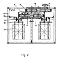
- the circulation conveyor according to FIGS. 1 and 2 comprises a frame 10, in which for the one traction device 12 two upper drive wheels 14 and two lower deflection wheels 14 and for the other Traction means 16 also two upper drive wheels 18 and two lower guide wheels 18 are mounted.
- the drive wheels 14, 18 are a drive 20 from a motor and a Gearbox driven synchronously and carry traction means 12, 16 in Form of rubber block belts from tension members with a drive toothing on the inside and made of rubber blocks formed members 22, 24 on the outward-facing Page.
- Axles 26 of support forks 28 are in pivot bearings Links 22 stored and reach through them.
- a guide rail 30 is arranged in front of the first traction means 12, the course of the path with that of the first traction means 12 matches.
- the guide rail 30 slide on rollers mounted fork carriage 32, which also.
- the support forks 28 themselves are rigid with the fork trucks 32 and through the links 22 of the first traction means 12 Axles 26 connected and have a shelf of two or more fork tines 34, on the trays with food, drinks or dishes can be parked.
- the cross-section of the drawing shows the one offset laterally Arrangement of the two traction means 12, 16 out.
- the Drive wheels 14 and deflection wheels 14 each so far apart that the axles of complementary drive wheels 14 and deflection wheels 18 just fit through the space.
- Fig. 3 shows a detail of the drive wheels 14, 18.
- rollers 42 stored within side flanges, which as Serving teeth of the drive wheels 14, 18. Enable the rollers 42 a smooth intervention in and out of the corresponding Drive teeth of the traction means 12, 16.
- the side Flanges 40 also form a side guide of the Traction means 12, 16.
- Fig. 4 shows a detail of a fork carriage 32. This includes a traveling frame 44 with a pivot bearing 46 for an axle 26 a carrying fork 28, two mounted rollers 48 for a side guide in the sectional plane of Fig. 1 and two axes Pairs of rollers 50 for lateral guidance in the cutting plane according to Fig. 2.
- the circulation conveyor can be clocked or continuous operate. Be in continuous operation the loads, e.g. B. trays with dishes on each side fed clocked via a first roller conveyor and via a second roller conveyor is removed clocked.
- the roller conveyor tracks extend into the area of the carrying forks 28, but with spaces for passing the forks 34 remain.
- the fork tines 34 lift as they pass an existing tray on the first roller conveyor and convey it along by the first traction means 12 and the Guide rail 30 predetermined orbit to the second roller conveyor. It is deposited there and then transported away.
Landscapes
- Engineering & Computer Science (AREA)
- Mechanical Engineering (AREA)
- Warehouses Or Storage Devices (AREA)
- Structure Of Belt Conveyors (AREA)
- Escalators And Moving Walkways (AREA)
- Fish Paste Products (AREA)
- Electric Cable Arrangement Between Relatively Moving Parts (AREA)
- Formation And Processing Of Food Products (AREA)
- Forklifts And Lifting Vehicles (AREA)
Description
- Fig. 1a
- einen oberen Teil eines Längsschnittes durch eine vertikale Schnittebene des Umlauf förderers,
- Fig. 1b
- einen unteren Teil eines Längsschnittes durch eine vertikale Schnittebene des Umlaufförderers,
- Fig. 2
- einen Querschnitt durch eine horizontale Schnittebene,
- Fig. 3
- ein Detailschnitt der Verzahnung der Antriebsräder und
- Fig. 4
- eine Detailansicht eines Gabelwagens.
- 10
- Gestellrahmen
- 12
- Zugmittel
- 14
- Antriebsräder, Umlenkräder
- 16
- Zugmittel
- 18
- Antriebsräder, Umlenkräder
- 20
- Antrieb
- 22
- Glieder
- 24
- Glieder
- 26
- Achse
- 28
- Traggabel
- 30
- Führungsschiene
- 32
- Gabelwagen
- 34
- Gabelzinken
- 36
- Hebel
- 38
- Zapfen
- 40
- Flansch
- 42
- Rolle
- 44
- Fahrrahmen
- 46
- Drehlager
- 48
- Rollen
- 50
- Rollenpaar
Claims (5)
- Umlaufförderer mit einem ersten in Hauptrichtung vertikal über obere und untere Antriebsräder (14) und Umlenkräder (14) laufenden formschlüssigen Zugmittel (12), insbesondere Kette oder Zahnriemen, wobei einzelne Glieder (22) des Zugmittels (12) mit Traggabeln (28) für Lasten gekoppelt sind, wobei ein zweites umlaufendes formschlüssiges Zugmittel (16) hinter dem ersten Zugmittel (12) auf gleichen Höhenniveau wie das erste Zugmittel (12) aber seitlich zum ersten Zugmittel (12) versetzt angeordnet ist, dass die Traggabeln (28) über Achsen (26) in Gliedern (22) des ersten Zugmittels (12) drehbeweglich gelagert sind, die Achsen (26) diese Glieder (22) durchgreifen und mittels eines waagerechten Hebels (36) und eines Zapfens (38) auch in Gliedern (24) des zweiten Zugmittels (16) gelagert sind und dass beide Zugmittel (12, 16) synchron umlaufen dadurch gekennzeichnet, dass die Achsen (26) der Traggabeln (28) zusätzlich in Gabelwagen (32) gelagert sind, die in einer umlaufenden, vor dem ersten Zugmittel (12) angeordneten Führungsschiene (30) gleiten, wobei der Bahnverlauf der Führungsschiene (30) dem Bahnverlauf des ersten Zugmittels (12) entspricht.
- Umlauf förderer nach Anspruch 1, dadurch gekennzeichnet, dass die Zugmittel (12, 14) als Gummiblockriemen ausgebildet sind, bei dem ein Zugträger auf der über die Antriebsräder (14, 18) laufenden Seite eine Antriebsverzahnung und auf der gegenüberliegenden Seite Glieder (22; 24) zur Aufnahme der Achsen (26) und Zapfen (38) der Traggabeln (28) aufweist.
- Umlauf förderer nach Anspruch 1, dadurch gekennzeichnet, dass die Zugmittel (12, 16) als Kette aus einem korrosionsbeständigen Stahl bestehen.
- Umlaufförderer nach einem der Ansprüche 1 bis 3, dadurch gekennzeichnet, dass die Antriebsräder (14, 18) eine Rollenverzahnung aufweisen.
- Umlaufförderer nach einem der Ansprüche 1 bis 4, dadurch gekennzeichnet, dass zur Umlenkung der Zugmittel (12, 16) im nicht angetriebenen Bereich jeweils Umlenkräder (14, 18) vorhanden sind, wobei jedes Zugmittel (12, 16) über zwei seitlich beabstandete Antriebräder (14, 18) und zwei seitlich beabstandete Umlenkräder (14, 18) läuft.
Applications Claiming Priority (2)
| Application Number | Priority Date | Filing Date | Title |
|---|---|---|---|
| DE10103720 | 2001-01-26 | ||
| DE10103720 | 2001-01-26 |
Publications (2)
| Publication Number | Publication Date |
|---|---|
| EP1228984A1 EP1228984A1 (de) | 2002-08-07 |
| EP1228984B1 true EP1228984B1 (de) | 2003-06-18 |
Family
ID=7671967
Family Applications (1)
| Application Number | Title | Priority Date | Filing Date |
|---|---|---|---|
| EP02001563A Expired - Lifetime EP1228984B1 (de) | 2001-01-26 | 2002-01-23 | Vertikalumlaufförderer |
Country Status (6)
| Country | Link |
|---|---|
| EP (1) | EP1228984B1 (de) |
| AT (1) | ATE243152T1 (de) |
| DE (1) | DE50200014D1 (de) |
| DK (1) | DK1228984T3 (de) |
| ES (1) | ES2201043T3 (de) |
| PT (1) | PT1228984E (de) |
Families Citing this family (2)
| Publication number | Priority date | Publication date | Assignee | Title |
|---|---|---|---|---|
| DE10321169A1 (de) * | 2003-05-12 | 2004-12-30 | Apparatebau Ihlbrock Gmbh | Fördereinrichtung |
| CH706243A2 (de) | 2012-03-13 | 2013-09-13 | Stefan Koepfli | Kleingutkabine für einen Speiseaufzug. |
Family Cites Families (7)
| Publication number | Priority date | Publication date | Assignee | Title |
|---|---|---|---|---|
| US1250125A (en) * | 1914-05-13 | 1917-12-18 | Joseph Baker & Sons Ltd | Apparatus for proving dough and the like. |
| JPS58148103A (ja) * | 1982-10-25 | 1983-09-03 | Hitachi Metals Ltd | 耐食チエン |
| DK116690D0 (da) * | 1990-05-10 | 1990-05-10 | Int Transport Syst Its | Apparat til at stakke/destakke kasser |
| JPH0741978B2 (ja) * | 1990-08-23 | 1995-05-10 | 株式会社椿本チエイン | 垂直ループ式仕分装置 |
| US5101963A (en) * | 1991-06-17 | 1992-04-07 | Motion Systems, Inc. | Vertical lift unit |
| JPH0544906U (ja) * | 1991-10-18 | 1993-06-15 | 株式会社椿本チエイン | 立面内で循環移動する載荷台の水平保持装置 |
| FR2683805B1 (fr) * | 1991-11-18 | 1997-11-28 | Hue Gilbert | Palettiseur automatique avec alimentation en colis par elevateur. |
-
2002
- 2002-01-23 ES ES02001563T patent/ES2201043T3/es not_active Expired - Lifetime
- 2002-01-23 DE DE50200014T patent/DE50200014D1/de not_active Expired - Lifetime
- 2002-01-23 DK DK02001563T patent/DK1228984T3/da active
- 2002-01-23 EP EP02001563A patent/EP1228984B1/de not_active Expired - Lifetime
- 2002-01-23 PT PT02001563T patent/PT1228984E/pt unknown
- 2002-01-23 AT AT02001563T patent/ATE243152T1/de not_active IP Right Cessation
Also Published As
| Publication number | Publication date |
|---|---|
| DK1228984T3 (da) | 2003-10-13 |
| ES2201043T3 (es) | 2004-03-16 |
| ATE243152T1 (de) | 2003-07-15 |
| DE50200014D1 (de) | 2003-07-24 |
| EP1228984A1 (de) | 2002-08-07 |
| PT1228984E (pt) | 2003-11-28 |
Similar Documents
| Publication | Publication Date | Title |
|---|---|---|
| DE69515983T2 (de) | Kettenbetriebener Bandförderer | |
| EP2396269B1 (de) | Vorrichtung zum befüllen von behältern | |
| EP3202689A1 (de) | Laufwagen für ein fördersystem und fördersystem mit laufwagen | |
| DE602004000785T2 (de) | Fördergerät mit Trägern | |
| DE10020608A1 (de) | Lager- und/oder Transportvorrichtung für Stückgüter | |
| DE69915560T2 (de) | Vorrichtung zum Ueberfuehren von Waren | |
| DE3623435A1 (de) | Sammelfoerderer zur aufnahme von gegenstaenden, bei dem eine abgabe des gegenstandes nur an eine aufnahmebereitete arbeitsstation erfolgt | |
| EP2921435B1 (de) | Umlenkvorrichtung für Gegenstände und Verfahren zum Umlenken von Gegenständen | |
| EP0277258B1 (de) | Vorrichtung zum Transport und zum Aufstauen von Paletten | |
| DE102011103729A1 (de) | Vorrichtung zum Fördern von Gegenständen | |
| DE10340868B4 (de) | Fördersystem, insbesondere eine Flughafengepäckförderanlage, für zum Transport von Stückgut dienenden Behältern | |
| DE3830218A1 (de) | Lagerungs- und entnahmemaschine fuer transportbehaelter | |
| EP0541850A1 (de) | Kurvengängiges Plattenband | |
| DE102014010556B4 (de) | Antriebswagen für eine Transporteinrichtung sowie Transportsystem | |
| DE10328555A1 (de) | Vorrichtung zum Ausschleusen von Lastträgern | |
| EP1228984B1 (de) | Vertikalumlaufförderer | |
| DE3616252A1 (de) | Vorrichtung zum transportieren von gegenstaenden | |
| DE3047600A1 (de) | Vorrichtung zum aufnehmen, zur lageverschiebung und zum stapeln von stabfoermigen gegenstaenden wie stangen und leisten aus holz oder dergleichen (z.b. von profilstaeben fuer bilderrahmen) | |
| DE10340867B4 (de) | Fördersystem, insbesondere eine Flughafen-Gepäckförderanlage | |
| EP0683118B1 (de) | Anordnung zum Speichern und Fördern von Gegenständen, insbesondere von Lagerbehältern | |
| DE10044048A1 (de) | Vorrichtung zum Überführen von Transportmitteln | |
| DE3445801A1 (de) | Ein- und ausschleusstation | |
| DE29710791U1 (de) | Transportsystem | |
| DE19822554C2 (de) | Transportvorrichtung | |
| DE9403889U1 (de) | Einrichtung zum Umsetzen von Fördergut |
Legal Events
| Date | Code | Title | Description |
|---|---|---|---|
| PUAI | Public reference made under article 153(3) epc to a published international application that has entered the european phase |
Free format text: ORIGINAL CODE: 0009012 |
|
| AK | Designated contracting states |
Kind code of ref document: A1 Designated state(s): AT BE CH CY DE DK ES FI FR GB GR IE IT LI LU MC NL PT SE TR |
|
| AX | Request for extension of the european patent |
Free format text: AL;LT;LV;MK;RO;SI |
|
| 17P | Request for examination filed |
Effective date: 20020807 |
|
| GRAH | Despatch of communication of intention to grant a patent |
Free format text: ORIGINAL CODE: EPIDOS IGRA |
|
| GRAH | Despatch of communication of intention to grant a patent |
Free format text: ORIGINAL CODE: EPIDOS IGRA |
|
| AKX | Designation fees paid |
Designated state(s): AT BE CH CY DE DK ES FI FR GB GR IE IT LI LU MC NL PT SE TR |
|
| GRAA | (expected) grant |
Free format text: ORIGINAL CODE: 0009210 |
|
| AK | Designated contracting states |
Designated state(s): AT BE CH CY DE DK ES FI FR GB GR IE IT LI LU MC NL PT SE TR |
|
| PG25 | Lapsed in a contracting state [announced via postgrant information from national office to epo] |
Ref country code: TR Free format text: LAPSE BECAUSE OF FAILURE TO SUBMIT A TRANSLATION OF THE DESCRIPTION OR TO PAY THE FEE WITHIN THE PRESCRIBED TIME-LIMIT Effective date: 20030618 Ref country code: CY Free format text: LAPSE BECAUSE OF FAILURE TO SUBMIT A TRANSLATION OF THE DESCRIPTION OR TO PAY THE FEE WITHIN THE PRESCRIBED TIME-LIMIT Effective date: 20030618 |
|
| REG | Reference to a national code |
Ref country code: GB Ref legal event code: FG4D Free format text: NOT ENGLISH |
|
| REG | Reference to a national code |
Ref country code: CH Ref legal event code: EP |
|
| REG | Reference to a national code |
Ref country code: IE Ref legal event code: FG4D Free format text: GERMAN |
|
| REF | Corresponds to: |
Ref document number: 50200014 Country of ref document: DE Date of ref document: 20030724 Kind code of ref document: P |
|
| GBT | Gb: translation of ep patent filed (gb section 77(6)(a)/1977) |
Effective date: 20030718 |
|
| REG | Reference to a national code |
Ref country code: SE Ref legal event code: TRGR |
|
| PG25 | Lapsed in a contracting state [announced via postgrant information from national office to epo] |
Ref country code: GR Free format text: LAPSE BECAUSE OF FAILURE TO SUBMIT A TRANSLATION OF THE DESCRIPTION OR TO PAY THE FEE WITHIN THE PRESCRIBED TIME-LIMIT Effective date: 20030918 |
|
| PGFP | Annual fee paid to national office [announced via postgrant information from national office to epo] |
Ref country code: IE Payment date: 20031120 Year of fee payment: 3 |
|
| ET | Fr: translation filed | ||
| PGFP | Annual fee paid to national office [announced via postgrant information from national office to epo] |
Ref country code: PT Payment date: 20031222 Year of fee payment: 3 |
|
| PG25 | Lapsed in a contracting state [announced via postgrant information from national office to epo] |
Ref country code: LU Free format text: LAPSE BECAUSE OF NON-PAYMENT OF DUE FEES Effective date: 20040123 |
|
| PGFP | Annual fee paid to national office [announced via postgrant information from national office to epo] |
Ref country code: FI Payment date: 20040126 Year of fee payment: 3 |
|
| PG25 | Lapsed in a contracting state [announced via postgrant information from national office to epo] |
Ref country code: MC Free format text: LAPSE BECAUSE OF NON-PAYMENT OF DUE FEES Effective date: 20040131 |
|
| REG | Reference to a national code |
Ref country code: ES Ref legal event code: FG2A Ref document number: 2201043 Country of ref document: ES Kind code of ref document: T3 |
|
| PLBE | No opposition filed within time limit |
Free format text: ORIGINAL CODE: 0009261 |
|
| STAA | Information on the status of an ep patent application or granted ep patent |
Free format text: STATUS: NO OPPOSITION FILED WITHIN TIME LIMIT |
|
| 26N | No opposition filed |
Effective date: 20040319 |
|
| PGFP | Annual fee paid to national office [announced via postgrant information from national office to epo] |
Ref country code: DK Payment date: 20050121 Year of fee payment: 4 |
|
| PG25 | Lapsed in a contracting state [announced via postgrant information from national office to epo] |
Ref country code: FI Free format text: LAPSE BECAUSE OF NON-PAYMENT OF DUE FEES Effective date: 20050123 |
|
| PG25 | Lapsed in a contracting state [announced via postgrant information from national office to epo] |
Ref country code: IE Free format text: LAPSE BECAUSE OF NON-PAYMENT OF DUE FEES Effective date: 20050124 |
|
| PGFP | Annual fee paid to national office [announced via postgrant information from national office to epo] |
Ref country code: ES Payment date: 20050124 Year of fee payment: 4 |
|
| PGFP | Annual fee paid to national office [announced via postgrant information from national office to epo] |
Ref country code: SE Payment date: 20050125 Year of fee payment: 4 |
|
| PG25 | Lapsed in a contracting state [announced via postgrant information from national office to epo] |
Ref country code: PT Free format text: LAPSE BECAUSE OF NON-PAYMENT OF DUE FEES Effective date: 20050725 |
|
| REG | Reference to a national code |
Ref country code: PT Ref legal event code: MM4A Effective date: 20050725 |
|
| REG | Reference to a national code |
Ref country code: IE Ref legal event code: MM4A |
|
| PG25 | Lapsed in a contracting state [announced via postgrant information from national office to epo] |
Ref country code: GB Free format text: LAPSE BECAUSE OF NON-PAYMENT OF DUE FEES Effective date: 20060123 |
|
| PGFP | Annual fee paid to national office [announced via postgrant information from national office to epo] |
Ref country code: AT Payment date: 20060123 Year of fee payment: 5 |
|
| PG25 | Lapsed in a contracting state [announced via postgrant information from national office to epo] |
Ref country code: ES Free format text: LAPSE BECAUSE OF NON-PAYMENT OF DUE FEES Effective date: 20060124 Ref country code: SE Free format text: LAPSE BECAUSE OF NON-PAYMENT OF DUE FEES Effective date: 20060124 |
|
| PGFP | Annual fee paid to national office [announced via postgrant information from national office to epo] |
Ref country code: BE Payment date: 20060125 Year of fee payment: 5 |
|
| PG25 | Lapsed in a contracting state [announced via postgrant information from national office to epo] |
Ref country code: DK Free format text: LAPSE BECAUSE OF NON-PAYMENT OF DUE FEES Effective date: 20060131 |
|
| PGFP | Annual fee paid to national office [announced via postgrant information from national office to epo] |
Ref country code: IT Payment date: 20060131 Year of fee payment: 5 |
|
| REG | Reference to a national code |
Ref country code: DK Ref legal event code: EBP |
|
| EUG | Se: european patent has lapsed | ||
| GBPC | Gb: european patent ceased through non-payment of renewal fee |
Effective date: 20060123 |
|
| PGFP | Annual fee paid to national office [announced via postgrant information from national office to epo] |
Ref country code: CH Payment date: 20070123 Year of fee payment: 6 |
|
| REG | Reference to a national code |
Ref country code: ES Ref legal event code: FD2A Effective date: 20060124 |
|
| PG25 | Lapsed in a contracting state [announced via postgrant information from national office to epo] |
Ref country code: AT Free format text: LAPSE BECAUSE OF NON-PAYMENT OF DUE FEES Effective date: 20070123 |
|
| BERE | Be: lapsed |
Owner name: *NERAK G.M.B.H. FORDERTECHNIK Effective date: 20070131 |
|
| PG25 | Lapsed in a contracting state [announced via postgrant information from national office to epo] |
Ref country code: BE Free format text: LAPSE BECAUSE OF NON-PAYMENT OF DUE FEES Effective date: 20070131 |
|
| PGFP | Annual fee paid to national office [announced via postgrant information from national office to epo] |
Ref country code: FR Payment date: 20070118 Year of fee payment: 6 |
|
| REG | Reference to a national code |
Ref country code: CH Ref legal event code: PL |
|
| PG25 | Lapsed in a contracting state [announced via postgrant information from national office to epo] |
Ref country code: LI Free format text: LAPSE BECAUSE OF NON-PAYMENT OF DUE FEES Effective date: 20080131 Ref country code: CH Free format text: LAPSE BECAUSE OF NON-PAYMENT OF DUE FEES Effective date: 20080131 |
|
| REG | Reference to a national code |
Ref country code: FR Ref legal event code: ST Effective date: 20081029 |
|
| PG25 | Lapsed in a contracting state [announced via postgrant information from national office to epo] |
Ref country code: FR Free format text: LAPSE BECAUSE OF NON-PAYMENT OF DUE FEES Effective date: 20080131 |
|
| PG25 | Lapsed in a contracting state [announced via postgrant information from national office to epo] |
Ref country code: IT Free format text: LAPSE BECAUSE OF NON-PAYMENT OF DUE FEES Effective date: 20070123 |
|
| PGFP | Annual fee paid to national office [announced via postgrant information from national office to epo] |
Ref country code: DE Payment date: 20130115 Year of fee payment: 12 |
|
| PGFP | Annual fee paid to national office [announced via postgrant information from national office to epo] |
Ref country code: NL Payment date: 20130121 Year of fee payment: 12 |
|
| REG | Reference to a national code |
Ref country code: DE Ref legal event code: R119 Ref document number: 50200014 Country of ref document: DE |
|
| REG | Reference to a national code |
Ref country code: NL Ref legal event code: V1 Effective date: 20140801 |
|
| REG | Reference to a national code |
Ref country code: DE Ref legal event code: R119 Ref document number: 50200014 Country of ref document: DE Effective date: 20140801 |
|
| PG25 | Lapsed in a contracting state [announced via postgrant information from national office to epo] |
Ref country code: DE Free format text: LAPSE BECAUSE OF NON-PAYMENT OF DUE FEES Effective date: 20140801 Ref country code: NL Free format text: LAPSE BECAUSE OF NON-PAYMENT OF DUE FEES Effective date: 20140801 |