EP1227015A2 - Sicherheitsgurtvorrichtung - Google Patents
Sicherheitsgurtvorrichtung Download PDFInfo
- Publication number
- EP1227015A2 EP1227015A2 EP02090029A EP02090029A EP1227015A2 EP 1227015 A2 EP1227015 A2 EP 1227015A2 EP 02090029 A EP02090029 A EP 02090029A EP 02090029 A EP02090029 A EP 02090029A EP 1227015 A2 EP1227015 A2 EP 1227015A2
- Authority
- EP
- European Patent Office
- Prior art keywords
- absorption
- seat belt
- belt device
- absorption unit
- deflection
- Prior art date
- Legal status (The legal status is an assumption and is not a legal conclusion. Google has not performed a legal analysis and makes no representation as to the accuracy of the status listed.)
- Granted
Links
Images


Classifications
-
- B—PERFORMING OPERATIONS; TRANSPORTING
- B60—VEHICLES IN GENERAL
- B60R—VEHICLES, VEHICLE FITTINGS, OR VEHICLE PARTS, NOT OTHERWISE PROVIDED FOR
- B60R22/00—Safety belts or body harnesses in vehicles
- B60R22/28—Safety belts or body harnesses in vehicles incorporating energy-absorbing devices
-
- B—PERFORMING OPERATIONS; TRANSPORTING
- B60—VEHICLES IN GENERAL
- B60R—VEHICLES, VEHICLE FITTINGS, OR VEHICLE PARTS, NOT OTHERWISE PROVIDED FOR
- B60R22/00—Safety belts or body harnesses in vehicles
- B60R22/18—Anchoring devices
- B60R2022/1818—Belt guides
-
- B—PERFORMING OPERATIONS; TRANSPORTING
- B60—VEHICLES IN GENERAL
- B60R—VEHICLES, VEHICLE FITTINGS, OR VEHICLE PARTS, NOT OTHERWISE PROVIDED FOR
- B60R22/00—Safety belts or body harnesses in vehicles
- B60R22/28—Safety belts or body harnesses in vehicles incorporating energy-absorbing devices
- B60R2022/283—Safety belts or body harnesses in vehicles incorporating energy-absorbing devices using tearing or scoring of material
-
- B—PERFORMING OPERATIONS; TRANSPORTING
- B60—VEHICLES IN GENERAL
- B60R—VEHICLES, VEHICLE FITTINGS, OR VEHICLE PARTS, NOT OTHERWISE PROVIDED FOR
- B60R22/00—Safety belts or body harnesses in vehicles
- B60R22/28—Safety belts or body harnesses in vehicles incorporating energy-absorbing devices
- B60R2022/286—Safety belts or body harnesses in vehicles incorporating energy-absorbing devices using deformation of material
-
- B—PERFORMING OPERATIONS; TRANSPORTING
- B60—VEHICLES IN GENERAL
- B60R—VEHICLES, VEHICLE FITTINGS, OR VEHICLE PARTS, NOT OTHERWISE PROVIDED FOR
- B60R22/00—Safety belts or body harnesses in vehicles
- B60R22/18—Anchoring devices
- B60R22/20—Anchoring devices adjustable in position, e.g. in height
- B60R22/201—Anchoring devices adjustable in position, e.g. in height with the belt anchor connected to a slider movable in a vehicle-mounted track
-
- B—PERFORMING OPERATIONS; TRANSPORTING
- B60—VEHICLES IN GENERAL
- B60R—VEHICLES, VEHICLE FITTINGS, OR VEHICLE PARTS, NOT OTHERWISE PROVIDED FOR
- B60R22/00—Safety belts or body harnesses in vehicles
- B60R22/18—Anchoring devices
- B60R22/24—Anchoring devices secured to the side, door, or roof of the vehicle
Definitions
- the invention relates to a seat belt device for motor vehicles with a seat belt and a deflection device for the seat belt.
- Such safety devices are generally known. At a Accident, the seat belt device must power one of the seat belts pick up held vehicle occupants. For this it is known to integrate a torsion bar in a belt retractor, which is supported by a Accidental pulling movement of the belt deformed when the retractor is blocked becomes. This type of energy absorption requires a specially trained one Retractor.
- a seat belt device to create the type mentioned at the beginning simple construction as well as safe and reliable functioning an optimal recording of the vehicle occupant in the event of an accident introduced energy guaranteed, especially without impairment the function of other components of the seat belt device.
- the deflection device with a Vehicle-attachable bracket connected via an absorption unit is, the deflection device by an accident-related pulling movement the seat belt forces relative to the bracket overcoming an opposite one from the absorption unit Absorption resistance movable in an absorption direction, in the Forces occurring during normal operation, however, on a movement in the direction of absorption is prevented, and being used to overcome the absorption resistance the absorption unit by moving in the direction of absorption moving deflector is changeable.
- a movement of the deflection device for the Energy absorption used is between the vehicle-fixed bracket and the deflection device interacting with the seat belt an absorption unit is provided, which is designed such that it prevents movement of the deflection device in normal operation, when acting on the deflection device via the seat belt Forces that occur in an accident, on the other hand, are movements of the deflection device in the absorption direction.
- the invention Absorption unit allows the kinetic in an accident Absorb energy of the vehicle occupant in that during a change in shape of the absorption unit during the movement of the deflection device he follows. This change in shape can in principle apply to any Way, for example by material deformation, material removal, Material destruction or another type of material processing. Also combinations of different types of material processing are possible according to the invention.
- the direction of absorption is preferably directed vertically downward.
- the deflection device can parallel during energy absorption to the vehicle side wall and parallel to one another between one Belt retractor and the deflecting belt section move.
- the shape change of the absorption unit is irreversible. Furthermore, the absorption unit for Shape change, at least in some areas, in particular plastically deformable his.
- the absorption unit at least part of the bracket includes.
- the absorption unit at least one in particular strip or Includes rod-shaped bending element, which is located between the deflection device and the holder preferably approximately parallel to the direction of absorption extends.
- the bending element can have an upper end on the deflection device and attached to the bracket with a lower end so that by moving the deflector towards the top of the lower end moves and in this way deformation work on the bending element is performed. It is preferred if two are parallel to one another extending bending elements are provided which face each other Sides of the seat belt are arranged.
- One of the subsections can be formed by a base part that Can be part of the bracket.
- the breaking of the connection which in normal operation is a movement of the Prevents deflection in the absorption direction, according to one Another embodiment of the invention take place in that a Absorption section of the absorption unit from a base part or the Bracket can be torn off or torn out of the base part or the bracket is.
- an absorption section the absorption unit can be deformed at the same time and by a base part or the holder is detachable.
- Another embodiment of the invention proposes that the change in shape the absorption unit is caused by material removal.
- the Material can be removed, for example, by machining material respectively.
- a preferred embodiment of the invention is that the Absorption unit at least one for changing the shape of the absorption unit has expandable recess.
- the recess can be slit-shaped be formed and extend parallel to the direction of absorption.
- the opening can be widened by that the recess delimiting material is deformed and / or removed becomes.
- the deflection device or one used to hold a deflection roller Carrier of the deflection device can into the recess with an engagement section intervene that consists of a material whose hardness is larger than that of the material delimiting the recess.
- the preferred material for the resizable section or sections the absorption unit is steel.
- the deflection device is preferably in particular on the holder performed parallel to the direction of absorption. A defined movement of the Deflection device is ensured in spite of the forces to be overcome.
- the deflection device comprises at least one deflection roller.
- the Deflection roller can cooperate with the absorption unit Carrier be stored.
- a preferred embodiment of the invention proposes a deflector to be provided with the seat belt between the deflection device and a vehicle occupant cooperates such that the Seat belt between the deflection device and the deflection element runs at least approximately parallel to the direction of absorption.
- the deflector ensures an optimal initiation of one Forces occurring in an accident via the seat belt into the deflection device.
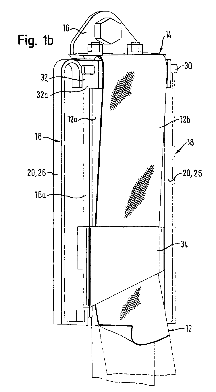
- the seat belt device shown in Figures 1a-1c includes a bracket 16, which (see FIG. 1c) has a holding section for one in the upper region has deflection device 14 explained in more detail below and in the lower Area wearing a pretensioner, on the following not closer is received.
- the continuation of a seat belt 12 is shown in Fig. 1a - 1c and in the other figures by dashed lines (leading to the occupant Section) or by dash-dotted lines (to a belt retractor leading section) lines indicated schematically.
- the bracket 16 When mounted on the vehicle, the bracket 16 is on the vehicle 42 or on the vehicle side wall 42, which is only indicated in the figures attached especially in the area of the B or C pillar. Especially from 1c shows that the holder 16 is U-shaped with a profile section Cross section of the vehicle 42 is connected.
- the deflection device 14 comprises a deflection roller 30, which is in a carrier 32 is rotatably mounted.
- the seat belt 12 runs from one not shown lower belt retractor parallel to the bracket 16 after above, is deflected by the deflecting roller 30 by approximately 180 ° and runs thus again approximately parallel to the holder 16 down to one in the normal operating state shown above the belt tensioner arranged deflector 34, from which the belt 12 during Vehicle operation leads to the respective vehicle occupant.
- the deflector 34 which is preferably fixed in height on the holder 16 is ensures that the two belt sections above the deflector 34 12a and 12b (cf. FIG. 1b) at least approximately parallel to one another run.
- the bending elements 20 each serve as an absorption section 26 absorption unit 18 formed by them.
- the absorption unit 18 is the deflection device 14 or the carrier 32 with the Bracket 16 connected.
- the carrier 32 cooperates with the holder 16 in that one vertical movement of the carrier 32 is guided by the bracket 16.
- the carrier 32 has a guide section, from which in the 1a to 1c two extending perpendicular to the axis of rotation of the deflection roller 30 Arms 32a are shown and the one vertical guide rail 16a engages around the holder 16.
- the arms 32a of the carrier 32 are the absorption sections 26 each over their upper, U-shaped connected inside bent end.
- the lower end of the bending strips 20 is angled inward like a hook, so that the bending strips 20 offset parallel to the guide rail 16a run.
- the bending elements 20 are preferably made of metal, especially made of steel.
- the strength or bending stiffness of the bending strips 20 is chosen such that that in normal operation via the belt 12 to the deflection device 14 forces acting on the strips 20 do not or at most only in a negligible Bend extent.
- the deflection device 14 is therefore prevented from moving downwards during normal operation.
- the of The absorption unit 18 formed by the strip 20 thus ensures one normal operation of the deflection device 14.
- the absorption unit 18 is designed such that, in the event of an accident, if the respective vehicle occupant suddenly due to its inertia pulls on the belt 12 and blocks the belt retractor, which hereby over the Belt 12 acting on the deflection device 14, essentially Vertical downward forces are sufficient to support the bending elements 20 deform. In the event of an accident, the deflection device 14 deforming the bending elements 20 along the guide rail 16a the bracket 16 moved vertically downward. The kinetic energy of the Vehicle occupant is thus caused by the deformation of the bending elements 20 absorbed. Generally speaking, it is at the absorption unit 18 Work done, resulting in a change in shape of the absorption unit 18 has in this way the kinetic energy of the vehicle occupant take.
- the bending elements 20 can thus energy of any size in the shortest possible way, i.e. by a comparatively short vertical path of the deflection device 14, be absorbed.
- FIG. 2 shows a variant of the invention in which the absorption unit 18 in addition to bending strips 20 serving as absorption sections 26 comprises two further strip-shaped elements, which are also referred to below as Base parts 24 are referred to.
- Fig. 2 the seat belt device is during or at the end of the Energy absorption shown.
- the deflection device 14 is located below their normal position, which they assume during normal operation.
- the bending strips 20 and the base strips are 24 fixedly together along a line-shaped nominal separation point 22 connected.
- the two strips 20, 24, for example are welded together.
- a targeted material weakening for example by forming a groove or notch to produce the target separation point 22 to be provided.
- 3a and 3b show a variant of the invention, in turn at the same time a deformation of a bending element 20 in the form of a strip trained absorption section 26 and the separation of a while 3a normal connection between the Bending strip 20 and a plate-shaped base part 24 takes place.
- the plate-shaped base part 24 a part of the bracket 16. It is also possible to part of the To provide the vehicle or the vehicle side wall itself as a base part, from which the absorption section 26 for energy absorption can be separated and on which a holder for the seat belt device is attached.
- the bending strip 20 is in the base part 24 integrated that the two parts together a continuous Form a plate.
- Fig. 3b shows, energy absorption when the Deflection device 14 moved vertically downwards, the bending strip 20 deformed on the one hand and on the other hand along the line-shaped predetermined separation points 22 similar to the lid of a canned fish, at least in part subtracted or torn from the base part 24.
- the separation according to the invention between an absorption section 26 and a base part 24 of the absorption unit 18 fixed connection which is a force in normal operation Movement of the deflection device 14 in the direction of absorption, i.e. in the shown embodiments vertically down, prevents can be designed such that the absorption section 26 from the base part 24 is torn off or torn out of the base part 24.
- FIGS. 4a and 4b Another exemplary embodiment of the invention is shown in FIGS. 4a and 4b shown.
- the only partially shown seat belt device includes a Bracket 16 with a guide rail extending in the vertical direction 16a.
- the carrier 32 of the deflection device 14, on the one Deflection roller 30 is mounted, cooperates with the guide rail 16a, by two engagement sections 48 of the carrier 32 each in one engage slot-shaped recess 28 which in the guide rail 16a is trained.
- the engagement sections 48 are seated in initial areas of the recesses 28, which correspond to the outer Shape of the engagement portions 48 are dimensioned and thus one for the Engagement sections 48 have sufficient width. Subsequent to this Areas 29 of the slots 28 are, however, narrower than the engagement sections 48, so that with respect to this in the absorption direction before the Engagement portions 48 lying slot areas 29, the engagement portions 48 are oversized.
- the absorption unit 18 is covered by the slots 28 and the guide rail 16a or of which the slots 28 delimit Material of the guide rail 16a formed.
- the deflection device 14 over the not shown If the seat belt is pulled down, the shape changes the absorption unit 18 by removing material from the guide rail 16a.
- the engaging portions 48 are able to pass through the slots 28 Cut material removal to its own width.
- the energy absorption takes place by machining material on the guide rail 16a.
- the removed material 46 is shown in FIG. 4b.
- the absorption properties of the absorption unit 18 can in particular by the number of engagement sections 48 and recesses 28, the proportions between the engaging portions 48 and Cutouts 28 and / or the choice of material for the engagement sections 48 and the areas of the guide rail delimiting the cutouts 28 16a can be set specifically.
- the carrier sections 48 engaging in the cutouts 28 the carrier 32 at the same time on the guide rail during energy absorption 16a and thus guided on the bracket 16.
- This interaction between the carrier 32 and the guide rail 16a be advantageously designed so that no additional measures required to guide the deflection device 14 on the holder 16 are.
- the deflection device could be via the absorption unit also directly connected to the vehicle or the vehicle side wall his.
- the holder in the sense of the invention is then from the means e.g. formed in the form of screw connections or welds, with which the absorption unit is attached to the vehicle.
Landscapes
- Engineering & Computer Science (AREA)
- Mechanical Engineering (AREA)
- Automotive Seat Belt Assembly (AREA)
Abstract

Description
- Fig. 1a - 1c
- verschiedene Ansichten einer Ausführungsform einer erfindungsgemäßen Sicherheitsgurtvorrichtung,
- Fig. 2
- eine perspektivische Ansicht einer Sicherheitsgurtvorrichtung gemäß einer weiteren Ausführungsform der Erfindung,
- Fig. 3a und 3b
- Ansichten einer Sicherheitsgurtvorrichtung gemäß einer weiteren Ausführungsform der Erfindung, und
- Fig: 4a und 4b
- eine Sicherheitsgurtvorrichtung gemäß einer weiteren Ausführungsform der Erfindung.
- 12
- Sicherheitsgurt
- 12a
- Gurtabschnitt
- 12b
- Gurtabschnitt
- 14
- Umlenkeinrichtung
- 16
- Halterung
- 16a
- Führungsschiene
- 18
- Absorptionseinheit
- 20
- Biegeelement
- 22
- Solltrennstelle
- 24
- Basisteil
- 26
- Absorptionsabschnitt
- 28
- Aussparung
- 29
- erweiterte Aussparung
- 30
- Umlenkrolle
- 32
- Träger
- 32a
- Arm
- 34
- Ablenkorgan
- 42
- Fahrzeug, Fahrzeugseitenwand
- 46
- weggenommenes Material
- 48
- Eingriffsabschnitt
Claims (22)
- Sicherheitsgurtvorrichtung für Kraftfahrzeuge mit einem Sicherheitsgurt (12) und einer Umlenkeinrichtung (14) für den Sicherheitsgurt (12), die mit einer am Fahrzeug befestigbaren Halterung (16) über eine Absorptionseinheit (18) verbunden ist, wobei die Umlenkeinrichtung (14) durch bei einer unfallbedingten Ziehbewegung des Sicherheitsgurtes (12) auftretende Kräfte relativ zur Halterung (16) unter Überwindung eines von der Absorptionseinheit (18) entgegengesetzten Absorptionswiderstands in einer Absorptionsrichtung bewegbar, bei im Normalbetrieb auftretenden Kräften dagegen an einer Bewegung in Absorptionsrichtung gehindert ist, und wobei zur Überwindung des Absorptionswiderstands die Absorptionseinheit (18) durch die sich in Absorptionsrichtung bewegende Umlenkeinrichtung (14) formveränderbar ist.
- Sicherheitsgurtvorrichtung nach Anspruch 1,
dadurch gekennzeichnet, daß die Absorptionsrichtung eine vertikal nach unten gerichtete Komponente aufweist und bevorzugt etwa parallel zur Vertikalen verläuft. - Sicherheitsgurtvorrichtung nach Anspruch 1 oder 2,
dadurch gekennzeichnet, daß die Formänderung der Absorptionseinheit (18) irreversibel ist. - Sicherheitsgurtvorrichtung nach einem der vorhergehenden Ansprüche,
dadurch gekennzeichnet, daß die Absorptionseinheit (18) zur Formänderung zumindest bereichsweise insbesondere plastisch verformbar ist. - Sicherheitsgurtvorrichtung nach einem der vorhergehenden Ansprüche,
dadurch gekennzeichnet, daß die Absorptionseinheit (18) zumindest einen Teil (24) der Halterung (16) umfaßt. - Sicherheitsgurtvorrichtung nach einem der vorhergehenden Ansprüche,
dadurch gekennzeichnet, daß die Absorptionseinheit (18) wenigstens ein insbesondere streifen- oder stabförmiges Biegeelement (20) umfaßt, das sich zwischen der Umlenkeinrichtung (14) und der Halterung (16) bevorzugt etwa parallel zur Absorptionsrichtung erstreckt. - Sicherheitsgurtvorrichtung nach einem der vorhergehenden Ansprüche,
dadurch gekennzeichnet, daß eine während des Normalbetriebs bestehende Verbindung zwischen wenigstens zwei Teilabschnitten (24, 26) der Absorptionseinheit (18) zur Formänderung der Absorptionseinheit (18) auftrennbar ist. - Sicherheitsgurtvorrichtung nach Anspruch 7,
dadurch gekennzeichnet, daß die Verbindung entlang zumindest einer vorgegebenen, insbesondere linienförmigen Solltrennstelle (22) auftrennbar ist. - Sicherheitsgurtvorrichtung nach einem der vorhergehenden Ansprüche,
dadurch gekennzeichnet, daß ein Absorptionsabschnitt (26) der Absorptionseinheit (18) von einem Basisteil (24) abreißbar oder aus einem Basisteil (24) herausreißbar ist. - Sicherheitsgurtvorrichtung nach einem der vorhergehenden Ansprüche,
dadurch gekennzeichnet, daß ein Basisteil (24), von dem ein Absorptionsabschnitt (26) der Absorptionseinheit (18) abtrennbar ist, ein Bestandteil der Halterung (16) ist. - Sicherheitsgurtvorrichtung nach einem der vorhergehenden Ansprüche,
dadurch gekennzeichnet, daß ein Absorptionsabschnitt (26) der Absorptionseinheit (18) gleichzeitig verformbar und von einem Basisteil (24) abtrennbar ist. - Sicherheitsgurtvorrichtung nach einem der Ansprüche 9 bis 11,
dadurch gekennzeichnet, daß das Basisteil (24) streifen- oder stabförmig ausgebildet ist und sich im Normalbetrieb parallel zu einem Absorptionsabschnitt (26) der Absorptionseinheit (18) erstreckt. - Sicherheitsgurtvorrichtung nach einem der Ansprüche 9 bis 11,
dadurch gekennzeichnet, daß das Basisteil (24) plattenförmig ausgebildet ist und insbesondere etwa parallel zur Absorptionsrichtung verläuft. - Sicherheitsgurtvorrichtung nach einem der vorhergehenden Ansprüche,
dadurch gekennzeichnet, daß die Formänderung der Absorptionseinheit (18) durch Materialwegnahme und insbesondere durch spanende Materialbearbeitung erfolgt. - Sicherheitsgurtvorrichtung nach einem der vorhergehenden Ansprüche,
dadurch gekennzeichnet, daß die Absorptionseinheit (18) wenigstens eine zur Formänderung der Absorptionseinheit (18) erweiterbare Aussparung (28) aufweist. - Sicherheitsgurtvorrichtung nach Anspruch 15,
dadurch gekennzeichnet, daß die Umlenkeinrichtung (14) mit wenigstens einem Eingriffsabschnitt (48) in die Aussparung (28) eingreift, der bezüglich eines in Absorptionsrichtung vor ihm liegenden Bereiches der Aussparung (28) überdimensioniert ist. - Sicherheitsgurtvorrichtung nach Anspruch 15 oder 16,
dadurch gekennzeichnet, daß die Aussparung (28) schlitzförmig ausgebildet ist und vorzugsweise etwa parallel zur Absorptionsrichtung verläuft. - Sicherheitsgurtvorrichtung nach einem der Ansprüche 15 bis 17,
dadurch gekennzeichnet, daß die Aussparung (28) in einem bevorzugt plattenförmigen Basisteil (24) ausgebildet ist, das vorzugsweise ein Bestandteil der Halterung (16) ist. - Sicherheitsgurtvorrichtung nach einem der vorhergehenden Ansprüche,
dadurch gekennzeichnet, daß die Größe des Absorptionswiderstands in Abhängigkeit von der Position der Umlenkeinrichtung (14) variiert und insbesondere in Absorptionsrichtung zunimmt. - Sicherheitsgurtvorrichtung nach einem der vorhergehenden Ansprüche,
dadurch gekennzeichnet, daß die Umlenkeinrichtung (14) an der Halterung (16) insbesondere parallel zur Absorptionsrichtung geführt ist. - Sicherheitsgurtvorrichtung nach einem der vorhergehenden Ansprüche,
dadurch gekennzeichnet, daß die Umlenkeinrichtung (14) zumindest eine Umlenkrolle (30) umfaßt, die vorzugsweise an einem mit der Absorptionseinheit (18) zusammenwirkenden Träger (32) gelagert ist. - Sicherheitsgurtvorrichtung nach einem der vorhergehenden Ansprüche,
dadurch gekennzeichnet, daß ein Ablenkorgan (34) vorgesehen ist, das mit dem Sicherheitsgurt (12) zwischen der Umlenkeinrichtung (14) und einem Fahrzeuginsassen derart zusammenwirkt, daß der Sicherheitsgurt (12) zwischen der Umlenkeinrichtung (14) und dem Ablenkorgan (34) zumindest näherungsweise parallel zur Absorptionsrichtung verläuft.
Applications Claiming Priority (2)
| Application Number | Priority Date | Filing Date | Title |
|---|---|---|---|
| DE10103319A DE10103319A1 (de) | 2001-01-25 | 2001-01-25 | Sicherheitsgurtvorrichtung |
| DE10103319 | 2001-01-25 |
Publications (3)
| Publication Number | Publication Date |
|---|---|
| EP1227015A2 true EP1227015A2 (de) | 2002-07-31 |
| EP1227015A3 EP1227015A3 (de) | 2004-02-11 |
| EP1227015B1 EP1227015B1 (de) | 2005-11-16 |
Family
ID=7671714
Family Applications (1)
| Application Number | Title | Priority Date | Filing Date |
|---|---|---|---|
| EP02090029A Expired - Lifetime EP1227015B1 (de) | 2001-01-25 | 2002-01-21 | Sicherheitsgurtvorrichtung |
Country Status (4)
| Country | Link |
|---|---|
| US (1) | US6736427B2 (de) |
| EP (1) | EP1227015B1 (de) |
| JP (1) | JP2002302013A (de) |
| DE (2) | DE10103319A1 (de) |
Families Citing this family (16)
| Publication number | Priority date | Publication date | Assignee | Title |
|---|---|---|---|---|
| DE10346172A1 (de) | 2003-10-01 | 2005-04-21 | Takata Petri Gmbh Ulm | Gurtumlenkeinrichtung für einen Sicherheitsgurt eines Kraftfahrzeugs |
| KR100805464B1 (ko) * | 2006-10-19 | 2008-02-20 | 현대자동차주식회사 | 시트 벨트용 랩퓨즈 벨트 |
| US8104841B2 (en) * | 2006-12-08 | 2012-01-31 | Ford Global Technologies, Llc | Energy absorbing seat anchor restraint system for child safety seats |
| JP5163009B2 (ja) * | 2007-08-21 | 2013-03-13 | マツダ株式会社 | 車両の乗員保護装置 |
| US8371425B2 (en) * | 2008-10-30 | 2013-02-12 | Ford Global Technologies, Llc | Dynamic displacement energy management device |
| US9168890B1 (en) * | 2014-09-03 | 2015-10-27 | Ford Global Technologies, Llc | Seat belt retractor with wedge clamp and load limiter |
| JP6313179B2 (ja) * | 2014-09-30 | 2018-04-18 | 本田技研工業株式会社 | 車両におけるシートベルト装置 |
| KR102496704B1 (ko) * | 2018-02-05 | 2023-02-06 | 현대자동차주식회사 | 판형 로드리미터를 이용한 안전벨트 |
| DE102020213098A1 (de) * | 2020-10-16 | 2022-04-21 | Volkswagen Aktiengesellschaft | Rückhaltevorrichtung mit einem Sicherheitsgurt und mit einem Gurtstraffer |
| US11724665B1 (en) | 2022-05-19 | 2023-08-15 | Ford Global Technologies, Llc | Load-limiting assembly for seatbelt |
| US11780404B1 (en) | 2022-05-23 | 2023-10-10 | Ford Global Technologies, Llc | Seatbelt assembly |
| US12036943B2 (en) | 2022-09-16 | 2024-07-16 | Ford Global Technologies, Llc | Load-limiting assembly for seatbelt |
| US11951932B1 (en) * | 2022-09-28 | 2024-04-09 | Ford Global Technologies, Llc | Load-limiting assembly for seatbelt |
| US12415607B2 (en) * | 2023-09-21 | 2025-09-16 | Textron Innovations Inc. | Force absorbing shoulder belt assemblies especially useful for aircraft occupant seats |
| US12428161B2 (en) | 2023-09-21 | 2025-09-30 | Textron Innovations Inc. | Force absorbing shoulder belt assemblies especially useful for aircraft occupant seats |
| DE102023133029A1 (de) * | 2023-11-27 | 2025-05-28 | Autoliv Development Ab | Sicherheitseinrichtung mit einem Kraftbegrenzer |
Family Cites Families (13)
| Publication number | Priority date | Publication date | Assignee | Title |
|---|---|---|---|---|
| GB905836A (en) * | 1959-09-01 | 1962-09-12 | Irving Air Chute Gb Ltd | Improvements in or relating to shock absorbing devices |
| FR2017493A1 (de) * | 1968-09-06 | 1970-05-22 | Seybold Rolf | |
| GB1390889A (en) * | 1973-08-03 | 1975-04-16 | Rolls Royce Motors Ltd | Energy dissipation device |
| JPS5421294Y2 (de) * | 1974-09-16 | 1979-07-28 | ||
| DE2900212A1 (de) * | 1979-01-04 | 1980-07-17 | Emil Miller | Einrichtung an sicherheitsgurten fuer kraftfahrzeuginsassen |
| DE3842791A1 (de) * | 1988-12-20 | 1990-06-28 | Daimler Benz Ag | Energieabsorbierende daempfungsvorrichtung fuer sicherheitsgurte von kraftfahrzeugen |
| US5544918A (en) * | 1994-11-08 | 1996-08-13 | Trw Vehicle Safety Systems Inc. | Seat belt webbing energy management device |
| US5700034A (en) * | 1995-09-01 | 1997-12-23 | Trw Vehicle Safety Systems Inc. | Vehicle safety apparatus with selective energy management |
| GR1003077B (el) * | 1998-01-09 | 1999-02-12 | . | Περιοριστες δυναμεως κρουσεως για πολλες χρησεις |
| DE19915024B4 (de) * | 1999-04-01 | 2013-04-25 | TAKATA Aktiengesellschaft | Sicherheitsgurtanordnung bei Fahrzeugen |
| DE19930156A1 (de) * | 1999-06-30 | 2001-01-04 | Takata Europ Gmbh | Sicherheitsgurtanordnung |
| US6394241B1 (en) * | 1999-10-21 | 2002-05-28 | Simula, Inc. | Energy absorbing shear strip bender |
| DE10011908C1 (de) * | 2000-03-11 | 2001-03-15 | Porsche Ag | Vorrichtung für einen Gurthöhenversteller eines Sicherheitsgurtsystems |
-
2001
- 2001-01-25 DE DE10103319A patent/DE10103319A1/de not_active Withdrawn
-
2002
- 2002-01-21 DE DE50204910T patent/DE50204910D1/de not_active Expired - Lifetime
- 2002-01-21 EP EP02090029A patent/EP1227015B1/de not_active Expired - Lifetime
- 2002-01-23 JP JP2002054961A patent/JP2002302013A/ja active Pending
- 2002-01-25 US US10/054,915 patent/US6736427B2/en not_active Expired - Fee Related
Also Published As
| Publication number | Publication date |
|---|---|
| DE10103319A1 (de) | 2002-08-01 |
| EP1227015B1 (de) | 2005-11-16 |
| DE50204910D1 (de) | 2005-12-22 |
| US6736427B2 (en) | 2004-05-18 |
| JP2002302013A (ja) | 2002-10-15 |
| US20020096872A1 (en) | 2002-07-25 |
| EP1227015A3 (de) | 2004-02-11 |
Similar Documents
| Publication | Publication Date | Title |
|---|---|---|
| EP2398688B1 (de) | Lenksäule für ein kraftfahrzeug | |
| DE102009059159B3 (de) | Lenksäule für ein Kraftfahrzeug | |
| EP1227015B1 (de) | Sicherheitsgurtvorrichtung | |
| DE69502398T2 (de) | Einstell- und energieaufnahmemechanismus für eine kraftfahrzeuglenksäule | |
| EP1802510B1 (de) | Verstellbare lenksäule eines kraftfahrzeuges | |
| DE69929783T2 (de) | Aufrollgurt für fahrzeuge | |
| DE2600937A1 (de) | Vorrichtung zum absorbieren von auf fahrzeuge einwirkenden stossenergien | |
| DE1755287B2 (de) | Einbauvorrichtung für Fahrzeug-Sicherheitsgurte | |
| EP3244774B1 (de) | Verbreiterbarer tisch mit crash-einzugsfunktions | |
| DE3635336C2 (de) | ||
| EP1188603A1 (de) | Zusatzverriegelung für Fahrzeugsitz-Längseinstellvorrichtung | |
| DE10294486B4 (de) | Aufprallaufnahme-Lenksäuleneinrichtung für Fahrzeuge | |
| EP1541425A1 (de) | Haltevorrichtung für eine Fahrzeugsicherheitsvorrichtung | |
| DE2722487A1 (de) | Einziehvorrichtung fuer sicherheitsgurte | |
| EP0152909B1 (de) | Vorrichtung zum selbsttätigen Aufrollen eines Fahrzeugsicherheitsgurtes | |
| DE2621198A1 (de) | Automatisch arretierende sicherheitsgurt-aufspulvorrichtung | |
| EP1501698B1 (de) | Schienenlängsführung für einen kraftfahrzeugsitz | |
| DE29622038U1 (de) | Sicherheitsgurtaufroller | |
| DE10250212B4 (de) | Schienenlängsführung für einen Kraftfahrzeugsitz | |
| EP0385289A2 (de) | Sitzführung | |
| DE2800261A1 (de) | Verankerung fuer gurtschloesser von in fahrzeugen angeordneten sicherheitsgurten | |
| DE602004008238T2 (de) | Sicherheitsvorrichtung | |
| DE19510615B4 (de) | Befestigung einer Lenksäule in einem Kraftfahrzeug | |
| DE3229260C2 (de) | Rückstrammer für ein Sicherheitsgurtsystem für Kraftfahrzeuge | |
| DE3301116A1 (de) | Verstelleinrichtung fuer fahrzeug-sitze |
Legal Events
| Date | Code | Title | Description |
|---|---|---|---|
| PUAI | Public reference made under article 153(3) epc to a published international application that has entered the european phase |
Free format text: ORIGINAL CODE: 0009012 |
|
| AK | Designated contracting states |
Kind code of ref document: A2 Designated state(s): AT BE CH CY DE DK ES FI FR GB GR IE IT LI LU MC NL PT SE TR |
|
| AX | Request for extension of the european patent |
Free format text: AL;LT;LV;MK;RO;SI |
|
| PUAL | Search report despatched |
Free format text: ORIGINAL CODE: 0009013 |
|
| AK | Designated contracting states |
Kind code of ref document: A3 Designated state(s): AT BE CH CY DE DK ES FI FR GB GR IE IT LI LU MC NL PT SE TR |
|
| AX | Request for extension of the european patent |
Extension state: AL LT LV MK RO SI |
|
| RIC1 | Information provided on ipc code assigned before grant |
Ipc: 7B 60R 22/28 A |
|
| 17P | Request for examination filed |
Effective date: 20040806 |
|
| AKX | Designation fees paid |
Designated state(s): DE FR GB SE |
|
| 17Q | First examination report despatched |
Effective date: 20041013 |
|
| GRAP | Despatch of communication of intention to grant a patent |
Free format text: ORIGINAL CODE: EPIDOSNIGR1 |
|
| GRAS | Grant fee paid |
Free format text: ORIGINAL CODE: EPIDOSNIGR3 |
|
| GRAA | (expected) grant |
Free format text: ORIGINAL CODE: 0009210 |
|
| AK | Designated contracting states |
Kind code of ref document: B1 Designated state(s): DE FR GB SE |
|
| REG | Reference to a national code |
Ref country code: GB Ref legal event code: FG4D Free format text: NOT ENGLISH |
|
| REF | Corresponds to: |
Ref document number: 50204910 Country of ref document: DE Date of ref document: 20051222 Kind code of ref document: P |
|
| REG | Reference to a national code |
Ref country code: SE Ref legal event code: TRGR |
|
| GBT | Gb: translation of ep patent filed (gb section 77(6)(a)/1977) |
Effective date: 20060206 |
|
| ET | Fr: translation filed | ||
| PLBE | No opposition filed within time limit |
Free format text: ORIGINAL CODE: 0009261 |
|
| STAA | Information on the status of an ep patent application or granted ep patent |
Free format text: STATUS: NO OPPOSITION FILED WITHIN TIME LIMIT |
|
| 26N | No opposition filed |
Effective date: 20060817 |
|
| PGFP | Annual fee paid to national office [announced via postgrant information from national office to epo] |
Ref country code: GB Payment date: 20090121 Year of fee payment: 8 |
|
| PGFP | Annual fee paid to national office [announced via postgrant information from national office to epo] |
Ref country code: SE Payment date: 20090108 Year of fee payment: 8 |
|
| GBPC | Gb: european patent ceased through non-payment of renewal fee |
Effective date: 20100121 |
|
| EUG | Se: european patent has lapsed | ||
| PG25 | Lapsed in a contracting state [announced via postgrant information from national office to epo] |
Ref country code: GB Free format text: LAPSE BECAUSE OF NON-PAYMENT OF DUE FEES Effective date: 20100121 |
|
| REG | Reference to a national code |
Ref country code: DE Ref legal event code: R082 Ref document number: 50204910 Country of ref document: DE Representative=s name: MAIKOWSKI & NINNEMANN PATENTANWAELTE, DE |
|
| PG25 | Lapsed in a contracting state [announced via postgrant information from national office to epo] |
Ref country code: SE Free format text: LAPSE BECAUSE OF NON-PAYMENT OF DUE FEES Effective date: 20100122 |
|
| REG | Reference to a national code |
Ref country code: DE Ref legal event code: R082 Ref document number: 50204910 Country of ref document: DE Representative=s name: MAIKOWSKI & NINNEMANN PATENTANWAELTE, DE Effective date: 20120904 Ref country code: DE Ref legal event code: R081 Ref document number: 50204910 Country of ref document: DE Owner name: TAKATA AKTIENGESELLSCHAFT, DE Free format text: FORMER OWNER: TAKATA-PETRI AG, 63743 ASCHAFFENBURG, DE Effective date: 20120904 Ref country code: DE Ref legal event code: R082 Ref document number: 50204910 Country of ref document: DE Representative=s name: MAIKOWSKI & NINNEMANN PATENTANWAELTE PARTNERSC, DE Effective date: 20120904 |
|
| REG | Reference to a national code |
Ref country code: FR Ref legal event code: PLFP Year of fee payment: 14 |
|
| PGFP | Annual fee paid to national office [announced via postgrant information from national office to epo] |
Ref country code: DE Payment date: 20150113 Year of fee payment: 14 |
|
| PGFP | Annual fee paid to national office [announced via postgrant information from national office to epo] |
Ref country code: FR Payment date: 20150108 Year of fee payment: 14 |
|
| REG | Reference to a national code |
Ref country code: DE Ref legal event code: R119 Ref document number: 50204910 Country of ref document: DE |
|
| REG | Reference to a national code |
Ref country code: FR Ref legal event code: ST Effective date: 20160930 |
|
| PG25 | Lapsed in a contracting state [announced via postgrant information from national office to epo] |
Ref country code: DE Free format text: LAPSE BECAUSE OF NON-PAYMENT OF DUE FEES Effective date: 20160802 |
|
| PG25 | Lapsed in a contracting state [announced via postgrant information from national office to epo] |
Ref country code: FR Free format text: LAPSE BECAUSE OF NON-PAYMENT OF DUE FEES Effective date: 20160201 |