EP1226992A1 - Dispositif d'accouplement multiple adapté à être monté comme unité de montage préassemblée - Google Patents
Dispositif d'accouplement multiple adapté à être monté comme unité de montage préassemblée Download PDFInfo
- Publication number
- EP1226992A1 EP1226992A1 EP01129357A EP01129357A EP1226992A1 EP 1226992 A1 EP1226992 A1 EP 1226992A1 EP 01129357 A EP01129357 A EP 01129357A EP 01129357 A EP01129357 A EP 01129357A EP 1226992 A1 EP1226992 A1 EP 1226992A1
- Authority
- EP
- European Patent Office
- Prior art keywords
- transmission
- combination according
- drive unit
- arrangement
- coupling device
- Prior art date
- Legal status (The legal status is an assumption and is not a legal conclusion. Google has not performed a legal analysis and makes no representation as to the accuracy of the status listed.)
- Granted
Links
Images


Classifications
-
- F—MECHANICAL ENGINEERING; LIGHTING; HEATING; WEAPONS; BLASTING
- F16—ENGINEERING ELEMENTS AND UNITS; GENERAL MEASURES FOR PRODUCING AND MAINTAINING EFFECTIVE FUNCTIONING OF MACHINES OR INSTALLATIONS; THERMAL INSULATION IN GENERAL
- F16D—COUPLINGS FOR TRANSMITTING ROTATION; CLUTCHES; BRAKES
- F16D25/00—Fluid-actuated clutches
- F16D25/06—Fluid-actuated clutches in which the fluid actuates a piston incorporated in, i.e. rotating with the clutch
- F16D25/062—Fluid-actuated clutches in which the fluid actuates a piston incorporated in, i.e. rotating with the clutch the clutch having friction surfaces
- F16D25/063—Fluid-actuated clutches in which the fluid actuates a piston incorporated in, i.e. rotating with the clutch the clutch having friction surfaces with clutch members exclusively moving axially
- F16D25/0635—Fluid-actuated clutches in which the fluid actuates a piston incorporated in, i.e. rotating with the clutch the clutch having friction surfaces with clutch members exclusively moving axially with flat friction surfaces, e.g. discs
- F16D25/0638—Fluid-actuated clutches in which the fluid actuates a piston incorporated in, i.e. rotating with the clutch the clutch having friction surfaces with clutch members exclusively moving axially with flat friction surfaces, e.g. discs with more than two discs, e.g. multiple lamellae
-
- F—MECHANICAL ENGINEERING; LIGHTING; HEATING; WEAPONS; BLASTING
- F16—ENGINEERING ELEMENTS AND UNITS; GENERAL MEASURES FOR PRODUCING AND MAINTAINING EFFECTIVE FUNCTIONING OF MACHINES OR INSTALLATIONS; THERMAL INSULATION IN GENERAL
- F16D—COUPLINGS FOR TRANSMITTING ROTATION; CLUTCHES; BRAKES
- F16D25/00—Fluid-actuated clutches
- F16D25/10—Clutch systems with a plurality of fluid-actuated clutches
-
- F—MECHANICAL ENGINEERING; LIGHTING; HEATING; WEAPONS; BLASTING
- F16—ENGINEERING ELEMENTS AND UNITS; GENERAL MEASURES FOR PRODUCING AND MAINTAINING EFFECTIVE FUNCTIONING OF MACHINES OR INSTALLATIONS; THERMAL INSULATION IN GENERAL
- F16D—COUPLINGS FOR TRANSMITTING ROTATION; CLUTCHES; BRAKES
- F16D21/00—Systems comprising a plurality of actuated clutches
- F16D21/02—Systems comprising a plurality of actuated clutches for interconnecting three or more shafts or other transmission members in different ways
- F16D21/06—Systems comprising a plurality of actuated clutches for interconnecting three or more shafts or other transmission members in different ways at least two driving shafts or two driven shafts being concentric
- F16D2021/0661—Hydraulically actuated multiple lamellae clutches
Definitions
- the invention relates generally to a multiple coupling device, possibly Double clutch device, for arrangement in a drive train of a motor vehicle between a drive unit and a transmission, wherein the clutch device is a first transmission input shaft the first clutch arrangement assigned to the transmission, possibly wet-running Multi-plate clutch assembly, and a second transmission input shaft the second clutch arrangement associated with the transmission, possibly wet-running Multi-plate clutch arrangement, for torque transmission between the drive unit and the transmission.
- the invention relates a combination of such a multiple or double clutch device, a drive unit (possibly internal combustion engine) and a gearbox designed with regard to the coupling device (especially double clutch or powershift transmission), as well as one such a combination constructed motor vehicle drive train.
- the two radially nested multi-plate clutch arrangements one each Output side with a hub part on a respective end section the assigned transmission input shaft is pushed on or becomes. That to the output side of the radially inner multi-plate clutch arrangement
- the associated hub part is in the fully assembled state of the double clutch Can be supported on the transmission input shafts in both axial directions, with a certain amount of axial play to be set during assembly.
- Support is provided in the direction of the gearbox via an axial bearing on one end face of the other, radially outer transmission input shaft and towards the drive unit via a on the radially inner transmission input shaft snap ring to be fitted after sliding on the hub part.
- For setting the length compensation for thermal expansion Serving axial play is - if necessary - between the hub part and the snap ring is fitted with at least one shim.
- the installed side serves as the input side of the double clutch one through an opening of a lid or a closure wall the input bell or input shaft which extends via a drive plate with the outer disk carrier of the radially outer Multi-plate clutch assembly is coupled as the input side of this Coupling arrangement is used.
- the hub part of the radially inner multi-plate clutch assembly and the radially inner transmission input shaft on which this hub part is pushed on or has to be pushed on Direction to the drive unit through the input hub or input shaft covered, so that the axial support towards the drive unit given snap ring cannot be fitted if the input hub or input shaft is in place.
- the double clutch When assembling the double clutch must therefore in the case of delivery of a pre-assembled double clutch the double clutch can be partially disassembled to the Attach the double clutch on the transmission side and be able to fix it axially.
- the constructions mentioned by the applicant can be done according to the Sliding on the pre-assembled double clutch as a unit a fuse securing the driving plate on the outer disk carrier or snap ring and the input hub or input shaft together drive plate welded to it can be removed. After hiring the axial play and assembly of the snap ring are these components to reassemble.
- the described, additional disassembly and Assembly steps and the game setting extensive assembly effort has correspondingly high costs for the motor vehicle manufacturer.
- the invention has for its object the assembly a coupling device of the type mentioned in the drive train to simplify and - as far as possible - without setting an axial play to get along with a length compensation for thermal expansion.
- the combination or its components at least one (possibly additional or separate) axial support device that the coupling device as a finished unit between the drive unit and the gearbox can be assembled and - if necessary with mediation the axial support device - can be positioned axially by axial Support without one or more parts of the unit in the course of Assembly process must be dismantled.
- axial support can be provided that the coupling device in the direction of Gearbox is axially supported or supportable and / or in the direction of Drive unit is axially supported or can be supported. It is preferred that it the axial support of the coupling device in the direction of Gear or / and towards the drive unit by an elastic, through at least one elastic or resilient element mediated support is.
- a wide variety of configurations are within the scope of the proposed invention possible, which can be realized alone or in combination with each other can. It is particularly preferred that the structural unit on or on the transmission side can be plugged on, so that the structural unit or coupling device can be easily installed, for example on a conveyor belt, by hand or machine.
- a fuse is preferably used activated for axial securing of the assembly, an automatic Activation of the fuse is particularly preferred.
- the fuse may include a snap or snap connection can preferably be produced without the use of a tool and a holding function exercises for the clutch.
- the snap or snap connection should be solvable for repair purposes or the like, if necessary with the help of a tool.
- an axial preload on at least one component of the Coupling device can be applied that the component and thus preferably further components of the coupling device, possibly the entire structural unit, preloaded towards the gearbox to a defined installation position guarantee.
- the assembly can move towards the gearbox supported at least one, preferably only one of the transmission input shafts or be supported.
- the coupling device can generalize the last thought or the assembly in the direction of the gearbox and / or in the direction of Drive unit mediating at least one of the transmission input shafts be axially supported or supportable.
- the transmission input shafts are nested radially, and it can an axial support of the coupling device in the direction of Gearbox and / or towards the drive unit on a radially inner or / and a radially outer transmission input shaft can be provided.
- the coupling device towards Gearbox and / or in the direction of the drive unit with the intermediation of a Oil pump drive shaft running radially within nested transmission input shafts axially supported or can be supported.
- the coupling device in the direction of Gearbox and / or towards the drive unit through the mediation Output shaft of the drive unit is axially supported or can be supported.
- the combination has a separate one from the coupling device Torsional vibration damper arrangement, which in the drive train between the coupling device and the drive unit is arranged, so can the coupling device in the direction of the gearbox and / or in the direction to the drive unit through the arrangement of the torsional vibration damper arrangement be axially supported or supportable.
- the coupling device can be a have integrated torsional vibration damper arrangement.
- the transmission usually has one Gearbox bell on which a receiving space for a clutch Are defined.
- a receiving space for the coupling device can also be provided in the case of the combination according to the invention.
- the Coupling device can then in the direction of the gearbox and / or in Direction to the drive unit through the transmission housing bell be axially supported or supportable.
- the Combination may have a lid-like closure wall, the one Opening for one associated with an input side of the coupling device Torque transmission element, possibly input hub or input shaft, the Has coupling device and in or on the gearbox bell mounted or mountable to close the recording room.
- the coupling device can move towards the transmission or / and in the direction of the drive unit by means of the closure wall be axially supported or supportable.
- an axial support of the coupling device towards the gearbox and / or towards the drive unit be provided such that the exit side of the relevant Coupling arrangement in the direction of the transmission directly or indirectly the transmission input shaft assigned to the second clutch arrangement or / and towards the drive unit directly or indirectly at the supported first clutch arrangement associated transmission input shaft is, or the output side of the clutch assembly in question in Direction to the transmission directly or indirectly on that of the first clutch arrangement assigned transmission input shaft or / and towards Drive unit directly or indirectly on the second clutch assembly assigned transmission input shaft is supported, or the output side the clutch assembly in question towards the transmission and in Direction to the drive unit directly or indirectly on this clutch assembly associated transmission input shaft is supported.
- Another option is an axial support the coupling device in the direction of the transmission or / and Direction to the drive unit via the input side, if necessary a disk carrier to provide one of the clutch arrangements, and for example, directly or indirectly on the closure wall or / and on the gearbox bell.
- a further clutch device parts enclosing outer plate carrier directly or indirectly through the mediation of only one warehouse or / and Spring arrangement axially supported on the bell housing or is supportable.
- the input side of the one clutch arrangement possibly the outer disk carrier of a radially outer one Coupling arrangements on an input side, possibly input hub or Input shaft, coupling plate coupling the coupling device directly or with the intermediation of only one bearing and / or spring arrangement the closure wall is axially supported or can be supported, namely preferably in the vicinity of or integrated with a sealing or / and Bearing arrangement between the input side of the coupling device and a wall edge delimiting the opening is.
- An elastic is preferred Means, possibly spring arrangement, provided the elastic bias or Restoring forces in the axial direction on the coupling device Applies all or at least a component thereof to the Position the coupling device axially and / or the coupling device against a gearbox-side support arrangement (possibly at least one of the transmission input shafts).
- At least one of the assembly associated component of the coupling device which has a radial support for the coupling device as a whole or at least for one Output side of one of the clutch arrangements on a transmission side
- Rotary shaft mediates and / or a rotary connection with this rotary shaft manufactures when installing the coupling device on the rotary shaft is postponed and after postponement on the rotary shaft in one or supported or supportable in both axial directions, preferably elastic is supported or can be supported without disassembly of one or several components of the assembly is required.
- Snap-in or snap-in connection can be produced, which is the axial support as well as possibly an elastic prestress in the axial direction.
- to Establishing the snap or snap connection can be at least one separate coupling element relative to the component or the rotary shaft be provided, which, after being pushed on, is simultaneously limited axially Recesses of the component and the rotary shaft engages and to enable of being pushed into an assigned recess of the component or the rotary shaft can be immersed.
- the component can do this or the rotary shaft has at least one ramp inclined surface which acts on the coupling link to slide it on and immerses it.
- the coupling element can, for example, from a coupling bracket or coupling ring, which is at least around extends part of the circumference of the rotary shaft.
- the coupling element is designed in the manner of a snap ring.
- Another Possibility is that the coupling link of a wire ring or wire bracket is formed, the several curved sections with opposite to each other Bending sense or / and several grazing, preferably at least approximately tangential to a circumference of the component or / and a circumference of the rotary shaft extending portions.
- the snap-in or snap-in connection mentioned is only one of various Possibilities.
- Another option is that the combination is a Has support arrangement after the component has been pushed on Can be mounted on the rotary shaft in association with the component and the rotary shaft is and in the assembled state the axial support of the component mediated on the rotary shaft in at least one axial direction.
- the support arrangement can on the one hand on the component and on the other hand on the Rotary shaft or a retaining element attached to it, if necessary a snap ring, attacking elastic or spring arrangement.
- this at least one spring ring include.
- the rotary shaft can / the radially outer transmission input shaft of the radial nested transmission input shafts.
- the deferred Component assigned to this transmission input shaft Coupling hub of the output side of these transmission input shafts assigned Be clutch assembly.
- the rotary shaft a / the radially inner transmission input shaft of the radially nested Transmission input shafts is.
- the push-on component a coupling hub associated with this transmission input shaft Output side of the clutch arrangement assigned to this transmission input shaft his.
- oil pump provided, so an oil pump drive shaft mediating the drive radially in the radially nested transmission input shafts run.
- this oil pump drive shaft can do the above form treated shaft, and it can be provided that the slidable component an input hub or input shaft of the Coupling device is that the input sides of both coupling arrangements assigned.
- This input hub or input shaft can on the one hand for direct or indirect coupling of the abrasion shaft of the Serve drive unit, possibly via a / the torsional vibration damper arrangement, and on the other hand the drive connection between the oil pump drive shaft and the output shaft of the drive unit.
- a sealing or closure arrangement can generally be provided be an oil flow path between the oil pump drive shaft and the Seals the input hub or input shaft in the direction of the drive unit or closes.
- the sealing or closure arrangement is preferred mountable during the assembly of the support arrangement or / and at least partially formed by the support arrangement itself.
- a preferred design that can be combined with other of the design options discussed above and below is shown is characterized in that a / the component is based on at least one another rotating shaft designed as a hollow shaft extending rotating shaft can be pushed on and on this rotary shaft in the direction of the gearbox is supported, and that one drive unit end of the other Rotary shaft axial movement and / or linear expansion play in the direction to the drive unit remains.
- This will make it easy Way for required "scope" for the end of the other rotating shaft taken care of, so that the complex adjustment of an axial play is unnecessary is.
- Effective mediator can be provided that the support in the direction conveyed to the transmission.
- a ring or Bracket element are used, the one hand in a groove of the rotary shaft or the component engages or can be brought into engagement with it and on the other hand against a stop ring surface of the component or Rotary shaft is present or can be brought into contact with the system or on both sides of one respective stop ring surface of the rotary shaft and the component or can be brought into plant.
- the ring or bracket element can be pushed axially onto the rotary shaft.
- the ring or bow element is preferably made of round wire, to avoid any voltage peaks on the possibly heavily loaded shaft as far as possible generated by sharp-edged corners or notch effects.
- the torque is transmitted between the output shaft and the input side via a torsional vibration damper arrangement (possibly of the two-mass flywheel type), so by the spherical or spherical design of the contact surfaces in a simple manner be achieved that the contact between the contact surface and the Counter-contact area with a small radius in relation to the relevant one Rotary shaft takes place, so a large system diameter is avoided.
- a torsional vibration damper arrangement possibly of the two-mass flywheel type
- the counter-contact surface can have a central axial recess in the coupling end or axially limit the input side, the counter-contact surface is preferably spherical or conical.
- the contact area and the Counter-contact surface can advantageously be based on an axis of rotation the input side or the output shaft in each case essentially rotationally symmetrical and possibly a certain self-centering function exercise relative to each other.
- the spring or elastic arrangement can be at least one disc spring or comprise at least one plate spring package.
- the support element can also itself be axially elastic or resilient; in this case, on a separate spring and elastic arrangement may not be necessary become.
- the drive unit Input side, possibly input hub or input shaft, of the coupling device by means of a spring arrangement on an output side of a Torsional vibration damper assembly or one on / the output shaft the drive unit coupled, torque transmission member axially supported or can be supported.
- the spring arrangement can, for example be formed by at least one spring ring, for example in the Kind of a disc spring.
- the input side on the one hand and the output side or the torque transmission element on the other hand can by means Take-along information is in mutual turning entrainment or be feasible, the driving formations, for example, a spline can form.
- the invention further relates to a motor vehicle drive train that consists of a combination according to the invention is constructed, as well as a multiple coupling device, if necessary, double clutch device, which is part of a Combination according to the invention can be used.
- a multiple coupling device if necessary, double coupling device for the arrangement in a motor vehicle drive train between a drive unit and a transmission, which coupling device a a first transmission input shaft of the transmission associated first clutch assembly and a second assigned to a second transmission input shaft of the transmission Coupling arrangement for torque transmission between the Drive unit and the transmission
- the coupling device is in the form of a prefabricated structural unit and as a finished unit between the drive unit and the transmission can be assembled and axially positioned by axial support without one or more parts of the assembly are disassembled during the assembly process must be, at least one compared to the unit separate axial support device provided and / or at least a component of the unit with an axial support device is executed, which is an axial support for the assembly towards
- the coupling device can correspond to the coupling device Combination according to the invention can be executed.
- the invention further relates to a set of a coupling device according to the invention and an associated axial support device for Assembly of the double clutch in a motor vehicle drive train.
- Axial support device is proposed to be designed for this is to support the coupling device in the drive train as this in connection with the combination according to the invention described for at least one of the different variants has been.
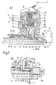
- FIG. 1 shows one in a drive train 10 between a drive unit and a transmission arranged double clutch 12.
- the transmission is in Fig. 1 by a transmission housing bell 18 limiting gear housing section 20 and two gear input shafts 22 and 24, both of which are formed as hollow shafts are, the transmission input shaft 22 is substantially extends coaxially to the transmission input shaft 24 through this.
- a pump drive shaft 26 is arranged inside the transmission input shaft 22, those for driving a transmission-side, not shown in Fig. 1 Oil pump serves.
- a closure or sealing part 180 provides for Sealing an axial bore of the input hub 36 in the direction of the drive unit.
- a clutch hub 34 serves as the input side of the double clutch 12 Made from parts 36 and 38 and through a central opening of the cover 28 extends in the direction of the drive unit and over a External teeth 42 with the torsional vibration damper, not shown is coupled.
- a driver plate or carrier plate 60 is attached to hub 34 in a rotationally fixed manner, that for torque transmission between the hub 34 and one Outer plate carrier 62 of a first plate clutch arrangement 64 serves.
- the outer disk carrier 62 extends in the direction of the transmission and radially inwards to a ring part 66 on which the outer disk carrier is rotatably attached and that by means of an axial and radial bearing arrangement 68 on the two transmission input shafts 22 and 24 is supported that both radial and axial forces on the transmission input shafts be supported.
- the axial and radial bearing assembly 68 enables a relative rotation between the ring part 66 on the one hand and both the transmission input shaft 22 and the transmission input shaft 24 on the other hand.
- the disk pack 74 of the disk pack 76 of the first Disc clutch assembly is surrounded like a ring.
- the two outer disk carriers 62 and 70 are rotatably connected to one another by the ring part 66 connected and stand together by means of an external toothing with the outer disk carrier 62 in positive torque transmission engagement standing support plate 60 with the coupling hub 34 and thus - via the torsional vibration damper, not shown - with the Crankshaft 14 of the drive unit in a torque transmission connection.
- the outer disk carriers 62 and 70 each serve as the input side for the gearbox the multi-plate clutch arrangement 64 or 72.
- a hub part 84 of an inner disk carrier 86 of the second multi-plate clutch arrangement 72 arranged in a rotationally fixed manner Relative to the control torque flow from the drive unit in The inner disk carriers 82 and 86 serve as the output side in the direction of the transmission the first or second multi-plate clutch arrangement 64 or 72nd
- actuating pistons for actuating the multi-plate clutch arrangements integrated, in the case of the embodiment shown for actuating the multi-plate clutch arrangements in the sense of an engagement.
- One assigned to the first multi-plate clutch arrangement 64 Actuating piston 110 is axially between the radially extending Portion of the outer plate carrier 62 of the first plate clutch arrangement 64 and the radially extending portion of the outer disk carrier 70 of the second multi-plate clutch arrangement 72 arranged and on both outer disk carriers and on the ring part 66 axially displaceable by means of seals and one between the outer disk carrier 62 and the actuating piston 110 formed pressure chamber and one between the actuating piston 110 and the outer disk carrier Sealing 70 trained centrifugal pressure compensation chamber guided.
- the pressure chamber is located above one formed in the ring part 66 Pressure medium channel [Bal with an assigned hydraulic master cylinder in connection, the pressure medium channel via a ring part 66 receiving, possibly gear-fixed connection sleeve on the master cylinder connected.
- the connecting sleeve and the ring part 66 form one Slewing ring.
- An actuating piston assigned to the second multi-plate clutch arrangement 72 130 is axially between the outer disk carrier 70 of the second multi-plate clutch assembly 72 and one itself radially extending and at an axial end region remote from the gear of the ring part 66 rotatably and fluid-tightly attached wall part 132 arranged and by means of seals on the outer disk carrier 70, the Wall part 132 and the ring part 66 axially displaceable and one between the outer disk carrier 70 and the actuating piston 130 Pressure chamber and one between the actuating piston 130 and the wall part 132 formed centrifugal pressure compensation chamber performed sealing.
- the pressure chamber is over another (already mentioned) pressure medium channel in a manner corresponding to the pressure chamber connected to an assigned master cylinder.
- an actuation pressure is applied to the first multi-plate clutch assembly 64 or / and the second multi-plate clutch arrangement 72 to operate in the sense of an engagement.
- diaphragm or diaphragm springs are used to disengage the clutches which the plate or diaphragm spring assigned to the actuating piston 130 is accommodated in the centrifugal pressure compensation chamber.
- the ring part 66 serve two radial bearing assemblies 90 and 92, the between the radially outer transmission input shaft 24 and the ring part 66 are effective.
- the axial mounting of the ring part 66 takes place in relation to a Support in the direction of the drive unit via the hub part 84
- the ring part 38 of the coupling hub 34 is in turn via an axial bearing 98 and a radial bearing 100 is supported on the hub part 80.
- hub part 80 via thrust bearing 94 at one end portion the radially outer transmission input shaft 24 is axially supported.
- the hub part 84 can directly on an associated stop of the transmission input shaft 24 or through the mediation of camp 92 towards Gearbox be supported on the transmission input shaft 24. Because the hub part 84 and the ring member 66 are relatively rotatable relative to each other an axial bearing may be provided between these components, if not bearing 92 has both thrust and radial bearing functions. from the latter is assumed in relation to the construction in FIG. 1.
- the assembly of the double clutch 12 according to the older construction of the Fig. 1 in the drive train, especially on the transmission, can be in the following way a pre-assembled double clutch 12 is connected to the ring part 66, the hub parts 80 and 84 and the input hub 34 on the shaft assembly 22, 24, 26 postponed.
- the snap ring 97 is not yet for this assembled or removed.
- the input hub 34 is velvet Driving plate 60 disassembled, for which purpose the retaining ring or snap ring 174 is to be solved.
- the input hub 34 together with the driving plate 60 is then mediated by Ring 74, the outer disk carrier 62, the ring member 66, the bearing 92, the hub part 84, the thrust bearing 94, the hub part 80, the built-in if necessary Shim 97 and the snap ring 96 also through the transmission input shaft 22 axially towards the drive unit supported.
- a snap ring corresponding to the snap ring 92 for axial support of the double clutch in the direction of the drive unit. Instead it is axial Support of the input hub 34 on the crankshaft flange 16 below Mediation of an elastic support arrangement provided that a Spring arrangement 200 and a spherical or spherical support element 202 includes, which in a retaining collar 204 of the input hub 34 radially inside are used and by the retaining collar 204 radially and axially also independently are held by the coupling end 16.
- the support element 202 has a spherical or spherical contact surface on the one in the fully assembled state of the drive train Counter-contact surface of an axial recess of the coupling end 16 is applied.
- the relative rotary movement of the does not occur at the contact points drawn torsional vibration damper. It is therefore a Small contact radius is provided so that the friction and the occurring occurring wear can be minimized.
- a tolerance compensation (a certain axial Clearance) can be dispensed with, as this may require several disc springs formed spring assembly 200 is provided, the axial changes in length or can absorb axial movements.
- disc springs could also be a compression spring arrangement or a combination of at least a plate spring and at least one compression spring can be used become.
- Fig. 4 shows (without claim to completeness) some suitable ones Examples. For example, you can have several disc springs in the same direction layers (see Fig. 2), layer at least two disc springs in opposite directions (see Fig. 4b), layer two sets of disc springs in opposite directions (see Fig. 4a) or combine a disc spring with a helical compression spring (see Fig. 4c).
- Fig. 4 shows (without claim to completeness) some suitable ones Examples. For example, you can have several disc springs in the same direction layers (see Fig. 2), layer at least two disc springs in opposite directions (see Fig. 4b), layer two sets of disc springs in opposite directions (see
- the axial support for the double clutch is in the direction to the drive unit alone through the arrangement 200, 202 reached. If the drive train has not yet been assembled, it is open the gearbox input shaft is fitted with a double clutch in one of the Axial direction pointing away from gearbox not secured. A transport lock the double clutch in the still open bell can can be achieved, for example, by the cover 28. Should be with the bell open a function test is carried out, the support function of the output shaft, if necessary crankshaft 14, taken over by a driving tool become.
- Fig. 3 shows an embodiment variant in which the function of the spring arrangement 200 and the support element 202 by an elastic support element 202 ', for example a rubber element, is taken over.
- the assembly this makes it particularly easy, it only needs the support element 202 'can be inserted into the retaining collar 204 before the drive train is put together.
- the support element 202 'can also perform the sealing function or take over the locking function of the element 180 according to FIG. 2.
- the variant according to FIG. 3 is in comparison to the variant according to FIG. 2 beneficial in several ways. So how becomes from the foregoing already results, the variety of components is reduced and assembly is easier. Furthermore, the elasticity of the elastic support element 202 'allows one certain compensation of a center or angular offset between the Output shaft 14 on the one hand and the transmission input shafts 22, 24 on the other hand.
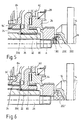
- the hub part 80 is the same as in the construction 1 via the axial bearing 94 on the radially outer transmission input shaft 24 supported. Because the axial positions of the transmission input shafts 22 and 24 both by thermal expansion and by over the gears, if necessary helical gears, from the hub parts 80, 84 initiated alternating moments are variable, can partially considerable loads on the supporting or supported components result. According to the examples in FIGS. 5 and 6, this is avoided by that between the hub part 80 and the radially outer transmission input shaft 24 a defined axial play is provided.
- the support the hub part 80 in the direction of the gearbox is no longer over the thrust bearing 94 on the radially outer transmission input shaft 24, but can have a thrust bearing that extends less radially inwards 94 'on the hub part 84.
- Another, preferred The variant is that the axial bearing 94 'has no axial support function for has the hub part 80, but that this towards the gearbox the transmission input shaft 22 is supported.
- the force transmission from that Hub part 80 in the transmission input shaft 22 can, for example, be form-fitting by means of a support ring 206, for example a round wire ring between the associated support ring surfaces of the hub part 80 on the one hand and the transmission input shaft 22 acts.
- Using a round wire ring is particularly advantageous in that that especially in the case of rounded support ring surfaces or a rounded groove in the heavily loaded transmission input shaft 22 voltage peaks acting on the shaft (e.g. due to sharp-edged Corners or notch effects) avoided or at least significantly reduced become.
- the play between the transmission input shaft 24 and the hub part 80 is dimensioned so that all expected axial displacements of the shaft 24 can be included. Remaining axial movements between the transmission input shaft 22 and the output or crankshaft 14 are in the manner described by the spring assembly 200th or the support element 202 'is elastically accommodated.
- FIG. 7 Another way of elastic axial support of the double clutch towards the drive unit (usually an internal combustion engine) is shown in Fig. 7.
- a ring-like coupling element 210 On the drive shaft 14 is a ring-like coupling element 210 with a Coupling flange 212 attached, which has a spline 42 on the Coupling hub 34 is coupled.
- One between the clutch hub 34 and the coupling flange 212 effective disc spring 214 catches axial shocks on the part of the output shaft 14 or at least dampens it. Further the disc spring 214 has the same in connection with the others Embodiments described biasing and tolerance compensation function.
- the coupling element 210 can be, for example, a flex plate Carry additional turning mass for setting one with the drive unit connected moment of inertia and rotational irregularities the drive unit is reduced.
- the additional mass can be integrated Starter ring gear.
- a torsional vibration damper arrangement can be in the double clutch be integrated and, for example, between the driving plate 60 and the outer plate carrier of the radially outer plate clutch arrangement Act.
- the double clutch can be combined with a stationary one with the double clutch in the bell housing and one Housing 216 delimiting the wet space can be designed by means of a Radial bearing 218 mounted on the coupling flange 212 and by means of a radial shaft seal 220 and a sealing ring 221 towards the drive unit is sealed.
- Exemplary embodiments for corresponding double clutches are in the German patent application filed on March 29, 2001 No.
- a torsional vibration damper assembly between the drive unit and the transmission provided, the double clutch in Direction to the drive unit through the arrangement of the torsional vibration damper arrangement be axially supported.
- a corresponding construction is shown in Fig. 8.
- a spring arrangement 222 for example a disc spring, is arranged, on the one hand for a mitigation or damping of the Crankshaft 14 originating impacts and on the other hand together with one
- Another spring assembly 224 possibly disc spring 224, for axial positioning the input hub 34 provides tolerances and axial displacements or position changes are compensated.
- the driving plate 60 and the input hub 34 are separate, via toothing 226, 228 in rotary driving engagement Parts, and the driving plate 60 is by means of a radial and axial bearing, if necessary, a collar bushing 99, mounted on the hub part 80.
- a radial and axial bearing if necessary, a collar bushing 99, mounted on the hub part 80.
- the construction shown in Fig. 8 is based on the Content of German patent application no. 101 10 145.7 of the applicant with the title “multiple coupling device” as well as the priority application (German patent application) no. 101 03 306.0 from January 25, 2001 with the title “Multiple coupling device” referred to, the disclosure of which is fully by reference in the disclosure of the present application is incorporated.
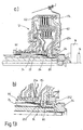
- Fig. 9 shows a solution in which the double clutch as a structural unit on the Transmission input shaft arrangement can be plugged on and without the need for partial disassembly on the transmission input shaft arrangement in the direction axially supported to the drive unit, namely on the basis of a automatically engaging or snap-in axial lock, which at present example one made of a suitable wire or the like curved, resilient securing member 230, which in an annular groove 232 in the axial end region of the radially inner transmission input shaft 22 is used and in the assembled state of the double clutch between a bias slope 234 and an axial stop 236 of the hub portion 80 engages or engages the bias slope 234.
- a automatically engaging or snap-in axial lock which at present example one made of a suitable wire or the like curved, resilient securing member 230, which in an annular groove 232 in the axial end region of the radially inner transmission input shaft 22 is used and in the assembled state of the double clutch between a bias slope 234 and an axial stop 236 of
- the securing member 230 is before the assembly of the double clutch on the Gearbox input shaft 22 pre-assembled. Then the complete Double clutch can be pushed on. A ramp is effective when pushed open 238 of the hub part 80 on the securing member 230, so that this a swiveling movement and / or an immersion movement in the groove 232, which allows the hub member 80 to pass over the Security link is pushed away.
- the axial dimensions are preferably such that in the assembled Condition the securing member 230 on the bias slope 234 under radial prestress is applied radially outward and thus an axial prestressing force on the hub part 80 and thus on the entire double clutch exercises towards the transmission.
- the one that may be referred to as the stop nose Axial stop 236 serves primarily as a centrifugal force protection, so that Prevents the fuse link from being undefined at high speeds Way out of engagement with the bias slope 234.
- the securing member can be bent in the manner shown in Fig. 9b be and several (in the present case three) bulges 240 with comparatively small bending radius and approximately in between extending tangentially to the transmission input shaft 22, in the present case have slightly curved intermediate sections 242.
- the curved Sections 240 engage the biasing slope 234 of the hub member 80 and the intermediate sections 242 lie on the groove bottom of the groove 232 on.
- the bias slope 234 Depending on how much the bias slope 234 is inclined, one becomes Disassembly of the double clutch either only comparatively strong axial Must exert tensile forces away from the gearbox (the preload slope serves then as an inclined slope, which the securing member 230 into the groove 232 immersed) or you become the input hub 34 together with the drive plate 60 have to dismantle (cf. the explanations in connection with FIG. 1; you will have to remove the circlip 174 in particular), so that the securing member 230 is removed or by a separate tool can be immersed in the groove 232 to then the double clutch subtract from the transmission input shafts.
- the bias slope 234 be comparatively is steep in order to securely fix the double clutch to the gearbox and To ensure support in the direction of the drive unit. There is the need to disassemble the input hub 34 for one If necessary, disassemble the double clutch.
- the locking member is a snap ring 230 'in an associated annular groove 232' the transmission input shaft 22 is used, which when the as Unit present double clutch with mediation of the run-up slope 238 dips into the groove 232 ', so that the hub part 80 over the resilient snap ring can be pushed away.
- the snap ring 232 ' between a ring stop of the hub part 80 in the direction of the transmission and a plurality of stops 236 'of the hub part 80 in the direction of the drive unit and is lack of space for disengaging centrifugally safe in the groove 232 'held.
- a circlip for example a rectangular one Cross-section snap ring used, so that remains Hub part 80 with respect to the snap ring 232 'through which Axial distance of the associated stops of the hub part defined axial play.
- FIGS. 11 and 12 correspond in terms of axially secure the double clutch by snapping it into place the transmission input shaft arrangement of the embodiment of FIG. 9 or the embodiment of Fig. 10. Since this snap and snap connection also an axial support of the hub part 80 in Direction to the gearbox through the axial stops 236 of the hub part 80 are guaranteed to provide a defined axial play between the radially outer transmission input shaft 24 and the hub part 80 none further measures required. It is sufficient to place the thrust bearing between the hub part 80 and the hub part 84 (thrust bearing 94 ') as in the Embodiments of FIGS. 5 and 6 less radially inward pull and the transmission input shaft 24 and the hub part 80 accordingly dimension axially.
- a snap-in or Snap connection between the hub portion 80 and the radially inner transmission input shaft 22 provided.
- Another, shown in Fig. 13 Possibility is a snap or snap connection between the Hub part 84 and the radially outer transmission input shaft 24 to be provided.
- the transmission input shaft 24 can be used in a corresponding manner an annular groove 250 into which a possibly snap ring-like or Resilient securing member 252 designed similar to link 230 is used is that when pushed on by a run-up slope of the hub part 84 is immersed in the groove 250 and in the assembled state of the double clutch engages or on between axial stops of the hub part 84 a biasing slope of the hub portion for biasing the hub portion 84 attacks towards the gearbox. It is based on the above referred to the embodiments of FIGS. 9 to 12, the are easily transferable to the embodiment of FIG. 13.
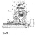
- ring part 66 which can also be referred to as an oil supply hub, defines axially position, especially axially in the direction of the drive unit 13 an additional axial bearing 254 provided that effective between the ring member 66 and the hub member 84 is.
- the double clutch 12 is in the direction of the transmission Mediation of the hub part 80 and the thrust bearing 94 on the transmission input shaft 24 supported.
- the double clutch is in the direction of the drive unit 12 through the intermediary of the ring part 66, the thrust bearing 254, the Hub part 84 and the securing member 252 on the remote from the transmission Groove boundary surface of the groove 250, that is to say on the transmission input shaft 24, supported or axially secured.
- the various components in the drivetrain between the hub part 84 and the coupling end 16 of the Output shaft 14 are arranged, are mediated by the outer disk carrier 62 and the locking ring 174 through the driving plate 60 and the input hub 34 attached thereto toward the drive unit supported and held axially on the ring member 66.
- On a snap ring on the inner transmission input shaft 22 according to the snap ring 96 according to Fig. 1 is as in the previously mentioned inventive Embodiments dispensed with.
- the double clutch can also mediate the pump drive shaft be axially supported in the direction of the drive unit.
- a snap-in or snap-in connection of the type the snap-in or snap-in connections in the exemplary embodiments 9 to 13, which are now between the input hub 34 of the double clutch and the pump drive shaft 26 is effective.
- the double clutch is pushed onto the rotary shafts 22, 24, 26 as a complete unit making the rotary driving engagement between the pump drive shaft 26 and the input hub 34.
- the pump shaft 26 has one of the the central opening of the input hub with driving teeth 34 protruding, toothless end 260 on that with a retaining groove 262 is designed for a snap ring 264.
- a sealing ring 266 between a collar 268 and the pump shaft 26 used, which the wet room towards Seals drive unit, and then a spring arrangement, possibly at least one spring ring 270 and the snap ring 264 are mounted.
- the spring arrangement which enables tolerance compensation and possibly bending-related or / and temperature-related changes in length or changes in axial position compensates, is supported by the snap ring 264 on the Pump shaft 26, which in turn by means of a not shown Bearing is supported axially.
- This storage can be in the pump or at elsewhere along the pump shaft.
- the sealing function of the seal 266 and the axial biasing function the spring arrangement 270 by means of a single component, possibly a rubber element, display.
- the spring arrangement there are various Possibilities, you could also use a serrated lock washer or use the like.
- FIG. 15 An embodiment variant of the example in FIG. 14 is shown in FIG. 15.
- a support element for example an washer, a wave spring or a plate spring 272 between a ring stop 274 of the input hub 34 and two retaining rings, possibly snap rings 276, held by one in an inner groove of the input hub 36 and the other in one External groove of the pump shaft 26 engages.
- the element 274 can have an elastic axial prestressing force are exerted on the input hub 34 in the direction of the transmission, the element 274 radially towards the drive unit inner circlip 276 and thus supported on the pump shaft 26.
- a separate cover part 278 seals the wet area of the double clutch towards the drive unit.
- the cover part 278 is under Mediation of a sealing ring 280 with the input hub 36 in sealing engagement.
- FIG. 16 Another embodiment variant is shown in FIG. 16.
- the axial support the double clutch through the input hub 36 on the Pump shaft 26 in the case of the embodiment of FIG. 16 corresponds essentially the realization in the exemplary embodiment of FIG. 14 sealing arrangement sealing the wet room in the direction of the drive unit however, here is one formed from several sealing rings 266 and 267 Seal arrangement used.
- the embodiment 16 similar to the exemplary embodiments of FIGS. 5, 6, 11, 12 ensured that the outer transmission input shaft 24 on its End has some axial play.
- the clutch is supported here by mediation of their driver plate 60 via a spring arrangement, for example a plate spring 290, and a rotary bearing 292 on the radially inner edge region the cover 28.
- the spring assembly 290 tensions the entire clutch elastic towards the gearbox, so that tolerance compensation is achieved.
- the cover 28 is on the gear housing via a locking ring 30 20 supported.
- the double clutch 12 in Direction to the drive unit on the transmission housing 20 may also be immediate support for the double clutch 12 in Direction to the drive unit on the transmission housing 20 may be provided.
- FIG. 18 is one between the outer disk carrier 62 and the gear housing 20 effective spring and pivot bearing arrangement provided that the outer disk carrier preloaded in the axial direction of the gearbox and so on the one hand enables tolerance compensation and, on the other hand, the double clutch 12 on the gearbox.
- the Outer disk carrier 62 with a radially outwardly projecting one thereof Ring collar or a support ring 300 inserted into a groove, to which a spring arrangement, possibly a plate spring 302, engages, which again via a pivot bearing 304 and possibly a locking ring 306 on Gearbox housing 20 supports.
Landscapes
- Engineering & Computer Science (AREA)
- General Engineering & Computer Science (AREA)
- Mechanical Engineering (AREA)
- Mechanical Operated Clutches (AREA)
Applications Claiming Priority (6)
| Application Number | Priority Date | Filing Date | Title |
|---|---|---|---|
| DE10103306 | 2001-01-25 | ||
| DE10103306 | 2001-01-25 | ||
| DE10115236 | 2001-03-28 | ||
| DE10115236 | 2001-03-28 | ||
| DE10131766 | 2001-06-30 | ||
| DE10131766A DE10131766A1 (de) | 2001-01-25 | 2001-06-30 | Kombination zum Aufbauen eines Antriebsstrangs mit einer Antriebseinheit, einer als vollständige Baueinheit montierbaren Mehrfach-Kupplungseinheit, einem Getriebe sowie ggf. einer Torsionsschwingungsdämpferanordnung, sowie entsprechende Kupplungsbaueinheit |
Publications (2)
| Publication Number | Publication Date |
|---|---|
| EP1226992A1 true EP1226992A1 (fr) | 2002-07-31 |
| EP1226992B1 EP1226992B1 (fr) | 2004-07-21 |
Family
ID=27214249
Family Applications (1)
| Application Number | Title | Priority Date | Filing Date |
|---|---|---|---|
| EP01129357A Revoked EP1226992B1 (fr) | 2001-01-25 | 2001-12-17 | Dispositif d'accouplement multiple adapté à être monté comme unité de montage préassemblée |
Country Status (1)
| Country | Link |
|---|---|
| EP (1) | EP1226992B1 (fr) |
Cited By (16)
| Publication number | Priority date | Publication date | Assignee | Title |
|---|---|---|---|---|
| EP1614919A2 (fr) * | 2001-10-19 | 2006-01-11 | ZF Sachs AG | Ensemble d'embrayage |
| WO2008095637A1 (fr) * | 2007-02-08 | 2008-08-14 | Borgwarner Inc. | Dispositif d'embrayage présentant un moyen de fixation destiné à la fixation du moyeu de sortie |
| WO2009059597A1 (fr) * | 2007-11-11 | 2009-05-14 | GIF Gesellschaft für Industrieforschung mbH | Transmission à double embrayage, et procédé de montage d'une transmission à double embrayage |
| JP2010504476A (ja) * | 2006-09-20 | 2010-02-12 | ジーアイエフ ゲゼルシャフト ファー インダストリエフォルツァング エムビーエイチ | メイン駆動シャフトを備えるドライブトレーン、および特にエンジンブロックから外へ延在する駆動シャフトを備える自動車用のドライブトレーン |
| WO2010081454A1 (fr) * | 2009-01-19 | 2010-07-22 | Luk Lamellen Und Kupplungsbau Beteiligungs Kg | Système à embrayages multiples |
| FR2944770A1 (fr) * | 2009-04-27 | 2010-10-29 | Peugeot Citroen Automobiles Sa | Dispositif de montage d'un organe de friction et procede de montage de l'organe sur un arbre. |
| US8162116B2 (en) | 2008-02-11 | 2012-04-24 | Schaeffler Technologies AG & Co. KG | Double clutch system |
| EP1464860B2 (fr) † | 2003-04-01 | 2012-07-25 | ZF Friedrichshafen AG | Embrayage double avec concept de palier radial |
| WO2012110018A1 (fr) * | 2011-02-16 | 2012-08-23 | Schaeffler Technologies AG & Co. KG | Dispositif de transmission de couple de rotation |
| EP2868942A1 (fr) * | 2013-10-21 | 2015-05-06 | ZF Friedrichshafen AG | Dispositif de couplage lamellaire |
| DE102014203400A1 (de) * | 2014-02-25 | 2015-08-27 | Volkswagen Aktiengesellschaft | Getriebeanordnung für ein Kraftfahrzeug |
| EP1511947B2 (fr) † | 2002-05-29 | 2017-03-15 | Dr. Ing. h.c. F. Porsche Aktiengesellschaft | Boite de vitesses pour automobile a embrayage a disques multiples a commande hydraulique |
| DE102010024150B4 (de) | 2009-07-09 | 2019-10-10 | Schaeffler Technologies AG & Co. KG | Druckverteilungskolben |
| WO2020234081A1 (fr) * | 2019-05-17 | 2020-11-26 | Transmisiones Y Equipos Mecanicos, S.A. De Cv | Chaîne cinématique dans double embrayage concentrique |
| WO2020234082A1 (fr) * | 2019-05-17 | 2020-11-26 | Transmisiones Y Equipos Mecanicos, S.A. De Cv | Unité à double embrayage dans une boîte de vitesses |
| US11859695B2 (en) | 2019-05-14 | 2024-01-02 | Transmisiones Y Equipos Mecanicos, S.A. De Cv | 8-speed gearbox |
Families Citing this family (1)
| Publication number | Priority date | Publication date | Assignee | Title |
|---|---|---|---|---|
| DE102008040172A1 (de) | 2008-07-04 | 2010-01-07 | Zf Friedrichshafen Ag | Mehrfachkupplungseinrichtung, insbesondere Doppelkupplungseinrichtung, für ein Kraftfahrzeug |
Citations (13)
| Publication number | Priority date | Publication date | Assignee | Title |
|---|---|---|---|---|
| DE2142432A1 (de) * | 1970-11-04 | 1972-05-10 | Peugeot | Scheiben Kupplung oder Bremse fur ein automatisches Stufengetriebe |
| US4732253A (en) * | 1985-08-31 | 1988-03-22 | Mitsubishi Jidosha Kogyo Kabushiki Kaisha | Power transmission |
| DE3819702A1 (de) * | 1988-06-09 | 1989-12-14 | Porsche Ag | Hydraulisch betaetigte doppelkupplung fuer ein kraftfahrzeug |
| DE4332466A1 (de) * | 1993-09-24 | 1995-03-30 | Fichtel & Sachs Ag | Doppelkupplung in geschachtelter Bauweise |
| DE4415664A1 (de) * | 1994-05-04 | 1995-11-09 | Zahnradfabrik Friedrichshafen | Kupplungsanordnung |
| US5960675A (en) * | 1992-06-25 | 1999-10-05 | Nissan Motor Co., Ltd. | Transmission |
| DE10004195A1 (de) | 1999-09-30 | 2001-04-05 | Mannesmann Sachs Ag | Mehrfach-Kupplungseinrichtung |
| DE10004189A1 (de) | 1999-09-30 | 2001-04-05 | Mannesmann Sachs Ag | Mehrfach-Kupplungseinrichtung |
| DE10004179A1 (de) | 1999-09-30 | 2001-04-05 | Mannesmann Sachs Ag | Mehrfach-Kupplungseinrichtung |
| DE10004186A1 (de) | 1999-09-30 | 2001-04-05 | Mannesmann Sachs Ag | Mehrfach-Kupplungseinrichtung |
| DE10004190A1 (de) | 1999-09-30 | 2001-04-05 | Mannesmann Sachs Ag | Mehrfach-Kupplungseinrichtung |
| DE10110145A1 (de) | 2001-01-25 | 2002-08-01 | Zf Sachs Ag | Mehrfach-Kupplungseinrichtung |
| DE10115454A1 (de) | 2001-01-25 | 2002-08-08 | Zf Sachs Ag | Mehrfach-Kupplungseinrichtung, ggf. in Kombination mit einer Torsionsschwingungsdämpferanordnung oder/und einer Elektromaschine |
-
2001
- 2001-12-17 EP EP01129357A patent/EP1226992B1/fr not_active Revoked
Patent Citations (13)
| Publication number | Priority date | Publication date | Assignee | Title |
|---|---|---|---|---|
| DE2142432A1 (de) * | 1970-11-04 | 1972-05-10 | Peugeot | Scheiben Kupplung oder Bremse fur ein automatisches Stufengetriebe |
| US4732253A (en) * | 1985-08-31 | 1988-03-22 | Mitsubishi Jidosha Kogyo Kabushiki Kaisha | Power transmission |
| DE3819702A1 (de) * | 1988-06-09 | 1989-12-14 | Porsche Ag | Hydraulisch betaetigte doppelkupplung fuer ein kraftfahrzeug |
| US5960675A (en) * | 1992-06-25 | 1999-10-05 | Nissan Motor Co., Ltd. | Transmission |
| DE4332466A1 (de) * | 1993-09-24 | 1995-03-30 | Fichtel & Sachs Ag | Doppelkupplung in geschachtelter Bauweise |
| DE4415664A1 (de) * | 1994-05-04 | 1995-11-09 | Zahnradfabrik Friedrichshafen | Kupplungsanordnung |
| DE10004195A1 (de) | 1999-09-30 | 2001-04-05 | Mannesmann Sachs Ag | Mehrfach-Kupplungseinrichtung |
| DE10004189A1 (de) | 1999-09-30 | 2001-04-05 | Mannesmann Sachs Ag | Mehrfach-Kupplungseinrichtung |
| DE10004179A1 (de) | 1999-09-30 | 2001-04-05 | Mannesmann Sachs Ag | Mehrfach-Kupplungseinrichtung |
| DE10004186A1 (de) | 1999-09-30 | 2001-04-05 | Mannesmann Sachs Ag | Mehrfach-Kupplungseinrichtung |
| DE10004190A1 (de) | 1999-09-30 | 2001-04-05 | Mannesmann Sachs Ag | Mehrfach-Kupplungseinrichtung |
| DE10110145A1 (de) | 2001-01-25 | 2002-08-01 | Zf Sachs Ag | Mehrfach-Kupplungseinrichtung |
| DE10115454A1 (de) | 2001-01-25 | 2002-08-08 | Zf Sachs Ag | Mehrfach-Kupplungseinrichtung, ggf. in Kombination mit einer Torsionsschwingungsdämpferanordnung oder/und einer Elektromaschine |
Cited By (32)
| Publication number | Priority date | Publication date | Assignee | Title |
|---|---|---|---|---|
| EP1614919A3 (fr) * | 2001-10-19 | 2006-01-18 | ZF Sachs AG | Ensemble d'embrayage |
| EP1741946A2 (fr) | 2001-10-19 | 2007-01-10 | ZF Sachs AG | Dispositif d'embrayage |
| EP1741946A3 (fr) * | 2001-10-19 | 2007-01-17 | ZF Sachs AG | Dispositif d'embrayage |
| EP1614919A2 (fr) * | 2001-10-19 | 2006-01-11 | ZF Sachs AG | Ensemble d'embrayage |
| EP1511947B2 (fr) † | 2002-05-29 | 2017-03-15 | Dr. Ing. h.c. F. Porsche Aktiengesellschaft | Boite de vitesses pour automobile a embrayage a disques multiples a commande hydraulique |
| EP1464860B2 (fr) † | 2003-04-01 | 2012-07-25 | ZF Friedrichshafen AG | Embrayage double avec concept de palier radial |
| JP2010504476A (ja) * | 2006-09-20 | 2010-02-12 | ジーアイエフ ゲゼルシャフト ファー インダストリエフォルツァング エムビーエイチ | メイン駆動シャフトを備えるドライブトレーン、および特にエンジンブロックから外へ延在する駆動シャフトを備える自動車用のドライブトレーン |
| CN101578459B (zh) * | 2007-02-08 | 2011-10-05 | 博格华纳公司 | 带有用于固定输出轮毂的紧固装置的离合器装置 |
| WO2008095637A1 (fr) * | 2007-02-08 | 2008-08-14 | Borgwarner Inc. | Dispositif d'embrayage présentant un moyen de fixation destiné à la fixation du moyeu de sortie |
| US8479906B2 (en) | 2007-02-08 | 2013-07-09 | Borgwarner Inc. | Clutch device with fastening means for fixing the output hub |
| WO2009059597A1 (fr) * | 2007-11-11 | 2009-05-14 | GIF Gesellschaft für Industrieforschung mbH | Transmission à double embrayage, et procédé de montage d'une transmission à double embrayage |
| GB2466610B (en) * | 2007-11-11 | 2012-04-04 | Saic Motor Corp Ltd | Double-clutch transmission and method for assembling a double-clutch transmission |
| AU2008324606B2 (en) * | 2007-11-11 | 2013-04-04 | Saic Motor Corporation Limited | Double-clutch transmission and method for assembling a double-clutch transmission |
| GB2466610A (en) * | 2007-11-11 | 2010-06-30 | Saic Motor Corp Ltd | Double-clutch transmission and method for assembling a double-clutch transmission |
| US8672109B2 (en) | 2007-11-11 | 2014-03-18 | Saic Motor Corporation Limited | Double clutch transmission and double clutch transmission assembly method |
| US8162116B2 (en) | 2008-02-11 | 2012-04-24 | Schaeffler Technologies AG & Co. KG | Double clutch system |
| CN102227573A (zh) * | 2009-01-19 | 2011-10-26 | 舍弗勒技术两合公司 | 多离合器装置 |
| WO2010081454A1 (fr) * | 2009-01-19 | 2010-07-22 | Luk Lamellen Und Kupplungsbau Beteiligungs Kg | Système à embrayages multiples |
| US8297422B2 (en) | 2009-01-19 | 2012-10-30 | Schaeffler Technologies AG & Co. KG | Multiple clutch device |
| CN102227573B (zh) * | 2009-01-19 | 2014-04-23 | 舍弗勒技术股份两合公司 | 多离合器装置 |
| WO2010125278A1 (fr) * | 2009-04-27 | 2010-11-04 | Peugeot Citroën Automobiles SA | Dispositif de montage d'un organe de friction et procédé de montage de l'organe sur un arbre |
| FR2944770A1 (fr) * | 2009-04-27 | 2010-10-29 | Peugeot Citroen Automobiles Sa | Dispositif de montage d'un organe de friction et procede de montage de l'organe sur un arbre. |
| DE102010024150B4 (de) | 2009-07-09 | 2019-10-10 | Schaeffler Technologies AG & Co. KG | Druckverteilungskolben |
| WO2012110018A1 (fr) * | 2011-02-16 | 2012-08-23 | Schaeffler Technologies AG & Co. KG | Dispositif de transmission de couple de rotation |
| CN103534503B (zh) * | 2011-02-16 | 2017-03-01 | 舍弗勒技术股份两合公司 | 转矩传递装置 |
| CN103534503A (zh) * | 2011-02-16 | 2014-01-22 | 舍弗勒技术股份两合公司 | 转矩传递装置 |
| EP2868942A1 (fr) * | 2013-10-21 | 2015-05-06 | ZF Friedrichshafen AG | Dispositif de couplage lamellaire |
| DE102014203400A1 (de) * | 2014-02-25 | 2015-08-27 | Volkswagen Aktiengesellschaft | Getriebeanordnung für ein Kraftfahrzeug |
| US11859695B2 (en) | 2019-05-14 | 2024-01-02 | Transmisiones Y Equipos Mecanicos, S.A. De Cv | 8-speed gearbox |
| WO2020234081A1 (fr) * | 2019-05-17 | 2020-11-26 | Transmisiones Y Equipos Mecanicos, S.A. De Cv | Chaîne cinématique dans double embrayage concentrique |
| WO2020234082A1 (fr) * | 2019-05-17 | 2020-11-26 | Transmisiones Y Equipos Mecanicos, S.A. De Cv | Unité à double embrayage dans une boîte de vitesses |
| US11649861B2 (en) | 2019-05-17 | 2023-05-16 | Transmisiones Y Equipos Mecanicos, S.A. De Cv | Double clutch unit in a transmission |
Also Published As
| Publication number | Publication date |
|---|---|
| EP1226992B1 (fr) | 2004-07-21 |
Similar Documents
| Publication | Publication Date | Title |
|---|---|---|
| DE10131766A1 (de) | Kombination zum Aufbauen eines Antriebsstrangs mit einer Antriebseinheit, einer als vollständige Baueinheit montierbaren Mehrfach-Kupplungseinheit, einem Getriebe sowie ggf. einer Torsionsschwingungsdämpferanordnung, sowie entsprechende Kupplungsbaueinheit | |
| DE102005037514B4 (de) | Drehmomentübertragungseinrichtung | |
| DE112011105537B4 (de) | Trockene Doppelkupplung | |
| EP2109722B1 (fr) | Dispositif de transmission de couple | |
| DE112008000154B4 (de) | Drehmomentübertragungseinrichtung | |
| DE3608829C2 (de) | Einrichtung zum Kompensieren von Drehstößen | |
| DE102014209618B4 (de) | Mehrfachkupplungseinrichtung | |
| EP1226992B1 (fr) | Dispositif d'accouplement multiple adapté à être monté comme unité de montage préassemblée | |
| EP3139053B1 (fr) | Double embrayage dote d'un piston vertical et de butees d'embrayage ameliorees | |
| EP3448706A1 (fr) | Module hybride et système d'entraînement pour un véhicule à moteur | |
| DE102011014933A1 (de) | Doppelkupplung | |
| WO2011137889A1 (fr) | Double embrayage | |
| DE102011015270A1 (de) | Doppelkupplung | |
| DE102006062833B4 (de) | Drehmomentübertragungseinrichtung | |
| DE10205996B4 (de) | Drehmitnahme-Steckverbindung zur Momentenübertragung in einem Kraftfahrzeug-Antriebsstrang | |
| EP1582766A2 (fr) | Amortisseur de vibrations torsionelles | |
| DE10344485A1 (de) | Filter für eine Kraftübertragung mit automatisiertem Gangwechsel, in kontinuierlicher oder nicht kontinuierlicher Ausführung, insbesondere für Kraftfahrzeuge | |
| EP3589862A1 (fr) | Dispositif de transmission pour une boîte de vitesse d'un véhicule ou similaire | |
| DE102010018193A1 (de) | Drehmomentübertragungseinrichtung | |
| DE102012214591B4 (de) | Doppelkupplung für ein Getriebe | |
| DE19709343B4 (de) | Torsionsschwingungsdämpfer mit einer Reibvorrichtung | |
| EP3580471B1 (fr) | Arrangement de transmission de couple | |
| DE4113287C5 (de) | Doppel-Drehschwingungs-Dämfungsschwungrad für einen Verbrennungsmotor | |
| EP1950438B1 (fr) | Système d'entraînement pour un véhicule | |
| DE10205767B4 (de) | Lamellen-Kupplungseinrichtung mit einer eingangseitigen Dämpfungs- oder/und Federelementanordnung |
Legal Events
| Date | Code | Title | Description |
|---|---|---|---|
| PUAI | Public reference made under article 153(3) epc to a published international application that has entered the european phase |
Free format text: ORIGINAL CODE: 0009012 |
|
| AK | Designated contracting states |
Kind code of ref document: A1 Designated state(s): AT BE CH CY DE DK ES FI FR GB GR IE IT LI LU MC NL PT SE TR |
|
| AX | Request for extension of the european patent |
Free format text: AL;LT;LV;MK;RO;SI |
|
| 17P | Request for examination filed |
Effective date: 20020618 |
|
| AKX | Designation fees paid |
Designated state(s): DE FR GB |
|
| 17Q | First examination report despatched |
Effective date: 20030801 |
|
| GRAP | Despatch of communication of intention to grant a patent |
Free format text: ORIGINAL CODE: EPIDOSNIGR1 |
|
| GRAS | Grant fee paid |
Free format text: ORIGINAL CODE: EPIDOSNIGR3 |
|
| GRAA | (expected) grant |
Free format text: ORIGINAL CODE: 0009210 |
|
| AK | Designated contracting states |
Kind code of ref document: B1 Designated state(s): DE FR GB |
|
| REG | Reference to a national code |
Ref country code: GB Ref legal event code: FG4D Free format text: NOT ENGLISH |
|
| REG | Reference to a national code |
Ref country code: IE Ref legal event code: FG4D Free format text: GERMAN |
|
| REF | Corresponds to: |
Ref document number: 50102919 Country of ref document: DE Date of ref document: 20040826 Kind code of ref document: P |
|
| GBT | Gb: translation of ep patent filed (gb section 77(6)(a)/1977) |
Effective date: 20041130 |
|
| REG | Reference to a national code |
Ref country code: IE Ref legal event code: FD4D |
|
| ET | Fr: translation filed | ||
| PLAQ | Examination of admissibility of opposition: information related to despatch of communication + time limit deleted |
Free format text: ORIGINAL CODE: EPIDOSDOPE2 |
|
| PLBQ | Unpublished change to opponent data |
Free format text: ORIGINAL CODE: EPIDOS OPPO |
|
| PLBI | Opposition filed |
Free format text: ORIGINAL CODE: 0009260 |
|
| PLAQ | Examination of admissibility of opposition: information related to despatch of communication + time limit deleted |
Free format text: ORIGINAL CODE: EPIDOSDOPE2 |
|
| PLAR | Examination of admissibility of opposition: information related to receipt of reply deleted |
Free format text: ORIGINAL CODE: EPIDOSDOPE4 |
|
| PLBQ | Unpublished change to opponent data |
Free format text: ORIGINAL CODE: EPIDOS OPPO |
|
| PLAB | Opposition data, opponent's data or that of the opponent's representative modified |
Free format text: ORIGINAL CODE: 0009299OPPO |
|
| PLAX | Notice of opposition and request to file observation + time limit sent |
Free format text: ORIGINAL CODE: EPIDOSNOBS2 |
|
| 26 | Opposition filed |
Opponent name: BORGWARNER INC. Effective date: 20050421 |
|
| R26 | Opposition filed (corrected) |
Opponent name: BORGWARNER INC. Effective date: 20050421 |
|
| PLBB | Reply of patent proprietor to notice(s) of opposition received |
Free format text: ORIGINAL CODE: EPIDOSNOBS3 |
|
| APBP | Date of receipt of notice of appeal recorded |
Free format text: ORIGINAL CODE: EPIDOSNNOA2O |
|
| APAH | Appeal reference modified |
Free format text: ORIGINAL CODE: EPIDOSCREFNO |
|
| APBP | Date of receipt of notice of appeal recorded |
Free format text: ORIGINAL CODE: EPIDOSNNOA2O |
|
| APBQ | Date of receipt of statement of grounds of appeal recorded |
Free format text: ORIGINAL CODE: EPIDOSNNOA3O |
|
| APBQ | Date of receipt of statement of grounds of appeal recorded |
Free format text: ORIGINAL CODE: EPIDOSNNOA3O |
|
| PLAB | Opposition data, opponent's data or that of the opponent's representative modified |
Free format text: ORIGINAL CODE: 0009299OPPO |
|
| APBU | Appeal procedure closed |
Free format text: ORIGINAL CODE: EPIDOSNNOA9O |
|
| PGFP | Annual fee paid to national office [announced via postgrant information from national office to epo] |
Ref country code: FR Payment date: 20091221 Year of fee payment: 9 Ref country code: GB Payment date: 20091216 Year of fee payment: 9 |
|
| RDAF | Communication despatched that patent is revoked |
Free format text: ORIGINAL CODE: EPIDOSNREV1 |
|
| RDAG | Patent revoked |
Free format text: ORIGINAL CODE: 0009271 |
|
| STAA | Information on the status of an ep patent application or granted ep patent |
Free format text: STATUS: PATENT REVOKED |
|
| 27W | Patent revoked |
Effective date: 20100212 |
|
| GBPR | Gb: patent revoked under art. 102 of the ep convention designating the uk as contracting state |
Effective date: 20100212 |
|
| PGFP | Annual fee paid to national office [announced via postgrant information from national office to epo] |
Ref country code: DE Payment date: 20091222 Year of fee payment: 9 |