EP1226338B1 - Drehkolbenmaschine - Google Patents
Drehkolbenmaschine Download PDFInfo
- Publication number
- EP1226338B1 EP1226338B1 EP00974505A EP00974505A EP1226338B1 EP 1226338 B1 EP1226338 B1 EP 1226338B1 EP 00974505 A EP00974505 A EP 00974505A EP 00974505 A EP00974505 A EP 00974505A EP 1226338 B1 EP1226338 B1 EP 1226338B1
- Authority
- EP
- European Patent Office
- Prior art keywords
- piston
- annular space
- machine according
- rotary piston
- housing
- Prior art date
- Legal status (The legal status is an assumption and is not a legal conclusion. Google has not performed a legal analysis and makes no representation as to the accuracy of the status listed.)
- Expired - Lifetime
Links
- 239000012530 fluid Substances 0.000 claims abstract description 9
- 238000005096 rolling process Methods 0.000 claims description 2
- 239000011796 hollow space material Substances 0.000 claims 2
- 238000002485 combustion reaction Methods 0.000 description 5
- 239000000203 mixture Substances 0.000 description 5
- 239000000567 combustion gas Substances 0.000 description 4
- 238000007789 sealing Methods 0.000 description 3
- 230000000712 assembly Effects 0.000 description 2
- 238000000429 assembly Methods 0.000 description 2
- 230000006835 compression Effects 0.000 description 2
- 238000007906 compression Methods 0.000 description 2
- 230000001133 acceleration Effects 0.000 description 1
- 230000004323 axial length Effects 0.000 description 1
- 238000010276 construction Methods 0.000 description 1
- 230000007423 decrease Effects 0.000 description 1
- 230000018109 developmental process Effects 0.000 description 1
- 238000007599 discharging Methods 0.000 description 1
- 238000006073 displacement reaction Methods 0.000 description 1
- 239000000446 fuel Substances 0.000 description 1
- 239000002737 fuel gas Substances 0.000 description 1
- 230000001105 regulatory effect Effects 0.000 description 1
Images




Classifications
-
- F—MECHANICAL ENGINEERING; LIGHTING; HEATING; WEAPONS; BLASTING
- F01—MACHINES OR ENGINES IN GENERAL; ENGINE PLANTS IN GENERAL; STEAM ENGINES
- F01C—ROTARY-PISTON OR OSCILLATING-PISTON MACHINES OR ENGINES
- F01C9/00—Oscillating-piston machines or engines
- F01C9/007—Oscillating-piston machines or engines the points of the moving element describing approximately an alternating movement in axial direction with respect to the other element
Definitions
- the invention relates to a rotary piston machine according to the preamble of claim 1.
- a rotary piston machine of the aforementioned type is known, for example, from WO-91/05940.
- the rotary piston machine described therein which can be used as a pump, as an internal combustion engine or hydraulic motor, the supply and the discharge of the medium to or from the working spaces between the rotor and the stators via openings formed in the Statorwellen lake.
- radially directed sealing strips are mounted in the rotor shaft surface and are tensioned by springs against the respective stator shaft surface.
- the invention has for its object to provide a rotary piston engine of the type mentioned, which is simple in construction and in which the inlet and outlet ports for the working fluid can be controlled in a simple manner.
- the rotary piston engine according to the invention can be operated as a pump or, provided that the wave surfaces of the annular space and the annular piston with at least two wave crests and troughs on 360 ° of the circumference, are also operated as a motor.
- the machine will be designed so that the housing is fixed and the piston rotates with the shaft.
- the opposite arrangement is possible in which the housing rotates relative to the non-rotating piston.
- the piston can be axially displaceably mounted on the shaft or be rigidly connected to the shaft, which in turn is mounted axially displaceable in the housing.
- the working space of the rotary piston machine is formed by the variable cavities between the mutually sliding end surfaces of the annular space and the annular piston.
- the respective cavity increases or decreases both by the rotation and the axial stroke movement of the piston relative to the housing.
- the inlet opening and the outlet opening can be arranged in the radially outer or radially inner shell or boundary surface of the annular space so that they are cyclically released by the piston wall and closed again to suck in the case of a pump, for example, a working fluid and expel again or in the case an engine to draw in a fuel mixture, to compress and then expel the combustion gases again.
- the inlet opening and the outlet opening are each arranged so that one of the openings in the circumferential direction before and the other is behind a wave crest of the end face of the annular space.
- an inlet opening and an outlet opening are provided on the circumference of 360 °.
- the rotary piston engine as Pump are preferably provided in each case two inlet openings and two outlet openings per end face of the piston.
- One of the end surfaces may be at least approximately sinusoidal.
- the other is preferably chosen so that as uniform as possible axial movement of the piston is achieved during a revolution and no jerky or extreme accelerations of the piston occur in the axial direction.
- the piston is biased, for example by a spring in the axial direction so that its end face always bears against the end face of the associated annular space.
- the force with which the surfaces are pressed against one another can also be regulated by the fluid pressure in the annular space.
- a groove is formed in a lateral surface of the piston or the annular space, in which engages a with the other part (annular space, piston) associated guide element, wherein the course of the groove in the circumferential direction corresponds to the waveform of the end surface of the annular space.
- annular space / annular piston arrangements of the aforementioned type are arranged coaxially with each other so that the two pistons arranged on the same shaft move together between the end surfaces of the two annular spaces.
- the two pistons can be combined to form a one-piece double piston.
- the two end surfaces of the cavity or the two annular spaces united with each other are arranged to each other that the maxima and minima of their wave surfaces each lie on the same generatrix of the cylindrical surface of the cavity.
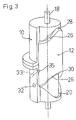
- the rotary piston machine shown in Figures 1 and 2 comprises a cylindrical housing 10 and a formed in the form of a tubular section annular piston 12, which in an annular cavity 14 of the cylindrical Housing 10 is rotatably guided and axially displaceable.
- the piston is via a radial bottom, which is indicated by dashed lines in Figure 1 and designated 16 or non-rotatably via radial spokes with a shaft 18, but axially on the shaft 18 slidably connected, which passes through the housing 10.
- Such an axial displacement enabling rotationally fixed connection can be effected for example via a spline, as shown in Figure 4.
- the annular space 14 has an annular end surface 20 which may have a rectilinear or curved cross-section and which extends in a wave-like manner in the circumferential direction with shaft amplitude directed parallel to the axis.
- the wavy line is approximately sinusoidal and, in the illustrated example, has two peaks or peaks 22 and two wave troughs or minima 24.
- the end face 20 of the annular space 14 facing end or end surface 26 of the annular piston 12 is also formed wave-shaped, as can be seen in Figure 1.
- This end face also has two maxima or wave peaks 28 and two wave troughs 30 (FIGS. 5 to 10).
- this wavy line is designed so that the measured in the circumferential direction half-width of a wave crest, i. the width of the wave crest in the axial center between a wave minimum and a wave maximum is less than the half width of a wave trough.
- the arrangement could also be reversed in that the end face 26 of the ring piston is sinusoidal and the end face 20 of the annulus 14 has narrower peaks and wider troughs.
- one of the inlet and outlet channels 32 can also be seen in the housing 10, which terminates at the inner boundary wall 15 of the annular space 14 and serves for supplying or discharging a working fluid to the annular space 14, as shown in FIGS. 5 to 16 will be explained in more detail.
- the piston 12 is tensioned by a coaxial with the shaft 18 arranged helical spring 34 against the end surface 20 of the annular space 14.
- a plate spring can be used, which can also serve to connect the piston rotation with the shaft. With the diaphragm spring, the axial length is shortened.
- the arrangement of the end surfaces 20 of the annular spaces 14 is selected so that the maxima and minima of the two end surfaces 20 are each on a common generatrix of the cylindrical annular spaces 14, as shown in FIGS. 5 to 16.
- the end faces 26 of the double piston 12 are shaped so that the maximum or crest 28 of one end face with a minimum or the trough 30 of the opposite end face is common to a generatrix of the cylindrical ring piston 12.
- 33 designates a guide groove formed in the radially outer wall of the annular space 14 into which a pin 35 fastened to the piston 12 engages.
- the guide groove follows in the circumferential direction of the waveform of the end surface 20 and thus controls the translational movement of the piston 12, without the end faces 20 and 26 touch. This solution is only optional.
- Figure 4a shows yet another way to reduce the sliding friction between the end surfaces 20 and 26 and thus the wear of these surfaces.
- a roller 37 is rotatably mounted so that it can roll on the end surface 20 of the annular space 14.
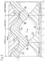
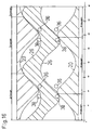
- FIGS. 5 to 10 relate to a rotary piston engine operated as a motor of the type described in FIGS. 3 and 4, the functional explanations of which also apply to the machine according to FIGS. 1 and 2.
- an inlet opening 36 and an outlet opening 38 are each provided on a circumference of 360 ° in such a way that relative to the pointing in the direction of arrow A circumferential direction of the piston 12, the outlet opening 38 in front of a wave crest 22 and the inlet opening 36 to the wave crest 22 is located.
- the shape of the inlet opening 36 and the outlet opening 38 is usually not circular in practice but is depending on the intended use of Rotary engine and also designed in the manner of the medium flowing through, in order to achieve optimum control of the medium flow.
- FIG. 5 shows the piston 12 at top dead center.
- four separate cavities are formed between the upper end surface 20 of the annular space 14 and the upper end surface 26 of the piston 12.
- the lying between 90 ° and 180 ° cavity contains a maximum compressed mixture at the time of ignition. From the lying between 180 ° and 270 ° cavity, the combustion gases were ejected.
- the outlet opening 38 has been closed.
- the inlet opening 36 is gradually opened, so that in the lying between 270 ° and 360 ° cavity mixture is sucked.
- the combustion space measured in the direction of rotation between 270 ° and 90 ° has reached its maximum extent.
- the outlet opening 38 is open.
- the piston 12 is located at its bottom dead center with respect to the lower end surface 20 and the exhaust of the combustion gases from the combustion chamber begins. In the second lying between 90 ° and 270 ° cavity mixture was sucked, which is now compressed with further rotating piston.
- Figure 6 shows the above indicated operations upon rotation of the piston 12 in the direction of the arrow A relative to the fixed housing 10.
- the upper inlet opening 36 is now open, so that mixture can be sucked.
- the outlet opening 38 is closed.
- the combustion chamber increases with the expanding combustion gases.
- In the lower part of the outlet channel is fully open, so that the fuel gases can be ejected while the inlet port is closed, thus allowing a compression in the specified range.
- Figure 8 shows the position inverse to Figure 5, i. the piston 12 is located with respect to the upper end surface 20 of the annular space 14 in its bottom dead center position and with respect to the lower end surface 20 of the annular space 14 in its upper dead center position.
- the state shown in Figure 5 then again follows the figure 10, in which the piston 12 has performed a revolution relative to the housing and thus the four clocks, namely suction, compression, combustion and expulsion of the engine.
- FIGS. 11 to 16 show the same phases for a rotary piston machine designed as a pump. Since there are only two cycles per stroke, namely suction and discharge, two pairs of inlet port 36 (suction line) and outlet port 38 (pressure line) may be provided. Moreover, the operation of the two piston / annulus assemblies is again offset in the same manner by 180 ° to each other, as has already been described in the engine according to Figures 5 to 10.
Landscapes
- Engineering & Computer Science (AREA)
- Mechanical Engineering (AREA)
- General Engineering & Computer Science (AREA)
- Reciprocating Pumps (AREA)
- Hydraulic Motors (AREA)
- Rotary Pumps (AREA)
- Iron Core Of Rotating Electric Machines (AREA)
- Centrifugal Separators (AREA)
Applications Claiming Priority (3)
| Application Number | Priority Date | Filing Date | Title |
|---|---|---|---|
| DE19953168 | 1999-11-04 | ||
| DE19953168A DE19953168A1 (de) | 1999-11-04 | 1999-11-04 | Drehkolbenmaschine |
| PCT/EP2000/010831 WO2001033047A1 (de) | 1999-11-04 | 2000-11-03 | Drehkolbenmaschine |
Publications (2)
| Publication Number | Publication Date |
|---|---|
| EP1226338A1 EP1226338A1 (de) | 2002-07-31 |
| EP1226338B1 true EP1226338B1 (de) | 2006-02-08 |
Family
ID=7927946
Family Applications (1)
| Application Number | Title | Priority Date | Filing Date |
|---|---|---|---|
| EP00974505A Expired - Lifetime EP1226338B1 (de) | 1999-11-04 | 2000-11-03 | Drehkolbenmaschine |
Country Status (7)
| Country | Link |
|---|---|
| US (1) | US6729862B1 (https=) |
| EP (1) | EP1226338B1 (https=) |
| JP (1) | JP2003514163A (https=) |
| AT (1) | ATE317492T1 (https=) |
| AU (1) | AU1278401A (https=) |
| DE (2) | DE19953168A1 (https=) |
| WO (1) | WO2001033047A1 (https=) |
Families Citing this family (4)
| Publication number | Priority date | Publication date | Assignee | Title |
|---|---|---|---|---|
| DE10156835C1 (de) * | 2001-11-20 | 2003-04-30 | Peter Schnabl | Drehkolbenpumpe |
| DE102004019373B4 (de) * | 2004-04-21 | 2013-04-18 | Peter Schnabl | Drehkolbenmaschine |
| US8336409B2 (en) * | 2008-12-11 | 2012-12-25 | Magnamotor, Llc | Magnetic piston apparatus and method |
| GR20180100001A (el) * | 2018-01-03 | 2019-09-06 | Γεωργιτζικη, Ελπιδα Γεωργιου | Μηχανισμος μετατροπης παλινδρομικης κινησης σε περιστροφικη ή αντιστροφα και εφαρμογες του μηχανισμου |
Family Cites Families (11)
| Publication number | Priority date | Publication date | Assignee | Title |
|---|---|---|---|---|
| US1430602A (en) * | 1921-04-29 | 1922-10-03 | Sykora Rudolf | Rotary pump |
| US2517279A (en) * | 1944-04-06 | 1950-08-01 | Benzler Bengt Lennart | Control device for rotary reciprocating engines |
| US3667876A (en) * | 1970-12-21 | 1972-06-06 | Michael David Boyd | Rotary fluid flow machines |
| DE2733574A1 (de) * | 1977-07-26 | 1979-02-08 | Hans Frank | Drehkolbenmaschine |
| BR7805823A (pt) * | 1978-09-06 | 1981-10-27 | C Parente | Bomba rotativa de embolo oscilante na direcao axial com controle e inversao de fluxo |
| GB2075122A (en) * | 1980-04-14 | 1981-11-11 | Jayasooriya L | Rotary positive-displacement fluid-machines |
| GB8922993D0 (en) * | 1989-10-12 | 1989-11-29 | Richards Kevin | Pump or motor |
| ATE146849T1 (de) * | 1991-08-06 | 1997-01-15 | William A Goodman | Rotationspendelkolbenmaschine |
| CA2215219C (en) * | 1996-11-19 | 2000-07-04 | Yukio Kajino | Disc-type rotary engine |
| JP4056600B2 (ja) * | 1996-11-19 | 2008-03-05 | 幸男 梶野 | 円盤型回転エンジン |
| IT1288494B1 (it) | 1996-11-20 | 1998-09-22 | Sasib Spa | Metodo e dispositivo per il controllo senza contatto diretto delle teste delle sigarette, o simili. |
-
1999
- 1999-11-04 DE DE19953168A patent/DE19953168A1/de not_active Withdrawn
-
2000
- 2000-11-03 WO PCT/EP2000/010831 patent/WO2001033047A1/de not_active Ceased
- 2000-11-03 AT AT00974505T patent/ATE317492T1/de not_active IP Right Cessation
- 2000-11-03 US US10/129,343 patent/US6729862B1/en not_active Expired - Fee Related
- 2000-11-03 DE DE50012205T patent/DE50012205D1/de not_active Expired - Lifetime
- 2000-11-03 JP JP2001535711A patent/JP2003514163A/ja active Pending
- 2000-11-03 EP EP00974505A patent/EP1226338B1/de not_active Expired - Lifetime
- 2000-11-03 AU AU12784/01A patent/AU1278401A/en not_active Abandoned
Also Published As
| Publication number | Publication date |
|---|---|
| DE50012205D1 (de) | 2006-04-20 |
| EP1226338A1 (de) | 2002-07-31 |
| AU1278401A (en) | 2001-05-14 |
| DE19953168A1 (de) | 2001-05-10 |
| WO2001033047A1 (de) | 2001-05-10 |
| ATE317492T1 (de) | 2006-02-15 |
| JP2003514163A (ja) | 2003-04-15 |
| US6729862B1 (en) | 2004-05-04 |
Similar Documents
| Publication | Publication Date | Title |
|---|---|---|
| DE3444859C2 (https=) | ||
| DE3690061C2 (de) | Rotationskolbenmaschine | |
| DE1553238B2 (de) | Rotationskolbenmaschine | |
| WO1998013583A1 (de) | Schwenkkolbenmaschine | |
| DE3331636C2 (de) | Aggregat bestehend aus einer Hubkolbenmaschine und einem Getriebe | |
| EP1226338B1 (de) | Drehkolbenmaschine | |
| EP0316346B1 (de) | Drehkolbenmaschine | |
| DE1926050A1 (de) | Radialkolbenmaschine,insbesondere Radialkolbenmotor | |
| DE2921311C2 (https=) | ||
| DE69931181T2 (de) | Rotationspumpe | |
| DE2153946C2 (de) | Führungsgetriebe für eine Umlaufkolben-Brennkraftmaschine | |
| DE4224075A1 (de) | Hydraulisches Antriebs- und Bremssystem | |
| DE4326098A1 (de) | Hydrostatische Maschine | |
| EP0561855B1 (de) | Drehkolbenmaschine | |
| DE19520402C2 (de) | Hydraulischer Kreiskolbenmotor | |
| CH430627A (de) | Radialkolbenmaschine | |
| DE1266648B (de) | Drehkolbenmaschine | |
| DE2333486A1 (de) | Kolbenpumpe oder motor mit einem umlaufenden zylinder | |
| DE1528983C3 (de) | Steuerdrehschiebereinrichtung für eine Rotationskolbenmaschine | |
| DE3508408A1 (de) | Rotationskolbenmaschine | |
| AT219623B (de) | Kraft- oder Arbeitsmaschine mit mindestens einem in einem ringförmigen Zylinder kreisenden Drehkolben | |
| DE1927954A1 (de) | Rotationspumpe oder -motor fuer fluessiges oder gasfoermiges Medium | |
| EP1984600A1 (de) | Einstellbarer segmentverdränger | |
| DE3623490A1 (de) | Abdichtvorrichtung fuer eine drehkolbenmaschine | |
| DE2511221A1 (de) | Druckmittelmotor |
Legal Events
| Date | Code | Title | Description |
|---|---|---|---|
| PUAI | Public reference made under article 153(3) epc to a published international application that has entered the european phase |
Free format text: ORIGINAL CODE: 0009012 |
|
| 17P | Request for examination filed |
Effective date: 20020430 |
|
| AK | Designated contracting states |
Kind code of ref document: A1 Designated state(s): AT BE CH CY DE DK ES FI FR GB GR IE IT LI LU MC NL PT SE TR |
|
| AX | Request for extension of the european patent |
Free format text: AL;LT;LV;MK;RO;SI |
|
| GRAP | Despatch of communication of intention to grant a patent |
Free format text: ORIGINAL CODE: EPIDOSNIGR1 |
|
| GRAS | Grant fee paid |
Free format text: ORIGINAL CODE: EPIDOSNIGR3 |
|
| GRAA | (expected) grant |
Free format text: ORIGINAL CODE: 0009210 |
|
| AK | Designated contracting states |
Kind code of ref document: B1 Designated state(s): AT BE CH CY DE DK ES FI FR GB GR IE IT LI LU MC NL PT SE TR |
|
| PG25 | Lapsed in a contracting state [announced via postgrant information from national office to epo] |
Ref country code: IT Free format text: LAPSE BECAUSE OF FAILURE TO SUBMIT A TRANSLATION OF THE DESCRIPTION OR TO PAY THE FEE WITHIN THE PRESCRIBED TIME-LIMIT;WARNING: LAPSES OF ITALIAN PATENTS WITH EFFECTIVE DATE BEFORE 2007 MAY HAVE OCCURRED AT ANY TIME BEFORE 2007. THE CORRECT EFFECTIVE DATE MAY BE DIFFERENT FROM THE ONE RECORDED. Effective date: 20060208 Ref country code: NL Free format text: LAPSE BECAUSE OF FAILURE TO SUBMIT A TRANSLATION OF THE DESCRIPTION OR TO PAY THE FEE WITHIN THE PRESCRIBED TIME-LIMIT Effective date: 20060208 Ref country code: FI Free format text: LAPSE BECAUSE OF FAILURE TO SUBMIT A TRANSLATION OF THE DESCRIPTION OR TO PAY THE FEE WITHIN THE PRESCRIBED TIME-LIMIT Effective date: 20060208 Ref country code: GB Free format text: LAPSE BECAUSE OF FAILURE TO SUBMIT A TRANSLATION OF THE DESCRIPTION OR TO PAY THE FEE WITHIN THE PRESCRIBED TIME-LIMIT Effective date: 20060208 Ref country code: IE Free format text: LAPSE BECAUSE OF FAILURE TO SUBMIT A TRANSLATION OF THE DESCRIPTION OR TO PAY THE FEE WITHIN THE PRESCRIBED TIME-LIMIT Effective date: 20060208 |
|
| REG | Reference to a national code |
Ref country code: GB Ref legal event code: FG4D Free format text: NOT ENGLISH |
|
| REG | Reference to a national code |
Ref country code: CH Ref legal event code: EP |
|
| REG | Reference to a national code |
Ref country code: IE Ref legal event code: FG4D Free format text: LANGUAGE OF EP DOCUMENT: GERMAN |
|
| REF | Corresponds to: |
Ref document number: 50012205 Country of ref document: DE Date of ref document: 20060420 Kind code of ref document: P |
|
| PG25 | Lapsed in a contracting state [announced via postgrant information from national office to epo] |
Ref country code: SE Free format text: LAPSE BECAUSE OF FAILURE TO SUBMIT A TRANSLATION OF THE DESCRIPTION OR TO PAY THE FEE WITHIN THE PRESCRIBED TIME-LIMIT Effective date: 20060508 Ref country code: DK Free format text: LAPSE BECAUSE OF FAILURE TO SUBMIT A TRANSLATION OF THE DESCRIPTION OR TO PAY THE FEE WITHIN THE PRESCRIBED TIME-LIMIT Effective date: 20060508 |
|
| PG25 | Lapsed in a contracting state [announced via postgrant information from national office to epo] |
Ref country code: ES Free format text: LAPSE BECAUSE OF FAILURE TO SUBMIT A TRANSLATION OF THE DESCRIPTION OR TO PAY THE FEE WITHIN THE PRESCRIBED TIME-LIMIT Effective date: 20060519 |
|
| NLV1 | Nl: lapsed or annulled due to failure to fulfill the requirements of art. 29p and 29m of the patents act | ||
| PG25 | Lapsed in a contracting state [announced via postgrant information from national office to epo] |
Ref country code: PT Free format text: LAPSE BECAUSE OF FAILURE TO SUBMIT A TRANSLATION OF THE DESCRIPTION OR TO PAY THE FEE WITHIN THE PRESCRIBED TIME-LIMIT Effective date: 20060710 |
|
| GBV | Gb: ep patent (uk) treated as always having been void in accordance with gb section 77(7)/1977 [no translation filed] |
Effective date: 20060208 |
|
| REG | Reference to a national code |
Ref country code: IE Ref legal event code: FD4D |
|
| PG25 | Lapsed in a contracting state [announced via postgrant information from national office to epo] |
Ref country code: CH Free format text: LAPSE BECAUSE OF NON-PAYMENT OF DUE FEES Effective date: 20061130 Ref country code: BE Free format text: LAPSE BECAUSE OF NON-PAYMENT OF DUE FEES Effective date: 20061130 Ref country code: LI Free format text: LAPSE BECAUSE OF NON-PAYMENT OF DUE FEES Effective date: 20061130 Ref country code: MC Free format text: LAPSE BECAUSE OF NON-PAYMENT OF DUE FEES Effective date: 20061130 |
|
| PLBE | No opposition filed within time limit |
Free format text: ORIGINAL CODE: 0009261 |
|
| STAA | Information on the status of an ep patent application or granted ep patent |
Free format text: STATUS: NO OPPOSITION FILED WITHIN TIME LIMIT |
|
| 26N | No opposition filed |
Effective date: 20061109 |
|
| EN | Fr: translation not filed | ||
| REG | Reference to a national code |
Ref country code: CH Ref legal event code: PL |
|
| BERE | Be: lapsed |
Owner name: SCHNABL, PETER Effective date: 20061130 |
|
| PG25 | Lapsed in a contracting state [announced via postgrant information from national office to epo] |
Ref country code: AT Free format text: LAPSE BECAUSE OF NON-PAYMENT OF DUE FEES Effective date: 20061103 |
|
| PG25 | Lapsed in a contracting state [announced via postgrant information from national office to epo] |
Ref country code: GR Free format text: LAPSE BECAUSE OF FAILURE TO SUBMIT A TRANSLATION OF THE DESCRIPTION OR TO PAY THE FEE WITHIN THE PRESCRIBED TIME-LIMIT Effective date: 20060509 Ref country code: FR Free format text: LAPSE BECAUSE OF FAILURE TO SUBMIT A TRANSLATION OF THE DESCRIPTION OR TO PAY THE FEE WITHIN THE PRESCRIBED TIME-LIMIT Effective date: 20070330 |
|
| PG25 | Lapsed in a contracting state [announced via postgrant information from national office to epo] |
Ref country code: TR Free format text: LAPSE BECAUSE OF FAILURE TO SUBMIT A TRANSLATION OF THE DESCRIPTION OR TO PAY THE FEE WITHIN THE PRESCRIBED TIME-LIMIT Effective date: 20060208 Ref country code: LU Free format text: LAPSE BECAUSE OF NON-PAYMENT OF DUE FEES Effective date: 20061103 |
|
| PG25 | Lapsed in a contracting state [announced via postgrant information from national office to epo] |
Ref country code: FR Free format text: LAPSE BECAUSE OF FAILURE TO SUBMIT A TRANSLATION OF THE DESCRIPTION OR TO PAY THE FEE WITHIN THE PRESCRIBED TIME-LIMIT Effective date: 20060208 Ref country code: CY Free format text: LAPSE BECAUSE OF FAILURE TO SUBMIT A TRANSLATION OF THE DESCRIPTION OR TO PAY THE FEE WITHIN THE PRESCRIBED TIME-LIMIT Effective date: 20060208 |
|
| PGFP | Annual fee paid to national office [announced via postgrant information from national office to epo] |
Ref country code: DE Payment date: 20101230 Year of fee payment: 11 |
|
| REG | Reference to a national code |
Ref country code: DE Ref legal event code: R119 Ref document number: 50012205 Country of ref document: DE Effective date: 20120601 |
|
| PG25 | Lapsed in a contracting state [announced via postgrant information from national office to epo] |
Ref country code: DE Free format text: LAPSE BECAUSE OF NON-PAYMENT OF DUE FEES Effective date: 20120601 |