EP1226094B1 - Einrichtung für die elektrolyse - Google Patents
Einrichtung für die elektrolyse Download PDFInfo
- Publication number
- EP1226094B1 EP1226094B1 EP00953572A EP00953572A EP1226094B1 EP 1226094 B1 EP1226094 B1 EP 1226094B1 EP 00953572 A EP00953572 A EP 00953572A EP 00953572 A EP00953572 A EP 00953572A EP 1226094 B1 EP1226094 B1 EP 1226094B1
- Authority
- EP
- European Patent Office
- Prior art keywords
- water
- supply system
- generator
- water supply
- electrodes
- Prior art date
- Legal status (The legal status is an assumption and is not a legal conclusion. Google has not performed a legal analysis and makes no representation as to the accuracy of the status listed.)
- Expired - Lifetime
Links
Images
Classifications
-
- C—CHEMISTRY; METALLURGY
- C25—ELECTROLYTIC OR ELECTROPHORETIC PROCESSES; APPARATUS THEREFOR
- C25B—ELECTROLYTIC OR ELECTROPHORETIC PROCESSES FOR THE PRODUCTION OF COMPOUNDS OR NON-METALS; APPARATUS THEREFOR
- C25B15/00—Operating or servicing cells
-
- C—CHEMISTRY; METALLURGY
- C02—TREATMENT OF WATER, WASTE WATER, SEWAGE, OR SLUDGE
- C02F—TREATMENT OF WATER, WASTE WATER, SEWAGE, OR SLUDGE
- C02F1/00—Treatment of water, waste water, or sewage
- C02F1/46—Treatment of water, waste water, or sewage by electrochemical methods
- C02F1/461—Treatment of water, waste water, or sewage by electrochemical methods by electrolysis
- C02F1/46104—Devices therefor; Their operating or servicing
-
- C—CHEMISTRY; METALLURGY
- C02—TREATMENT OF WATER, WASTE WATER, SEWAGE, OR SLUDGE
- C02F—TREATMENT OF WATER, WASTE WATER, SEWAGE, OR SLUDGE
- C02F1/00—Treatment of water, waste water, or sewage
- C02F1/46—Treatment of water, waste water, or sewage by electrochemical methods
- C02F1/461—Treatment of water, waste water, or sewage by electrochemical methods by electrolysis
- C02F1/467—Treatment of water, waste water, or sewage by electrochemical methods by electrolysis by electrochemical disinfection; by electrooxydation or by electroreduction
- C02F1/4672—Treatment of water, waste water, or sewage by electrochemical methods by electrolysis by electrochemical disinfection; by electrooxydation or by electroreduction by electrooxydation
- C02F1/4674—Treatment of water, waste water, or sewage by electrochemical methods by electrolysis by electrochemical disinfection; by electrooxydation or by electroreduction by electrooxydation with halogen or compound of halogens, e.g. chlorine, bromine
-
- C—CHEMISTRY; METALLURGY
- C02—TREATMENT OF WATER, WASTE WATER, SEWAGE, OR SLUDGE
- C02F—TREATMENT OF WATER, WASTE WATER, SEWAGE, OR SLUDGE
- C02F2201/00—Apparatus for treatment of water, waste water or sewage
- C02F2201/46—Apparatus for electrochemical processes
- C02F2201/461—Electrolysis apparatus
- C02F2201/46105—Details relating to the electrolytic devices
- C02F2201/4616—Power supply
- C02F2201/46165—Special power supply, e.g. solar energy or batteries
-
- C—CHEMISTRY; METALLURGY
- C02—TREATMENT OF WATER, WASTE WATER, SEWAGE, OR SLUDGE
- C02F—TREATMENT OF WATER, WASTE WATER, SEWAGE, OR SLUDGE
- C02F2303/00—Specific treatment goals
- C02F2303/04—Disinfection
Definitions
- the present invention relates to an electrolytic device for a water supply system, comprising an electrolytic cell which is provided with electrodes over which a voltage difference is applied.
- the invention further relates to a method for disinfecting a water supply system by electrolysis.
- the chlorine formed at the anode may, depending on the pH, also be present as hypochlorous acid (HClO) or as a hypochlorite (ClO - ). Dissolved chlorine, hypochlorous acid and hypochlorite are called “free chlorine” or "free active chlorine".
- HClO hypochlorous acid
- ClO - hypochlorite
- Dissolved chlorine, hypochlorous acid and hypochlorite are called "free chlorine” or "free active chlorine”.
- tap water having a pH of about 7 to 8 and containing a small concentration of NaCl, sodium hypochlorite will be formed.
- the quantity of free chlorine to be formed will depend on the wanted concentration and the quantity of water to be treated.
- Common equipment for disinfecting water consists of an electrolytic cell, a rectifier to convert mains voltage into direct current and a control to adapt the electric current to be supplied to the electrodes to the water flow rate.
- US 5,228,964 discloses a chlorinating apparatus for use with a saltwater swimming pool having a pump for circulating the water between the swimmingpool and a filter, which apparatus comprises electricity generating means, driven by the flow of water produced by the pump, for providing an electrical output and electrode means connected with the electrical output of the electricity generating means for generating chlorine from the salt water.
- the housing of the apparatus is connected with the outlet of the pipe returning the water from the pump/filter to the pool.
- the apparatus is placed in a chamber containing the leafbasket of a conventional swimming pool, the bottom of the chamber being connected through a pipe with the pump/filter.
- the electricity generating means comprises a generator, such as a sealed dynamo, within the housing of the apparatus having a rotatable shaft on which is mounted an impeller.
- the electricity generating means may generate either AC or DC voltage.
- the electrode means comprises a plurality of spaced mesh electrodes, such as alloy-coated titanium electrodes.
- US patent 4,272,686 discloses an electrical power plant for generating electrical energy from the energy of a fluid flowing within a pipeline, comprising a turbine having a plurality of vanes, a flywheel for driving an electrical generator, a shaft connecting said turbine and said flywheel, a housing having a first chamber housing the turbine, a second chamber housing the flywheel and inlet and outlet openings.
- the plant may be provided with a second, smaller generator connected with an ozone generator placed in the second chamber for producing ozone to eliminate bacteria and to reduce odours within the second chamber.
- JP-08103777A relates to a steriliser comprising a device connected to the water tap of service water and equipped with a turbine which is driven by the water flow from the nozzle of the service water tap, a direct current generator driven by the turbine, an ozone generator driven by the electric current produced by the generator and an ozone injector which injects ozone into the service water.
- an electrolytic device for disinfecting water in a water supply system comprising in one housing an electrolytic cell which is provided with electrodes over which a voltage difference is applied, which electrodes contact the water in the water supply system, a generator for supplying the voltage difference for the electrolytic cell, which generator is driven by the water in the water supply system, a water inlet opening to be connected to the water supply system, characterised in that the device further comprises a water outlet opening to be connected to the water supply system, and a variable resistance for adapting the voltage to be supplied to the electrodes to the properties of the water in the water supply system, wherein the electric current supplied by the generator is substantially proportional to the quantity of water flowing past the generator.
- the invention further relates to a method for disinfecting water in a water supply system using the above described electrolytic device.
- water supply system means each pipe through which water is guided or in which water is present.
- Said pipe may for instance be a hot water pipe in a residence, but also a supply pipe for fresh or recycled water in a swimming pool.
- the generator In case the generator is of the type which supplies an electric current which is proportional to the quantity of water flowing past it, the generator, when the speed of flow increases and more water has to be disinfected, will supply more power so that more free chlorine is formed.
- a suitable type of generator is a turbine, particularly a DC turbine.
- the device can be adjusted to the conductance of the water.
- variations of the water composition in water supply systems are usually of a minor nature, it will in general not be necessary to adapt the adjustment for a long time.
- the device of the invention therefore provides in its own need for power and is self adjusting.
- a very simple apparatus that can be built in against low costs, is obtained when the electrolytic cell and the generator, or at least its driving part, are accommodated in one housing.
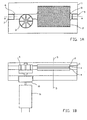
- FIG. 1A a cross-section of a device according to the invention, in which the electrolytic cell and the driving part of the turbine are accommodated in one housing, is shown schematically.
- Figure 1 B schematically shows a cross-section of the device along line A-A in figure 1A.
- 1 refers to a housing
- 2 refers to an electrolytic cell
- 3 refers to a blade wheel of a turbine.
- a channel 6, in which the blade wheel 3 is placed connects the electrolytic cell 2 with a water inlet opening 7 to be connected to the water supply system and a channel 8 connects the electrolytic cell 2 to a water outlet opening 9 to be connected to the water supply system.
- the blade wheel 3 is connected to a turbine 11 via a magnet coupling 10.
- Such a system can be placed in all kinds of water supply systems, taking the possible water flow rates into account in order to determine the maximum capacity of the apparatus.
- the device of the invention disinfects the water not only directly through anodic oxidation, but free chlorine is also produced so that a disinfecting action remains present.
- the apparatus need not be installed directly near the location of use, but it may also be placed in the main supply system.
- a suitable electrode material is a stretch metal of titanium provided with a ruthenium or platinum coating.
- the stretch metal lets water through well, so that the electrodes can be placed transverse to the flow direction, optionally in the shape of a harmonica, so that the water contacts the electrodes several times. Any other commonly used suitable electrode material and any other commonly used suitable electrode shape, however, can also be used.
- a spacer for instance made of a porous synthetic material such as PVDF gauze, can be arranged between the electrodes.
- the concentration of free chlorine used for disinfecting water is usually between 0.1 and 1 ppm. At a low concentration of salt the quantity of free chlorine produced is approximately 1 g/Ah. At a water flow rate of 1000 l/h approximately 0.1 g chlorine/h will be necessary for obtaining a concentration of free chlorine of approximately 0.1 ppm, which corresponds to a current of approximately 0.1 A (at a voltage of about 3 V over the electrodes).
- a voltage of approximately 3 volt DC is needed for a current density of 0.5 A/dm 2 .
- the water to be treated contains sodium chloride and during electrolysis free chlorine will be created. However it has appeared that when the conductance is sufficient, also in the absence of chlorine active compounds are formed which can ensure disinfection.
Claims (8)
- Elektrolysevorrichtung zum Desinfektieren von Wasser in einem Wasserleitungssystem, umfassend in einem Gehäuse:dadurch gekennzeichnet, daß die Vorrichtung weiter umfaßteine Elektrolysezelle, mit Elektroden versehen, über welche Elektroden eine Spannungsdifferenz angelegt wird, welche Elektroden mit dem Wasser in dem Wasserleitungssystem Kontakt haben,einen Generator zum Liefern der Spannungsdifferenz für die Elektrolysezelle, welcher Generator durch das Wasser in dem Wasserleitungssystem angetrieben wird,eine Wassereinlaßöffnung, die mit dem Wasserleitungssystem verbunden werden soll,
eine Wasserauslaßöffnung, die mit dem Wasserleitungssystem verbunden werden soll, und einen
veränderlichen Widerstand um die an die Elektroden zu liefernde Spannung an die Eigenschaften des Wassers in dem Wasserleitungssystem anzupassen, wobei der durch den Generator gelieferte elektrische Strom hauptsächlich proportional zu der entlang des Generators fließenden Wassermenge ist. - Elektrolysevorrichtung nach Anspruch 1, wobei der Generator eine Turbine ist.
- Elektrolysevorrichtung nach Anspruch 2, wobei die Turbine eine Gleichstromturbine ist.
- Elektrolysesystem nach einem der vorhergehenden Ansprüche, welcher mit Mitteln zum periodisch Umpolarisieren der Elektroden versehen ist.
- Verfahren zum Desinfizieren von Wasser in einem Wasserleitungssystem, umfassend das Führen von Wasser durch eine Elektrolysevorrichtung umfassend in einem Gehäuse eine Elektrolysezelle mit Elektroden versehen, über welche Elektroden eine Spannungsdifferenz angelegt wird, welche Elektroden mit dem Wasser in dem Wasserleitungssystem Kontakt haben, einen Generator zum Liefern der Spannungsdifferenz für die Elektrolysezelle, welcher Generator durch das Wasser in dem Wasserleitungssystem angetrieben wird,
eine Wassereinlaßöffnung, die mit dem Wasserleitungssystem verbunden werden soll,
dadurch gekennzeichnet, daß die Vorrichtung weiter umfaßt
eine Wasseraustaßöffnung, die mit dem Wasserleitungssystem verbunden werden soll, und einen
veränderlichen Widerstand um die an die Elektroden zu liefernde Spannung an die Eigenschaften des Wassers in dem Wasserleitungssystem anzupassen, wobei der durch den Generator gelieferte elektrische Strom hauptsächlich proportional zu der entlang des Generators fließenden Wassermenge ist. - Verfahren nach Anspruch 5, wobei der Generator eine Turbine ist.
- Verfahren nach Anspruch 6, wobei die Turbine eine Gleichstromturbine ist.
- Verfahren nach einem der Ansprüche 5-7, wobei die Elektrolysevorrichtung mit Mitteln zum periodisch Umpolarisieren der Elektroden versehen ist.
Applications Claiming Priority (3)
| Application Number | Priority Date | Filing Date | Title |
|---|---|---|---|
| NL1012794A NL1012794C2 (nl) | 1999-08-09 | 1999-08-09 | Elektrolyse-inrichting en werkwijze voor het desinfecteren van water. |
| NL1012794 | 1999-08-09 | ||
| PCT/NL2000/000527 WO2001017908A1 (en) | 1999-08-09 | 2000-07-25 | Device for electrolysis |
Publications (2)
| Publication Number | Publication Date |
|---|---|
| EP1226094A1 EP1226094A1 (de) | 2002-07-31 |
| EP1226094B1 true EP1226094B1 (de) | 2003-11-26 |
Family
ID=19769712
Family Applications (1)
| Application Number | Title | Priority Date | Filing Date |
|---|---|---|---|
| EP00953572A Expired - Lifetime EP1226094B1 (de) | 1999-08-09 | 2000-07-25 | Einrichtung für die elektrolyse |
Country Status (8)
| Country | Link |
|---|---|
| EP (1) | EP1226094B1 (de) |
| AT (1) | ATE255068T1 (de) |
| AU (1) | AU6599700A (de) |
| DE (1) | DE60006847T2 (de) |
| ES (1) | ES2211582T3 (de) |
| NL (1) | NL1012794C2 (de) |
| PT (1) | PT1226094E (de) |
| WO (1) | WO2001017908A1 (de) |
Cited By (1)
| Publication number | Priority date | Publication date | Assignee | Title |
|---|---|---|---|---|
| CN101423271B (zh) * | 2007-10-29 | 2013-06-05 | 江口日出雄 | 水杀菌装置及水杀菌方法 |
Families Citing this family (3)
| Publication number | Priority date | Publication date | Assignee | Title |
|---|---|---|---|---|
| NL1019698C2 (nl) | 2002-01-04 | 2003-07-09 | Johannes Petrus Paulus Tholen | Elektrolyse-inrichting en werkwijze voor het desinfecteren van water in een waterleidingsysteem door middel van de generatie van actief chloor. |
| DE102012112560B3 (de) * | 2012-12-18 | 2014-05-15 | Kumatec Sondermaschinenbau & Kunststoffverarbeitung Gmbh | Flügelradpumpe für einen Elektrolyseur |
| BR112017002788A2 (pt) | 2014-08-11 | 2018-01-30 | Formarum Inc | sistema e método de tratamento de água |
Family Cites Families (6)
| Publication number | Priority date | Publication date | Assignee | Title |
|---|---|---|---|---|
| FR2196201A1 (en) * | 1972-08-21 | 1974-03-15 | Saint Gobain Techn Nouvelles | Decarbonising electrolysis electrodes - by periodic inversion of polarities in the electrolytic appts |
| DE2626569C2 (de) * | 1976-06-14 | 1986-01-16 | Sachs Systemtechnik Gmbh, 8720 Schweinfurt | Vorrichtung zur Regelung und Überwachung der Stromversorgung eines Versorgungssystems für entkeimte Flüssigkeiten |
| US4272686A (en) * | 1980-03-25 | 1981-06-09 | Kunio Suzuki | Apparatus for converting hydraulic energy to electrical energy |
| US5228964A (en) * | 1991-02-07 | 1993-07-20 | Middleby Samuel R | Chlorinating apparatus |
| JPH08103777A (ja) * | 1994-09-30 | 1996-04-23 | Amtex:Kk | 水道水浄化装置 |
| JPH1137036A (ja) * | 1997-07-11 | 1999-02-09 | Yoshiaki Ogawa | 発電動力機 |
-
1999
- 1999-08-09 NL NL1012794A patent/NL1012794C2/nl not_active IP Right Cessation
-
2000
- 2000-07-25 ES ES00953572T patent/ES2211582T3/es not_active Expired - Lifetime
- 2000-07-25 AT AT00953572T patent/ATE255068T1/de not_active IP Right Cessation
- 2000-07-25 AU AU65997/00A patent/AU6599700A/en not_active Abandoned
- 2000-07-25 EP EP00953572A patent/EP1226094B1/de not_active Expired - Lifetime
- 2000-07-25 DE DE60006847T patent/DE60006847T2/de not_active Expired - Lifetime
- 2000-07-25 WO PCT/NL2000/000527 patent/WO2001017908A1/en active IP Right Grant
- 2000-07-25 PT PT00953572T patent/PT1226094E/pt unknown
Cited By (1)
| Publication number | Priority date | Publication date | Assignee | Title |
|---|---|---|---|---|
| CN101423271B (zh) * | 2007-10-29 | 2013-06-05 | 江口日出雄 | 水杀菌装置及水杀菌方法 |
Also Published As
| Publication number | Publication date |
|---|---|
| NL1012794C2 (nl) | 2001-02-12 |
| PT1226094E (pt) | 2004-04-30 |
| ATE255068T1 (de) | 2003-12-15 |
| AU6599700A (en) | 2001-04-10 |
| WO2001017908A1 (en) | 2001-03-15 |
| EP1226094A1 (de) | 2002-07-31 |
| ES2211582T3 (es) | 2004-07-16 |
| DE60006847D1 (de) | 2004-01-08 |
| DE60006847T2 (de) | 2004-11-04 |
Similar Documents
| Publication | Publication Date | Title |
|---|---|---|
| CA2112677C (en) | Electrolytic cell assembly and process for production of bromine | |
| JP3716042B2 (ja) | 酸性水の製造方法及び電解槽 | |
| US7695606B2 (en) | Electrolytic device and method for disinfecting water in a water supply system by means of the generation of active chlorine | |
| KR100634760B1 (ko) | 과전위전극 전해셀을 이용한 살균산화수 제조장치 | |
| EP3759053A1 (de) | Elektrolyseverfahren und -vorrichtung für thermal- und schwimmbäder | |
| EP1226094B1 (de) | Einrichtung für die elektrolyse | |
| JPH0673675B2 (ja) | 電解による次亜塩素酸含有殺菌水の製造方法 | |
| KR20090083796A (ko) | 모듈형 전해셀을 구비한 저용량 차아염소산나트륨 발생장치 | |
| KR100603536B1 (ko) | 메쉬형 전극판을 갖는 전기분해장치 | |
| KR102104510B1 (ko) | 소규모 상수시설용 살균장치 | |
| KR101367779B1 (ko) | 염소소독수 생성장치의 염수 공급구조 | |
| MX2012007677A (es) | Proceso y aparato para desinfectar agua para producir iones de hidroxilos a traves de la hidrolisis de las moleculas de agua. | |
| JPH09206755A (ja) | 電解によるアルカリイオン水と次亜塩素酸殺菌水の生 成方法及び装置 | |
| JP2892121B2 (ja) | 電解による次亜塩素酸含有殺菌水の製造方法 | |
| JP3401294B2 (ja) | 電解水処理方法 | |
| KR200342557Y1 (ko) | 메쉬형 전극판을 갖는 전기분해장치 | |
| JP2003126858A (ja) | 電解水生成方法 | |
| KR200262827Y1 (ko) | 정수기 저수조 내 물의 살균을 위한 전기화학적 장치 | |
| KR20230040433A (ko) | 살균 및 수소공급이 가능한 수전 | |
| JP2023089000A (ja) | 酸化剤濃度の制御のための方法及び装置 | |
| KR20130110773A (ko) | 무가염 소독장치 및 그 제어방법 | |
| JPH07163983A (ja) | 流水形水電解式消毒器 | |
| JPH1133553A (ja) | インライン塩素発生電解装置と該装置を用いた被処理水の電解処理方法 | |
| JPH0751665A (ja) | 水道水の処理装置 | |
| JP2004216380A (ja) | 電解水生成方法 |
Legal Events
| Date | Code | Title | Description |
|---|---|---|---|
| PUAI | Public reference made under article 153(3) epc to a published international application that has entered the european phase |
Free format text: ORIGINAL CODE: 0009012 |
|
| 17P | Request for examination filed |
Effective date: 20020208 |
|
| AK | Designated contracting states |
Kind code of ref document: A1 Designated state(s): AT BE CH CY DE DK ES FI FR GB GR IE IT LI LU MC NL PT SE |
|
| AX | Request for extension of the european patent |
Free format text: AL;LT;LV;MK;RO;SI |
|
| GRAH | Despatch of communication of intention to grant a patent |
Free format text: ORIGINAL CODE: EPIDOS IGRA |
|
| GRAS | Grant fee paid |
Free format text: ORIGINAL CODE: EPIDOSNIGR3 |
|
| GRAA | (expected) grant |
Free format text: ORIGINAL CODE: 0009210 |
|
| AK | Designated contracting states |
Kind code of ref document: B1 Designated state(s): AT BE CH CY DE DK ES FI FR GB GR IE IT LI LU MC NL PT SE |
|
| PG25 | Lapsed in a contracting state [announced via postgrant information from national office to epo] |
Ref country code: FI Free format text: LAPSE BECAUSE OF FAILURE TO SUBMIT A TRANSLATION OF THE DESCRIPTION OR TO PAY THE FEE WITHIN THE PRESCRIBED TIME-LIMIT Effective date: 20031126 Ref country code: CY Free format text: LAPSE BECAUSE OF FAILURE TO SUBMIT A TRANSLATION OF THE DESCRIPTION OR TO PAY THE FEE WITHIN THE PRESCRIBED TIME-LIMIT Effective date: 20031126 Ref country code: AT Free format text: LAPSE BECAUSE OF FAILURE TO SUBMIT A TRANSLATION OF THE DESCRIPTION OR TO PAY THE FEE WITHIN THE PRESCRIBED TIME-LIMIT Effective date: 20031126 |
|
| REG | Reference to a national code |
Ref country code: GB Ref legal event code: FG4D |
|
| REG | Reference to a national code |
Ref country code: CH Ref legal event code: EP |
|
| REF | Corresponds to: |
Ref document number: 60006847 Country of ref document: DE Date of ref document: 20040108 Kind code of ref document: P |
|
| REG | Reference to a national code |
Ref country code: IE Ref legal event code: FG4D |
|
| PG25 | Lapsed in a contracting state [announced via postgrant information from national office to epo] |
Ref country code: DK Free format text: LAPSE BECAUSE OF FAILURE TO SUBMIT A TRANSLATION OF THE DESCRIPTION OR TO PAY THE FEE WITHIN THE PRESCRIBED TIME-LIMIT Effective date: 20040226 Ref country code: SE Free format text: LAPSE BECAUSE OF FAILURE TO SUBMIT A TRANSLATION OF THE DESCRIPTION OR TO PAY THE FEE WITHIN THE PRESCRIBED TIME-LIMIT Effective date: 20040226 |
|
| REG | Reference to a national code |
Ref country code: CH Ref legal event code: NV Representative=s name: E. BLUM & CO. PATENTANWAELTE |
|
| REG | Reference to a national code |
Ref country code: GR Ref legal event code: EP Ref document number: 20040400637 Country of ref document: GR |
|
| REG | Reference to a national code |
Ref country code: PT Ref legal event code: SC4A Free format text: AVAILABILITY OF NATIONAL TRANSLATION Effective date: 20040218 |
|
| LTIE | Lt: invalidation of european patent or patent extension |
Effective date: 20031126 |
|
| REG | Reference to a national code |
Ref country code: ES Ref legal event code: FG2A Ref document number: 2211582 Country of ref document: ES Kind code of ref document: T3 |
|
| PG25 | Lapsed in a contracting state [announced via postgrant information from national office to epo] |
Ref country code: LU Free format text: LAPSE BECAUSE OF NON-PAYMENT OF DUE FEES Effective date: 20040725 |
|
| PG25 | Lapsed in a contracting state [announced via postgrant information from national office to epo] |
Ref country code: IE Free format text: LAPSE BECAUSE OF NON-PAYMENT OF DUE FEES Effective date: 20040726 |
|
| PG25 | Lapsed in a contracting state [announced via postgrant information from national office to epo] |
Ref country code: MC Free format text: LAPSE BECAUSE OF NON-PAYMENT OF DUE FEES Effective date: 20040731 |
|
| ET | Fr: translation filed | ||
| PLBE | No opposition filed within time limit |
Free format text: ORIGINAL CODE: 0009261 |
|
| STAA | Information on the status of an ep patent application or granted ep patent |
Free format text: STATUS: NO OPPOSITION FILED WITHIN TIME LIMIT |
|
| 26N | No opposition filed |
Effective date: 20040827 |
|
| REG | Reference to a national code |
Ref country code: IE Ref legal event code: MM4A |
|
| REG | Reference to a national code |
Ref country code: CH Ref legal event code: PFA Owner name: THOLEN, JOHANNES, PETRUS, PAULUS Free format text: THOLEN, JOHANNES, PETRUS, PAULUS#GRAAF WICHMANLAAN 19#1405 GX BUSSUM (NL) -TRANSFER TO- THOLEN, JOHANNES, PETRUS, PAULUS#GRAAF WICHMANLAAN 19#1405 GX BUSSUM (NL) |
|
| PGFP | Annual fee paid to national office [announced via postgrant information from national office to epo] |
Ref country code: ES Payment date: 20100716 Year of fee payment: 11 Ref country code: CH Payment date: 20100709 Year of fee payment: 11 |
|
| PGFP | Annual fee paid to national office [announced via postgrant information from national office to epo] |
Ref country code: FR Payment date: 20100805 Year of fee payment: 11 Ref country code: IT Payment date: 20100717 Year of fee payment: 11 Ref country code: DE Payment date: 20100722 Year of fee payment: 11 |
|
| PGFP | Annual fee paid to national office [announced via postgrant information from national office to epo] |
Ref country code: GR Payment date: 20100630 Year of fee payment: 11 Ref country code: GB Payment date: 20100721 Year of fee payment: 11 |
|
| PGFP | Annual fee paid to national office [announced via postgrant information from national office to epo] |
Ref country code: PT Payment date: 20100701 Year of fee payment: 11 |
|
| PGFP | Annual fee paid to national office [announced via postgrant information from national office to epo] |
Ref country code: BE Payment date: 20100722 Year of fee payment: 11 |
|
| BERE | Be: lapsed |
Owner name: *THOLEN JOHANNES PETRUS PAULUS Effective date: 20110731 |
|
| REG | Reference to a national code |
Ref country code: PT Ref legal event code: MM4A Free format text: LAPSE DUE TO NON-PAYMENT OF FEES Effective date: 20120125 |
|
| REG | Reference to a national code |
Ref country code: CH Ref legal event code: PL |
|
| GBPC | Gb: european patent ceased through non-payment of renewal fee |
Effective date: 20110725 |
|
| REG | Reference to a national code |
Ref country code: GR Ref legal event code: ML Ref document number: 20040400637 Country of ref document: GR Effective date: 20120202 |
|
| REG | Reference to a national code |
Ref country code: FR Ref legal event code: ST Effective date: 20120330 |
|
| PG25 | Lapsed in a contracting state [announced via postgrant information from national office to epo] |
Ref country code: CH Free format text: LAPSE BECAUSE OF NON-PAYMENT OF DUE FEES Effective date: 20110731 Ref country code: BE Free format text: LAPSE BECAUSE OF NON-PAYMENT OF DUE FEES Effective date: 20110731 Ref country code: LI Free format text: LAPSE BECAUSE OF NON-PAYMENT OF DUE FEES Effective date: 20110731 Ref country code: DE Free format text: LAPSE BECAUSE OF NON-PAYMENT OF DUE FEES Effective date: 20120201 Ref country code: FR Free format text: LAPSE BECAUSE OF NON-PAYMENT OF DUE FEES Effective date: 20110801 |
|
| REG | Reference to a national code |
Ref country code: DE Ref legal event code: R119 Ref document number: 60006847 Country of ref document: DE Effective date: 20120201 |
|
| PG25 | Lapsed in a contracting state [announced via postgrant information from national office to epo] |
Ref country code: PT Free format text: LAPSE BECAUSE OF NON-PAYMENT OF DUE FEES Effective date: 20120125 Ref country code: GR Free format text: LAPSE BECAUSE OF NON-PAYMENT OF DUE FEES Effective date: 20120202 Ref country code: IT Free format text: LAPSE BECAUSE OF NON-PAYMENT OF DUE FEES Effective date: 20110725 |
|
| PG25 | Lapsed in a contracting state [announced via postgrant information from national office to epo] |
Ref country code: GB Free format text: LAPSE BECAUSE OF NON-PAYMENT OF DUE FEES Effective date: 20110725 |
|
| REG | Reference to a national code |
Ref country code: ES Ref legal event code: FD2A Effective date: 20130821 |
|
| PG25 | Lapsed in a contracting state [announced via postgrant information from national office to epo] |
Ref country code: ES Free format text: LAPSE BECAUSE OF NON-PAYMENT OF DUE FEES Effective date: 20110726 |
|
| PGFP | Annual fee paid to national office [announced via postgrant information from national office to epo] |
Ref country code: NL Payment date: 20160705 Year of fee payment: 17 |
|
| REG | Reference to a national code |
Ref country code: NL Ref legal event code: MM Effective date: 20170801 |
|
| PG25 | Lapsed in a contracting state [announced via postgrant information from national office to epo] |
Ref country code: NL Free format text: LAPSE BECAUSE OF NON-PAYMENT OF DUE FEES Effective date: 20170801 |