EP1225089A2 - Armlehne mit beweglicher Armauflage, insbesondere für Fahrzeuge - Google Patents
Armlehne mit beweglicher Armauflage, insbesondere für Fahrzeuge Download PDFInfo
- Publication number
- EP1225089A2 EP1225089A2 EP02000627A EP02000627A EP1225089A2 EP 1225089 A2 EP1225089 A2 EP 1225089A2 EP 02000627 A EP02000627 A EP 02000627A EP 02000627 A EP02000627 A EP 02000627A EP 1225089 A2 EP1225089 A2 EP 1225089A2
- Authority
- EP
- European Patent Office
- Prior art keywords
- armrest
- guide rods
- guide
- support element
- armrest according
- Prior art date
- Legal status (The legal status is an assumption and is not a legal conclusion. Google has not performed a legal analysis and makes no representation as to the accuracy of the status listed.)
- Granted
Links
- 230000000694 effects Effects 0.000 description 2
- NJPPVKZQTLUDBO-UHFFFAOYSA-N novaluron Chemical compound C1=C(Cl)C(OC(F)(F)C(OC(F)(F)F)F)=CC=C1NC(=O)NC(=O)C1=C(F)C=CC=C1F NJPPVKZQTLUDBO-UHFFFAOYSA-N 0.000 description 2
- 239000011248 coating agent Substances 0.000 description 1
- 238000000576 coating method Methods 0.000 description 1
- 238000004519 manufacturing process Methods 0.000 description 1
- 230000036316 preload Effects 0.000 description 1
- 230000001960 triggered effect Effects 0.000 description 1
Images
Classifications
-
- B—PERFORMING OPERATIONS; TRANSPORTING
- B60—VEHICLES IN GENERAL
- B60N—SEATS SPECIALLY ADAPTED FOR VEHICLES; VEHICLE PASSENGER ACCOMMODATION NOT OTHERWISE PROVIDED FOR
- B60N2/00—Seats specially adapted for vehicles; Arrangement or mounting of seats in vehicles
- B60N2/75—Arm-rests
- B60N2/763—Arm-rests adjustable
- B60N2/773—Longitudinal adjustment
Definitions
- the invention relates to an armrest with a longitudinally movable armrest, the especially between the front seats in the area of the center console of passenger cars can be used.
- an armrest for a seat which is provided on a base device which can be pivoted about a pivot axis which is fixed to the seat.
- the base device In order to adjust the armrest in the longitudinal direction, the base device has a linear guide which consists of a pair of guide rods which are spaced parallel to one another and two bushings which form the bearing point of the armrest.
- the guide rods are guided with a sliding fit tolerance in the bearing point.
- An armrest with a longitudinally adjustable armrest element is described in DE 198 46 030 C1. This covers a slide which is slidably mounted on a base body of the armrest.
- the armrest element is designed to be bendable in at least one partial area, so that when the carriage is moved forward or backward, the armrest element can be extended accordingly.
- the length of the armrest element that is not required moves invisibly under the sled. This solution is very complex and costly to manufacture. In addition, the driver or operator must adjust the slide himself.
- the invention has for its object an armrest with a movable armrest, especially for vehicles, to create a simple and safe Adjustment mechanism for the linear movement distinguishes a small Operating effort required and in the position of use the selected position maintains.
- the guide rods are arranged to be linearly movable in the associated guides and are firmly connected to the support element. This is adapted to the contour of the armrest and connected to the actual armrest as upholstery or the like.
- the guide rods are connected to an adjusting and braking device. When the armrest is relieved, the guide rods can be moved in the longitudinal direction in the guides. The driver or operator can easily move the armrest into the desired position. If he places the arm on the armrest (load condition), a braking effect is automatically triggered and the armrest is locked in the respective position. After a corresponding relief of the armrest, it can then be moved to another position.
- the setting and braking device is designed as follows.
- the guides in which the guide rods are guided in a linearly movable manner are each arranged in a lever.
- the levers are rotatably received in separate bearing blocks on a common base plate and are pressed independently of one another by means of springs against a stop.
- the guide rods mounted in the levers are moved upward by a few mm, so that a corresponding gap or free space is formed between the base plate and the lower end faces of the armrest or the support element connected to it.
- the bearing blocks are arranged symmetrically spaced from one another parallel to the longitudinal axis and each have on their inwardly directed longitudinal side a swivel-type holder with an axis of rotation for receiving the respective lever.
- Each lever has a short downwardly angled section and a section running parallel to the top of the pedestal.
- the axis of rotation is in the bend area between these two sections.
- At the end of the short downwardly angled section of the levers there are two spaced-apart jaws which have a friction surface lying in the vertical plane, which is designed as a brake lining.
- the support element connected to the guide rods, which are guided in the end region of the lever section running parallel to the upper side of the pedestal, has an elongated profile-shaped guide, which in the installed position is located in the longitudinal direction between the two pedestals, while maintaining a sufficient guide play.
- the brake shoes of the lever arms are pressed against the guide profile of the support element and bring about the aforementioned locking of the guide rods.
- the brake shoes are moved back by the spring-loaded levers until they stop on the inside of the pedestals. This removes the braking effect and the armrest attached to the guide rods can be moved in the longitudinal direction again.
- one or more shaped springs are arranged between the base plate and the guide profile. To move the armrest into the position desired by the operator, the operator only has to overcome the preload of these springs with little effort.
- the proposed armrest is characterized by a simple structure and can be manufactured inexpensively. It can be easily and quickly installed at various points in a vehicle, e.g. B on a swiveling armrest bracket between the seats or on the center console in the area of the front seats.
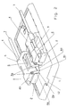
- the armrest consists of a base plate 1, the z. B. is attached to a pivotable armrest support or is firmly connected to the center console in the area of the front seats of a passenger car.
- two identical bearing blocks 2 are spaced parallel to one another on the base plate 1 symmetrically to the longitudinal axis.
- the bearing blocks 2 and the base plate 1 can be designed as a one-piece component.
- the bearing blocks 2 have on the inward-facing long side a swivel bracket 3 with an axis of rotation 3a for receiving a lever 4 each, with a short downwardly bent section 4a and a section 4b running parallel to the upper side of the bearing block 2.
- a spring 5 is arranged in the central region of the holder 3, by means of which the section 4b of the lever 4 is pressed upwards in the direction of the arrow until the section 4a of the lever 4 strikes the inside 2a of the bearing block 2.
- the bent section 4a of the lever 4 has at its end two jaws 4c with a friction surface 4d lying in the vertical plane, which are provided with a suitable coating. The mode of operation of these friction surfaces will be dealt with separately elsewhere.
- the two guide rods 7 movable in the longitudinal axis have two stops (not shown in more detail) for limiting the axial movement.
- the two symmetrically arranged guide rods 7 can be moved in a range of 80 to 90 mm, the adjustment range of the armrest.
- the support element 9 for the actual armrest 10 is attached, for. B. by a known snap lock.
- the support element 9 has an elongated, narrow guide profile 9a in the center, which extends over the entire length of the base plate 1 and, when the support element 9 is in place, is located with a slight play between the jaws 4c of the two levers 4. This guidance of the support element 9 ensures a central position of the support element 9 even when the armrest or armrest is subjected to a lateral load.
- a recess or guide groove 12 for the guide profile 9a of the support element 9 is arranged in order to allow an undisturbed extension movement for this.
- the padded armrest 10 is placed on the support element 9.
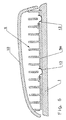
- the linearly movable parts of the armrest are secured by one or more form springs 13, which are secured between the base plate 1 and the guide profile 9a of the support element 9 against undesired movement, for example when the vehicle brakes.
- the form springs 13 are attached to the underside of the guide profile 9a of the support element 9.
- the operator can move the armrest 10 in the longitudinal direction into the position desired by a linear movement of the guide rods 7 guided in both guides 6.
- the springs 5 press the lever sections 4b upwards until Stop of the lever sections 4a on the inside 2a of the bearing blocks 2.
- the jaws 4c of the lever sections 4a release the guide profile 9a of the support elements 9.
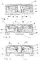
- the support element 9 with the armrest 10 is slightly raised with respect to the base plate 1, for. B. by a height of 3 mm, as shown in Figures 3 to 5.
- the lever sections 4b of the two levers 4 are pressed down against the bias of the springs 5 and at the same time the jaws 4c with their friction surfaces 4d are pressed against the guide profile 9a of the support elements 9 and this locked in its current position. After relieving the pressure on the armrest, the operator can move it lengthways to another position.
Landscapes
- Engineering & Computer Science (AREA)
- Aviation & Aerospace Engineering (AREA)
- Transportation (AREA)
- Mechanical Engineering (AREA)
- Seats For Vehicles (AREA)
- Vehicle Step Arrangements And Article Storage (AREA)
- Passenger Equipment (AREA)
- Automotive Seat Belt Assembly (AREA)
Abstract
Description
In der DE 198 46 030 C1 ist eine Armlehne mit einem längsverstellbaren Armauflageelement beschrieben. Dieses überdeckt einen Schlitten, der verschiebbar an einem Grundkörper der Armlehne gelagert ist. Das Armauflageelement ist zumindest in einem Teilbereich biegbar ausgebildet, so daß beim Verschieben des Schlittens nach vorn oder nach hinten sich das Armauflageelement entsprechend verlängern kann. Je nach eingestellter Schlittenlänge wandert die nicht benötigte Länge des Armauflageelementes unsichtbar unter den Schlitten.
Diese Lösung ist in ihrer Herstellung sehr aufwendig und kostenintensiv. Außerdem muß der Fahrer bzw. Bediener die Verstellung des Schlittens selbst vornehmen.
Die vorgeschlagene Armlehne zeichnet sich durch einen einfachen Aufbau aus und läßt sich kostengünstig herstellen. Sie kann an verschiedenen Stellen eines Fahrzeuges einfach und schnell montiert werden, z. B an einer schwenkbaren Armlehnenhalterung zwischen den Sitzen oder an der Mittelkonsole im Bereich der Vordersitze.
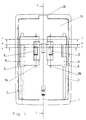
- Fig. 1
- die Armlehne als Draufsicht,
- Fig. 2
- die Grundplatte der Armlehne mit dem Verstellmechanismus in perspektivischer Darstellung,
- Fig. 3
- einen Schnitt gemäß der Linie A-A in Fig. 1,
- Fig. 4
- einen Schnitt gemäß der Linie B-B in Fig. 1,
- Fig. 5
- einen Schnitt gemäß der Linie C-C in Fig. 1 und
- Fig. 6
- einen Schnitt gemäß der Linie D-D in Fig. 1.
In der Ausgangslage sind die linearbeweglichen Teile der Armlehne durch eine oder mehrere Formfedern 13, die zwischen der Grundplatte 1 und dem Führungsprofil 9a des Auflageelementes 9 gegen eine unerwünschte Bewegung, z.B. bei Bremsvorgängen des Fahrzeuges, gesichert. Wie in Fig. 6 gezeigt, sind die Formfedern 13 an der Unterseite des Führungsprofils 9a des Auflageelementes 9 befestigt. Durch Überwindung der Vorspannung der Formfedern 13 kann der Bediener die Armauflage 10 in Längsrichtung in die von ihm gewünschte Stellung verschieben, durch eine Linearbewegung der in beiden Führungen 6 geführten Führungsstangen 7. In der Ausgangslage drücken die Federn 5 die Hebelabschnitte 4b nach oben, bis zum Anschlag der Hebelabschnitte 4a an die Innenseite 2a der Lagerböcke 2. Dabei geben die Backen 4c der Hebelabschnitte 4a das Führungsprofil 9a des Auflageelemente 9 frei. In diesem Zustand ist das Auflageelement 9 mit der Armauflage 10 in bezug auf die Grundplatte 1 geringfügig angehoben, z. B. um eine Höhe von 3 mm, wie in den Figuren 3 bis 5 gezeigt. Durch eine geringfügige Belastung der Armauflage 10, z.B. beim Auflegen des Armes, werden die Hebelabschnitte 4b der beiden Hebel 4 gegen die Vorspannung der Federn 5 nach unten und dabei gleichzeitig die Backen 4c mit ihren Reibflächen 4d gegen das Führungsprofil 9a der Auflageelemente 9 gedrückt und dieses in seiner momentanen Position arretiert. Nach einer Entlastung der Armauflage kann diese vom Bediener wieder in eine andere Position längsverschoben werden.
Claims (12)
- Armlehne mit beweglicher Armauflage, insbesondere für Fahrzeuge, bestehend aus einem Auflageelement und einer Armauflage, wobei zur Linearführung der Armauflage ein Paar parallel beabstandeter Führungsstangen und jeweils eine dazugehörige Führung angeordnet sind, dadurch gekennzeichnet, daß die Führungsstangen (7) in den Führungen (6) linearbeweglich angeordnet und mit dem Auflageelement (9) fest verbunden sind, und die Führungsstangen (7) mit einer Einstell- und Bremsvorrichtung (2, 4, 5) verbunden sind, durch die im Entlastungszustand der Armauflage (10) die Führungsstangen (7) in Längsrichtung verschiebbar sind und im Belastungszustand der Armauflage (10) die Führungsstangen (7) in der jeweiligen Stellung arretiert sind.
- Armlehne nach Anspruch 1, dadurch gekennzeichnet, daß jede der Führungen (6) an einem Hebel (4) angeordnet ist, die Hebel (4) in getrennten Lagerböcken (2) einer gemeinsamen Grundplatte (1) drehbar aufgenommen sind und mittels Federn (5) unabhängig voneinander gegen einen Anschlag (2a) gedrückt sind, wodurch die Führungsstangen (7) um einen definierten Abstand zu der Grundplatte (1) angehoben sind, und das Auflageelement (9) eine längliche Führung (9a) besitzt, die sich in Einbaulage in Längsrichtung zwischen den beiden Lagerböcken (2) befindet, und im Belastungszustand der Armauflage (10) die Hebel (4) gegen die Führung (9a) des Auflagelementes (9) gedrückt sind und im Entlastungszustand der Armauflage (10) die Hebel (4) wieder ihre Ausgangslage einnehmen.
- Armlehne nach einem der Ansprüche 1 oder 2, dadurch gekennzeichnet, daß die Lagerböcke (2) symmetrisch zur Längsachse parallel beabstandet zueinander angeordnet sind und jeweils an ihrer nach innen gerichteten Längsseite eine drehgelenkige Halterung (3) mit einer Drehachse (3a) zur Aufnahme des jeweiligen Hebels (4) aufweisen.
- Armlehne nach einem der Ansprüche 1 bis 3, dadurch gekennzeichnet, daß jeder Hebel (4) einen kurzen, nach unten abgewinkelten Abschnitt (4a) und einen parallel zur Oberseite des Lagerbockes (2) verlaufenden Abschnitt (4b) aufweist und die Drehachse (3a) im Abwinklungsbereich zwischen den beiden Abschnitten (4a, 4b) angeordnet ist.
- Armlehne nach einem der Ansprüche 1 bis 4, dadurch gekennzeichnet, daß am Ende des kurzen nach unten abgewinkelten Abschnittes (4a) des Hebels (4) zwei beabstandete Backen (4c) angeordnet sind, die eine in der vertikalen Ebene liegende Reibfläche (4d) besitzen.
- Armlehne nach einem der Ansprüche 1 bis 5, dadurch gekennzeichnet, daß die Führungen (6) zur Aufnahme der Führungsstangen (7) an den parallel zur Oberseite des Lagerbockes (2) verlaufenden Abschnitten (4b) der Hebel (4) angeordnet sind.
- Armlehne nach einem der Ansprüche 1 bis 6, dadurch gekennzeichnet, daß die Federn (5) im mittleren Bereich der Drehachse (3a) angeordnet sind.
- Armlehne nach einem der Ansprüche 1 bis 7, dadurch gekennzeichnet, daß die Führung (9a) des Auflageelementes (9) als Längsprofil ausgebildet ist und sich über die gesamte Länge der Grundplatte (1) erstreckt.
- Armlehne nach einem der Ansprüche 1 bis 8, dadurch gekennzeichnet, daß sich die Führung (9a) des Auflageelmentes (9) mit einem geringen Spiel zwischen den Backen (4c) der Hebel (4) befindet.
- Armlehne nach einem der Ansprüche 1 bis 9, dadurch gekennzeichnet, daß zwischen der Grundplatte (1) und der Führung (9a) des Auflageelementes (9) eine oder mehrere Formfedern (13) angeordnet sind.
- Armlehne nach einem der Ansprüche 1 bis 10, dadurch gekennzeichnet, daß der Verstellweg der in Längsrichtung beweglichen Führungsstangen (7) in einem Bereich von 80 bis 120 mm liegt.
- Armlehne nach einem der Ansprüche 1 bis 11, dadurch gekennzeichnet, daß die Grundplatte (1) an einem verstellbaren Armlehnenträger befestigt ist oder im Bereich der Vordersitze eines Fahrzeuges fest mit der Mittelkonsole verbunden ist.
Applications Claiming Priority (2)
| Application Number | Priority Date | Filing Date | Title |
|---|---|---|---|
| DE20100902U | 2001-01-17 | ||
| DE20100902U DE20100902U1 (de) | 2001-01-17 | 2001-01-17 | Armlehne mit beweglicher Armauflage, insbesondere für Fahrzeuge |
Publications (3)
| Publication Number | Publication Date |
|---|---|
| EP1225089A2 true EP1225089A2 (de) | 2002-07-24 |
| EP1225089A3 EP1225089A3 (de) | 2003-12-17 |
| EP1225089B1 EP1225089B1 (de) | 2008-04-09 |
Family
ID=7951791
Family Applications (1)
| Application Number | Title | Priority Date | Filing Date |
|---|---|---|---|
| EP02000627A Expired - Lifetime EP1225089B1 (de) | 2001-01-17 | 2002-01-11 | Armlehne mit beweglicher Armauflage, insbesondere für Fahrzeuge |
Country Status (3)
| Country | Link |
|---|---|
| EP (1) | EP1225089B1 (de) |
| AT (1) | ATE391632T1 (de) |
| DE (2) | DE20100902U1 (de) |
Cited By (5)
| Publication number | Priority date | Publication date | Assignee | Title |
|---|---|---|---|---|
| WO2005035303A1 (en) * | 2003-09-24 | 2005-04-21 | Johnson Controls Technology Company | Sliding armrest |
| EP1619070A1 (de) * | 2004-07-21 | 2006-01-25 | Euramax Industries S.A. | Führungsvorrichtung für eine bewegliche Einheit |
| US7029049B2 (en) | 2001-06-19 | 2006-04-18 | Johnson Controls Technology Company | Adjustable armrest |
| DE102005060196B4 (de) * | 2005-05-26 | 2012-12-06 | Intaga Gmbh | Armlehne für einen Sitz im Innenraum eines Kraftfahrzeuges |
| EP2308717A3 (de) * | 2009-10-08 | 2013-12-04 | Linde Material Handling GmbH | Verstellbare Armlehne einer mobilen Arbeitsmaschine, insbesondere eines Flurförderzeugs |
Families Citing this family (2)
| Publication number | Priority date | Publication date | Assignee | Title |
|---|---|---|---|---|
| DE20214711U1 (de) | 2002-09-23 | 2004-02-19 | Seeber Ag & Co. Kg | Auf einem Träger abgestützter Deckel |
| DE202008013566U1 (de) * | 2008-10-13 | 2010-03-04 | Brose Fahrzeugteile Gmbh & Co. Kommanditgesellschaft, Coburg | Längsverstellbare Mittelarmlehne für ein Kraftfahrzeug |
Citations (2)
| Publication number | Priority date | Publication date | Assignee | Title |
|---|---|---|---|---|
| DE19846030C1 (de) | 1998-10-06 | 2000-02-10 | Eldra Kunststofftechnik Gmbh | Armlehne |
| DE19915469A1 (de) | 1999-04-06 | 2000-10-19 | Grammer Ag | Armlehne für einen Sitz |
Family Cites Families (4)
| Publication number | Priority date | Publication date | Assignee | Title |
|---|---|---|---|---|
| DE8437440U1 (de) | 1985-03-28 | Audi Nsu Auto Union Ag, 7107 Neckarsulm | Mittelkonsole zwischen den Vordersitzen eines Kraftfahrzeuges | |
| DE3807880A1 (de) | 1988-03-10 | 1989-09-21 | Daimler Benz Ag | Mittelkonsole fuer kraftwagen |
| DE19611892C1 (de) | 1996-03-26 | 1997-09-11 | Daimler Benz Ag | Mittelkonsole für einen Personenkraftwagen |
| DE19717301B4 (de) * | 1997-04-24 | 2006-10-26 | Bock 1 Gmbh &Co. | Universal-Sitzträgerplatte für Bürostühle |
-
2001
- 2001-01-17 DE DE20100902U patent/DE20100902U1/de not_active Expired - Lifetime
-
2002
- 2002-01-11 EP EP02000627A patent/EP1225089B1/de not_active Expired - Lifetime
- 2002-01-11 DE DE50212040T patent/DE50212040D1/de not_active Expired - Lifetime
- 2002-01-11 AT AT02000627T patent/ATE391632T1/de not_active IP Right Cessation
Patent Citations (2)
| Publication number | Priority date | Publication date | Assignee | Title |
|---|---|---|---|---|
| DE19846030C1 (de) | 1998-10-06 | 2000-02-10 | Eldra Kunststofftechnik Gmbh | Armlehne |
| DE19915469A1 (de) | 1999-04-06 | 2000-10-19 | Grammer Ag | Armlehne für einen Sitz |
Cited By (5)
| Publication number | Priority date | Publication date | Assignee | Title |
|---|---|---|---|---|
| US7029049B2 (en) | 2001-06-19 | 2006-04-18 | Johnson Controls Technology Company | Adjustable armrest |
| WO2005035303A1 (en) * | 2003-09-24 | 2005-04-21 | Johnson Controls Technology Company | Sliding armrest |
| EP1619070A1 (de) * | 2004-07-21 | 2006-01-25 | Euramax Industries S.A. | Führungsvorrichtung für eine bewegliche Einheit |
| DE102005060196B4 (de) * | 2005-05-26 | 2012-12-06 | Intaga Gmbh | Armlehne für einen Sitz im Innenraum eines Kraftfahrzeuges |
| EP2308717A3 (de) * | 2009-10-08 | 2013-12-04 | Linde Material Handling GmbH | Verstellbare Armlehne einer mobilen Arbeitsmaschine, insbesondere eines Flurförderzeugs |
Also Published As
| Publication number | Publication date |
|---|---|
| EP1225089A3 (de) | 2003-12-17 |
| ATE391632T1 (de) | 2008-04-15 |
| EP1225089B1 (de) | 2008-04-09 |
| DE20100902U1 (de) | 2001-06-07 |
| DE50212040D1 (de) | 2008-05-21 |
Similar Documents
| Publication | Publication Date | Title |
|---|---|---|
| DE19611892C1 (de) | Mittelkonsole für einen Personenkraftwagen | |
| EP0111165B1 (de) | Sitzgestell mit Hangausgleich für Fahrzeuge, insbesondere Ackerschlepper | |
| WO2014001013A1 (de) | Verstelleinrichtung zum verstellen der position eines windschilds | |
| DE102014204558A1 (de) | Fahrzeugsitz | |
| EP0844132B1 (de) | Längsverstellvorrichtung für Sitze, insbesondere Kraftfahrzeugsitze | |
| DE19730131A1 (de) | Fahrzeugsitz | |
| DE2716549A1 (de) | Fahrzeugsitzschieneneinstellvorrichtung | |
| EP1348593B1 (de) | Armlehne mit beweglicher Armauflage, insbesondere für Fahrzeuge | |
| DE102013106708A1 (de) | Fahrzeugsitz und Nutzkraftfahrzeug mit wenigstens einem Fahrzeugsitz | |
| DE2522074B2 (de) | Feststellvorrichtung für die Gleitführung eines in Längsrichtung verschiebbaren Kfz-Sitzes | |
| DE19628861B4 (de) | Fahrzeugsitz, insbesondere für einen Personenkraftwagen | |
| DE602005003559T2 (de) | Sitzanordnung mit kippbarer Rückenlehne für ein Kraftfahrzeug | |
| EP1225089A2 (de) | Armlehne mit beweglicher Armauflage, insbesondere für Fahrzeuge | |
| EP3873775B1 (de) | Verstelleinrichtung zum verlagern eines sitzes, kraftfahrzeug und verfahren zum verlagern eines sitzes | |
| DE102020111898A1 (de) | Beinstützensystem für sitzbaugruppe | |
| EP3243696A1 (de) | Armlehne | |
| DE102017122158B4 (de) | Verstellbare Fußstütze und Verfahren zur Anpassung der Fußstütze für einen Insassen | |
| DE3129063C2 (de) | Kopfstütze für Fahrzeugsitze | |
| DE102014001980B3 (de) | Kopfstütze für Fahrzeugsitze | |
| DE3531992C2 (de) | Verstelleinrichtung für eine in ihrer Neigung verstellbare Kraftfahrzeug-Hintersitzlehne | |
| EP1070651B1 (de) | Verstellvorrichtung für ein Mantelrohr einer Lenkungsanlage eines Kraftfahrzeugs | |
| DE10202914B4 (de) | Ausfahrbarer Ladeboden für ein Fahrzeug | |
| DE4038279A1 (de) | Sitz, insbesondere kraftfahrzeugsitz mit wenigstens einer schenkelstuetze | |
| DE102009036896B3 (de) | Kopfstütze für Fahrzeugsitze | |
| DE202017100536U1 (de) | Manuell längsverstellbarer Kraftfahrzeugsitz |
Legal Events
| Date | Code | Title | Description |
|---|---|---|---|
| PUAI | Public reference made under article 153(3) epc to a published international application that has entered the european phase |
Free format text: ORIGINAL CODE: 0009012 |
|
| AK | Designated contracting states |
Kind code of ref document: A2 Designated state(s): AT BE CH CY DE DK ES FI FR GB GR IE IT LI LU MC NL PT SE TR |
|
| AX | Request for extension of the european patent |
Free format text: AL;LT;LV;MK;RO;SI |
|
| PUAL | Search report despatched |
Free format text: ORIGINAL CODE: 0009013 |
|
| AK | Designated contracting states |
Kind code of ref document: A3 Designated state(s): AT BE CH CY DE DK ES FI FR GB GR IE IT LI LU MC NL PT SE TR |
|
| AX | Request for extension of the european patent |
Extension state: AL LT LV MK RO SI |
|
| RIC1 | Information provided on ipc code assigned before grant |
Ipc: 7B 60N 2/46 A Ipc: 7A 47C 7/54 B |
|
| 17P | Request for examination filed |
Effective date: 20040319 |
|
| AKX | Designation fees paid |
Designated state(s): AT BE CH CY DE DK ES FI FR GB GR IE IT LI LU MC NL PT SE TR |
|
| RAP1 | Party data changed (applicant data changed or rights of an application transferred) |
Owner name: KTSN KUNSTSTOFFTECHNIK SACHSEN GMBH & CO. KG |
|
| GRAP | Despatch of communication of intention to grant a patent |
Free format text: ORIGINAL CODE: EPIDOSNIGR1 |
|
| GRAS | Grant fee paid |
Free format text: ORIGINAL CODE: EPIDOSNIGR3 |
|
| GRAA | (expected) grant |
Free format text: ORIGINAL CODE: 0009210 |
|
| AK | Designated contracting states |
Kind code of ref document: B1 Designated state(s): AT BE CH CY DE DK ES FI FR GB GR IE IT LI LU MC NL PT SE TR |
|
| REG | Reference to a national code |
Ref country code: GB Ref legal event code: FG4D Free format text: NOT ENGLISH |
|
| REG | Reference to a national code |
Ref country code: CH Ref legal event code: EP |
|
| REG | Reference to a national code |
Ref country code: IE Ref legal event code: FG4D Free format text: LANGUAGE OF EP DOCUMENT: GERMAN |
|
| REF | Corresponds to: |
Ref document number: 50212040 Country of ref document: DE Date of ref document: 20080521 Kind code of ref document: P |
|
| NLV1 | Nl: lapsed or annulled due to failure to fulfill the requirements of art. 29p and 29m of the patents act | ||
| PG25 | Lapsed in a contracting state [announced via postgrant information from national office to epo] |
Ref country code: NL Free format text: LAPSE BECAUSE OF FAILURE TO SUBMIT A TRANSLATION OF THE DESCRIPTION OR TO PAY THE FEE WITHIN THE PRESCRIBED TIME-LIMIT Effective date: 20080409 Ref country code: FI Free format text: LAPSE BECAUSE OF FAILURE TO SUBMIT A TRANSLATION OF THE DESCRIPTION OR TO PAY THE FEE WITHIN THE PRESCRIBED TIME-LIMIT Effective date: 20080409 Ref country code: PT Free format text: LAPSE BECAUSE OF FAILURE TO SUBMIT A TRANSLATION OF THE DESCRIPTION OR TO PAY THE FEE WITHIN THE PRESCRIBED TIME-LIMIT Effective date: 20080909 Ref country code: ES Free format text: LAPSE BECAUSE OF FAILURE TO SUBMIT A TRANSLATION OF THE DESCRIPTION OR TO PAY THE FEE WITHIN THE PRESCRIBED TIME-LIMIT Effective date: 20080720 |
|
| REG | Reference to a national code |
Ref country code: IE Ref legal event code: FD4D |
|
| EN | Fr: translation not filed | ||
| PG25 | Lapsed in a contracting state [announced via postgrant information from national office to epo] |
Ref country code: SE Free format text: LAPSE BECAUSE OF FAILURE TO SUBMIT A TRANSLATION OF THE DESCRIPTION OR TO PAY THE FEE WITHIN THE PRESCRIBED TIME-LIMIT Effective date: 20080709 Ref country code: DK Free format text: LAPSE BECAUSE OF FAILURE TO SUBMIT A TRANSLATION OF THE DESCRIPTION OR TO PAY THE FEE WITHIN THE PRESCRIBED TIME-LIMIT Effective date: 20080409 Ref country code: IE Free format text: LAPSE BECAUSE OF FAILURE TO SUBMIT A TRANSLATION OF THE DESCRIPTION OR TO PAY THE FEE WITHIN THE PRESCRIBED TIME-LIMIT Effective date: 20080409 |
|
| PLBE | No opposition filed within time limit |
Free format text: ORIGINAL CODE: 0009261 |
|
| STAA | Information on the status of an ep patent application or granted ep patent |
Free format text: STATUS: NO OPPOSITION FILED WITHIN TIME LIMIT |
|
| 26N | No opposition filed |
Effective date: 20090112 |
|
| PG25 | Lapsed in a contracting state [announced via postgrant information from national office to epo] |
Ref country code: FR Free format text: LAPSE BECAUSE OF FAILURE TO SUBMIT A TRANSLATION OF THE DESCRIPTION OR TO PAY THE FEE WITHIN THE PRESCRIBED TIME-LIMIT Effective date: 20090130 |
|
| PG25 | Lapsed in a contracting state [announced via postgrant information from national office to epo] |
Ref country code: IT Free format text: LAPSE BECAUSE OF FAILURE TO SUBMIT A TRANSLATION OF THE DESCRIPTION OR TO PAY THE FEE WITHIN THE PRESCRIBED TIME-LIMIT Effective date: 20080409 Ref country code: MC Free format text: LAPSE BECAUSE OF NON-PAYMENT OF DUE FEES Effective date: 20090131 |
|
| REG | Reference to a national code |
Ref country code: CH Ref legal event code: PL |
|
| GBPC | Gb: european patent ceased through non-payment of renewal fee |
Effective date: 20090111 |
|
| PG25 | Lapsed in a contracting state [announced via postgrant information from national office to epo] |
Ref country code: CY Free format text: LAPSE BECAUSE OF FAILURE TO SUBMIT A TRANSLATION OF THE DESCRIPTION OR TO PAY THE FEE WITHIN THE PRESCRIBED TIME-LIMIT Effective date: 20080409 |
|
| PG25 | Lapsed in a contracting state [announced via postgrant information from national office to epo] |
Ref country code: CH Free format text: LAPSE BECAUSE OF NON-PAYMENT OF DUE FEES Effective date: 20090131 Ref country code: LI Free format text: LAPSE BECAUSE OF NON-PAYMENT OF DUE FEES Effective date: 20090131 |
|
| PG25 | Lapsed in a contracting state [announced via postgrant information from national office to epo] |
Ref country code: GB Free format text: LAPSE BECAUSE OF NON-PAYMENT OF DUE FEES Effective date: 20090111 |
|
| PG25 | Lapsed in a contracting state [announced via postgrant information from national office to epo] |
Ref country code: BE Free format text: LAPSE BECAUSE OF NON-PAYMENT OF DUE FEES Effective date: 20090131 |
|
| PG25 | Lapsed in a contracting state [announced via postgrant information from national office to epo] |
Ref country code: AT Free format text: LAPSE BECAUSE OF NON-PAYMENT OF DUE FEES Effective date: 20090111 |
|
| PG25 | Lapsed in a contracting state [announced via postgrant information from national office to epo] |
Ref country code: GR Free format text: LAPSE BECAUSE OF FAILURE TO SUBMIT A TRANSLATION OF THE DESCRIPTION OR TO PAY THE FEE WITHIN THE PRESCRIBED TIME-LIMIT Effective date: 20080710 |
|
| PG25 | Lapsed in a contracting state [announced via postgrant information from national office to epo] |
Ref country code: LU Free format text: LAPSE BECAUSE OF NON-PAYMENT OF DUE FEES Effective date: 20090111 |
|
| PG25 | Lapsed in a contracting state [announced via postgrant information from national office to epo] |
Ref country code: TR Free format text: LAPSE BECAUSE OF FAILURE TO SUBMIT A TRANSLATION OF THE DESCRIPTION OR TO PAY THE FEE WITHIN THE PRESCRIBED TIME-LIMIT Effective date: 20080409 |
|
| REG | Reference to a national code |
Ref country code: DE Ref legal event code: R082 Ref document number: 50212040 Country of ref document: DE Representative=s name: WEIDNER STERN JESCHKE PATENTANWAELTE PARTNERSC, DE |
|
| REG | Reference to a national code |
Ref country code: DE Ref legal event code: R079 Ref document number: 50212040 Country of ref document: DE Free format text: PREVIOUS MAIN CLASS: B60N0002460000 Ipc: B60N0002750000 |
|
| REG | Reference to a national code |
Ref country code: DE Ref legal event code: R082 Ref document number: 50212040 Country of ref document: DE Representative=s name: WEIDNER STERN JESCHKE PATENTANWAELTE PARTNERSC, DE Ref country code: DE Ref legal event code: R081 Ref document number: 50212040 Country of ref document: DE Owner name: EISSMANN AUTOMOTIVE KTSN GMBH, DE Free format text: FORMER OWNER: KTSN KUNSTSTOFFTECHNIK SACHSEN GMBH & CO. KG, 01796 PIRNA, DE |
|
| REG | Reference to a national code |
Ref country code: DE Ref legal event code: R081 Ref document number: 50212040 Country of ref document: DE Owner name: EISSMANN AUTOMOTIVE KTSN GMBH, DE Free format text: FORMER OWNER: MINDA KTSN PLASTIC SOLUTIONS GMBH & CO. KG, 01796 PIRNA, DE Ref country code: DE Ref legal event code: R082 Ref document number: 50212040 Country of ref document: DE Representative=s name: WEIDNER STERN JESCHKE PATENTANWAELTE PARTNERSC, DE |
|
| PGFP | Annual fee paid to national office [announced via postgrant information from national office to epo] |
Ref country code: DE Payment date: 20200921 Year of fee payment: 20 |
|
| REG | Reference to a national code |
Ref country code: DE Ref legal event code: R082 Ref document number: 50212040 Country of ref document: DE Representative=s name: BARDEHLE PAGENBERG PARTNERSCHAFT MBB PATENTANW, DE |
|
| REG | Reference to a national code |
Ref country code: DE Ref legal event code: R071 Ref document number: 50212040 Country of ref document: DE |