EP1223672A2 - Elektronische Vorrichtung - Google Patents
Elektronische Vorrichtung Download PDFInfo
- Publication number
- EP1223672A2 EP1223672A2 EP01130876A EP01130876A EP1223672A2 EP 1223672 A2 EP1223672 A2 EP 1223672A2 EP 01130876 A EP01130876 A EP 01130876A EP 01130876 A EP01130876 A EP 01130876A EP 1223672 A2 EP1223672 A2 EP 1223672A2
- Authority
- EP
- European Patent Office
- Prior art keywords
- voltage
- operation button
- button
- switch
- pressed
- Prior art date
- Legal status (The legal status is an assumption and is not a legal conclusion. Google has not performed a legal analysis and makes no representation as to the accuracy of the status listed.)
- Granted
Links
Images


Classifications
-
- H—ELECTRICITY
- H02—GENERATION; CONVERSION OR DISTRIBUTION OF ELECTRIC POWER
- H02H—EMERGENCY PROTECTIVE CIRCUIT ARRANGEMENTS
- H02H11/00—Emergency protective circuit arrangements for preventing the switching-on in case an undesired electric working condition might result
-
- H—ELECTRICITY
- H01—ELECTRIC ELEMENTS
- H01H—ELECTRIC SWITCHES; RELAYS; SELECTORS; EMERGENCY PROTECTIVE DEVICES
- H01H2239/00—Miscellaneous
- H01H2239/01—Miscellaneous combined with other elements on the same substrate
- H01H2239/012—Decoding impedances
-
- H—ELECTRICITY
- H01—ELECTRIC ELEMENTS
- H01H—ELECTRIC SWITCHES; RELAYS; SELECTORS; EMERGENCY PROTECTIVE DEVICES
- H01H2239/00—Miscellaneous
- H01H2239/03—Avoiding erroneous switching
-
- H—ELECTRICITY
- H01—ELECTRIC ELEMENTS
- H01H—ELECTRIC SWITCHES; RELAYS; SELECTORS; EMERGENCY PROTECTIVE DEVICES
- H01H2239/00—Miscellaneous
- H01H2239/066—Duplication of control panel, e.g. duplication of some keys
Definitions
- the present invention relates to an electronic device having an operation button manipulated by pressing it.
- an operation button to be manipulated by pressing and having the same function as the operation button as provided in the device main body is placed on the steering wheel. It is intended to manipulate the operation button by remote control by connecting the operation button on the steering wheel and the device main body.
- the operation button provided on the steering wheel is usable simultaneously with the operation button of the device main body. Out of these operation buttons, the operation button pressed first is put in effect, and the operation according to manipulation of that operation button is carried out.
- An example of operation button placed on the steering wheel to be manipulated by pressing is a volume UP/DOWN button for controlling the volume level of the power amplifier.
- a volume UP/DOWN button for controlling the volume level of the power amplifier.
- cperation signals showing the duration of the pressing operation and number of times of the pressing operation are supplied to the microcomputer.
- the microcomputer controls the power amplifier according to the operation signals to vary the gain thereof.
- the pressed volume UP/DOWN button may be stuck in the pressed state without returning to the initial state.
- the operation signal from the volume UP button on the steering wheel is supplied to the microcomputer continuously from this moment.
- the volume level of the power amplifier increases, and the sound volume delivered from the speaker goes too much higher. As a result, the driver is exposed to an intolerable sound delivered from the speaker.
- the present invention has been achieved in order to solve the above problems. It is an object of this invention to provide an electronic device configured not to operate according to an operation signal from an operation button in pressed state, if the operation button is in the pressed state when the power is supplied.
- an electronic device including: an operation button to be manipulated by pressing; a judging unit for judging whether or not a voltage changed by pressing the operation button is equal to a specified value when an electric power is supplied; and a control unit for preventing a control corresponding to the signal from the operation button in pressed state from being executed when the judging unit judges that the voltage is not equal to the specified value.
- an operation button to be manipulated by a user is provided.
- the electronic power is supplied to the electronic device, it is judged whether or not a voltage changed by pressing the operation button is equal to a specified value. If the voltage is equal to the specified value, the corresponding control is executed. On the contrary, if the voltage is not equal to the specified value, the corresponding control is not executed. For example, if the operation button is improperly being continuously pressed for some reason, the voltage does not take the specified value, and hence the corresponding control is prevented.
- the specified value may be a voltage showing the state that the operation button is not pressed.
- an electronic device including: a first operation button provided in a device main body to be manipulated by pressing; a second operation button provided at a position remote from the device main body to be manipulated by pressing; a judging unit for judging whether a voltage changed by pressing of the first operation button and second operation button is equal to a first specified value or a second specified value when an electric power is supplied; and a control unit for preventing a control corresponding to the signal from the second operation button in pressed state from being executed when the judging unit judges that the voltage is not equal to the first specified value, and for preventing the control corresponding to the signal from the first operation button in pressed state from being executed when the judging unit judges that the voltage is not equal to the second specified value.
- a first operation button to be manipulated by a user is provided on the device main body, and a second operation button is provided remotely from the device main body.
- a voltage changed by pressing the operation button is equal to one of a first specified value and a second specified value. If the voltage is not equal to the first specified value, the control corresponding to pressing the second operation button is not executed. If the voltage is not equal to the second specified value, the control corresponding to the first operation button is not executed. For example, if the operation button is improperly being continuously pressed for some reason, the voltage does not take the specified value, and hence the corresponding control is prevented.
- the specified value may be a voltage showing the state that the operation button is not pressed.
- the first specified value may be a voltage showing the state that the second operation button is not pressed
- the second specified value may be a voltage showing the state that the first operation button is not pressed
- This embodiment relates to a car-mount acoustic device 100 including an UP button to be manipulated for raising the volume level of a power amplifier provided in a device main body, a DOWN button to be manipulated to lower it, and an UP button and a DOWN button placed on a steering wheel having the same functions as the corresponding buttons provided in the device main body. It is noted that, in this invention, the types of operation buttons are not limited to these examples.
- Fig. 1 shows a block diagram of the car-mount acoustic device 100 of the embodiment
- Fig. 2 shows a specific circuit diagram of a remote control unit 20, an operation unit 10a and a voltage supply unit 10b that constitute the car-mount acoustic device 100.
- the car-mount acoustic device 100 includes a device main body 10 and a remote control unit 20.
- the device main body 10 includes an operation unit 10a having an UP button and a DOWN button to be manipulated by the user by pressing, a voltage supply unit 10b for supplying voltage to the operation unit 10a and to the remote control unit 20 through the operation unit 10a, a power amplifier 10c, a volume control circuit 10d for controlling the power amplifier 10c, a microcomputer 10e for controlling the operation in the device, and a power switch 10f.
- the operation unit 10a supplies an operation signal Sh corresponding to the pressing operation to the microcomputer 10e.
- the microcomputer 10a controls the volume control circuit 10d according to this operation signal Sh.
- the remote control unit 20 is provided on a steering wheel 50, and includes an UP button 20a and a DOWN button 20b to be manipulated by the user by pressing.
- the remote control unit 20 is connected to the device main body 10 by wiring, etc.
- the UP button 20a or DOWN button 20b is pressed after voltage is supplied from the voltage supply unit 10b, the remote control unit 20 supplies an operation signal Se corresponding to the pressing operation to the microcomputer 10e.
- the microcomputer 10e controls the volume control circuit 10d according to this operation signal Se.
- Reference numeral 30 indicates a battery for supplying power to the device main body 10. That is to say, by turning on the power switch 10f, power is supplied from the battery 30, and the device main body 10 is activated.
- the voltage supply unit 10b is configured by connecting two resistors Ra, Rd and a voltage shifting diode Vd in series between a 5V power source and an earth potential (GND), and by connecting a noise eliminating capacitor C1 to the resistor Rd in a parallel fashion.
- An intersection voltage of the resistor Ra and the diode Vd is supplied to the microcomputer 10e.
- An intersection voltage of the diode Vd and the resistor Rd is supplied to the operation unit 10a and the remote control unit 20.
- the operation unit 10a includes two resistors Rh1, Rh2 and two switches SW1, SW2.
- the resistor Rh1 is connected in series to one end of the switch SW1 and one end of the resistor Rd, and the resistor Rh2 is connected in series to one end of the switch SW2 and one end of the switch SW1.
- the remote control unit 20 includes two resistors Rh3, Rh4 and two switches SW3, SW4.
- the resistor Rh3 is connected in series to one end of the switch SW3 and one end of the switch SW2, and the resistor Rh4 is connected in series to one end of the switch SW4 and one end of the switch SW3.
- the operation unit 10a and the remote control unit 20 have four resistors Rh1 to Rh4 connected in series to the intersection of the diode Vd and resistor Rd of the voltage supply unit 10b, and are designed to connect the intersections of the respective resistors to the earth potential by means or the switches SW1 to SW4.
- the switch SW1 corresponds to the UP button of the operation unit 10a
- the switch SW2 corresponds to the DOWN button of the operation unit 10a
- the switch SW3 corresponds to the UP button 20a of the remote control unit 20
- the switch SW4 corresponds to the DOWN button 20b of the remote control unit 20.
- the operation unit 10a, voltage supply unit 10b and remote control unit 20 thus designed are connected in the following mutual relations when the switches SW1 to SW4 are closed.
- the resistance value of the resistor Ra is 470 ⁇
- the resistance value of the resistor Rd is 10k ⁇
- the forward voltage of the diode Vd (the forward voltage varies with the supplied current value) is a constant 0.6 V.
- a voltage of about 4.8 V is output at the intersection of the resistor Ra and the diode Vd.
- the voltage of about 4.8V, generated at the intersection of the voltage supply unit 10 is a voltage generated when all switches SW1 to SW4 are open, that is to say, no operation button is pressed. This voltage will be called “reference voltage” in the following explanation.
- the voltage supply unit 10b outputs a voltage of about 2.3V at the intersection of the resistor Ra and the diode Vd.
- the voltage supply unit 1Ob outputs a voltage of about 4.3V at the intersection of the resistor Ra and the diode Vd.
- the resistors Rh1 to Rh4 are connected in parallel to the resistor Rd of the voltage supply unit 10b when any one of the switches SW is closed.
- the resistance value of the resistor Rd varies depending on the opened or closed state of the switches SW1 to SW4, so that different voltages can be generated at the intersection of the resistor Ra and the diode Vd of the voltage supply unit 10b. Therefore, by detecting the intersection voltage output from the voltage supply unit 10b, the microcomputer 10e can judge if all switches SW1 to SW4 are open, or which switch is closed.
- Fig. 3 shows changes of intersection voltage of the resistor Ra and the diode Vd with the passage of the time.
- the intersection voltage of the voltage supply unit 10b increases to the reference voltage. Then, when the switch SW3 is closed, that is to say, the UP button 20a is pressed, the intersection voltage of the voltage supply unit 10b decreases from the reference voltage to about 3.5V.
- the intersection voltage of the voltage supply unit 10b increases again to the reference voltage.
- the switch SW2 is closed, that is to say, when the DOWN button of the operation unit 10a is pressed, the intersection voltage of the voltage supply unit 10b decreases from the reference voltage to about 2.3V.
- an ordinary volume level fall operation is carried out. It is the same in the other switches SW1, SW4, and the intersection voltage of the voltage supply unit 10b decreases from the reference voltage to the voltage generated when each switch is closed, and the operation depending on the pressing manipulation is carried out.
- the microcomputer 10e detects the intersection voltage, and if the reference voltage is not detected, it is judged that any one of the switches SW1 to SW4 is in closed state, i.e., in pressed state. If any one of the reference voltage, the voltage of about 1.0 V and the voltage of about 2.3 V is not detected, it is judged that either switch SW3 or switch SW4 is in closed state, i.e., in pressed state. If any one of the reference voltages, the voltage of about 3.5V and the voltage of about 4.3 V is not detected, it is judged that either switch SW1 or switch SW2 is in closed state, i.e., in pressed state.
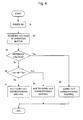
- the control operation of the microcomputer 10e in this embodiment will be explained according to the operation flow in Fig. 5.
- the operation flow shown in Fig. 4 is an operation program preliminarily stored in a storage unit (not shown) of the car-mount acoustic device 100, and it is started when the power switch 10f is manipulated.
- step S1 the microcomputer 10e detects that the user turns on the power switch 10f of the device main body 10, and starts to take the intersection voltage output from the voltage supply unit 10b (step S2).
- step S3 it is judged if the intersection voltage is equal to the reference voltage or not. If the intersection voltage is judged to be equal to the reference voltage (YES) at step 53, the control operation, that corresponds to the operation signal from the operation button pressed in the operation unit 10a or the remote control unit 20, is executed (step S5).
- the microcomputer 10e when receiving an intersection voltage of about 3.5 V from the voltage supply unit 10b, judges that the UP button 20a of the remote control unit 20 is pressed, generates a control signal from the operation signal Se according to the duration of operation or number of times of operation supplied from the switch SW3, and supplies it to the volume control circuit 10d.
- the volume control circuit 10d increases the output level of the power amplifier 10c on the basis of the control signal supplied from the microcomputer 10e.
- the microcomputer 10e judges that the DOWN button 20b of the remote control unit 20 is pressed, generates a control signal from the operation signal Se supplied from the switch SW4, and supplies it to the volume control circuit 10d.
- the volume control circuit 10d lowers the output level of the power amplifier 10c on the basis of the control signal supplied from the microcomputer 10e.
- the microcomputer 10e judges that the UP button of the operation unit 10a is pressed, generates a control signal from the operation signal Sh according to the duration of operation or number of times of operation supplied from the switch SW1, and supplies it to the volume control circuit 10d.
- the volume control circuit 10d increases the output level of the power amplifier 10c on the basis of the control signal supplied from the microcomputer 10e.
- the microcomputer 10e judges that the DOWN button of the operation unit 10a is pressed, generates a control signal from the operation signal Sh supplied from the switch SW2, and supplies it to the volume control circuit 10d.
- the volume control circuit 10d lowers the output level of the power amplifier 10c on the basis of the control signal supplied from the microcomputer 10e.
- step S3 when the microcomputer 10e judges that the intersection voltage received from the voltage supply unit 10b is not equal to the reference voltage (NO), the microcomputer 10e judges if the intersection voltage is a voltage of about 1.0 V or a voltage of about 2.3 V, If judged to be neither voltage (NO), that is to say, if judged to be either a voltage of about 3.5 V or a voltage of about 4.3V, the control operation corresponding to the operation signal Se from the operation button pressed in the remote control unit 20 is not carried out (step S6).
- the switch SW3 or switch SW4 When the power switch 10f is turned on, the switch SW3 or switch SW4 is closed, that is to say, the UP button 10a or DOWN button 20b of the remote control unit 20 is in pressed state, and the operation signal Se by pressing of the UP button 20a or DOWN button 20b is supplied into the microcomputer 10e.
- the microcomputer 10e already recognizes that the operation button supplying this operation signal Se has been in pressed state. Therefore, the microcomputer 10e does not generate the control signal for this operation signal Se, so that no control is executed on the volume control circuit 10d.
- step S6 the operation in step S6 is terminated. Thereafter, the microcomputer 10e carries out control operation only on the operation signal Sh from the operation buttons of the operation unit 10a mentioned above.
- step S4 when the microcomputer 10e judges that the intersection voltage received from the voltage supply unit 10b is either a voltage of about 1.0 V or a voltage of about 2.3 V (YES), that is to say, neither a voltage of about 3.5V nor a voltags of about 4.3V, control operation is not carried out for the operation signal Sh from the operation button pressed in the operation unit 10a (step S7).
- the microcomputer 10e carries out control operation only on the operation signal Se from the operation buttons of the remote control unit 20 mentioned above.
- the microcomputer 10e detects the change of intersection voltage from the voltage supply unit 10b, and judges presence or absence of operation button that has continuously been in the pressed state due to trouble or which operation button has been in the pressed state, thereby to perform no control corresponding to the operation signal from the operation button kept in pressed state. Therefore, if the power source is turned on while the volume UP button for increasing the volume level of the power amplifier is kept in pressed state, when hearing the sound delivered from the speaker, creation of intolerable situation for the user can be prevented.
- the microcomputer 10e when the power switch 10f of the device main body is turned on, the microcomputer 10e carries out control operation.
- this invention is not limited to this example, and, for instance, the microcomputer 10e may be designed to carry out control operation when the ACC switch provided in the vehicle is turned on.
- the embodiment of the invention is applied to the car-mount acoustic device, but not limited to this example, the invention may be applied in various electronic devices having operation buttons manipulated by pressing, within the scope and true spirit of the invention.
- control operation about the operation signal from such operation button is not carried out by the microcomputer.
- operation button is a volume UP button to be manipulated for increasing the volume level of the power amplifier, when hearing the sound delivered from the speaker, creation of intolerable situation for the user can be prevented.
Landscapes
- Selective Calling Equipment (AREA)
- Keying Circuit Devices (AREA)
Applications Claiming Priority (2)
| Application Number | Priority Date | Filing Date | Title |
|---|---|---|---|
| JP2000398642 | 2000-12-27 | ||
| JP2000398642A JP2002203442A (ja) | 2000-12-27 | 2000-12-27 | 電子機器 |
Publications (3)
| Publication Number | Publication Date |
|---|---|
| EP1223672A2 true EP1223672A2 (de) | 2002-07-17 |
| EP1223672A3 EP1223672A3 (de) | 2004-12-08 |
| EP1223672B1 EP1223672B1 (de) | 2007-07-11 |
Family
ID=18863567
Family Applications (1)
| Application Number | Title | Priority Date | Filing Date |
|---|---|---|---|
| EP20010130876 Expired - Lifetime EP1223672B1 (de) | 2000-12-27 | 2001-12-27 | Elektronische Vorrichtung |
Country Status (4)
| Country | Link |
|---|---|
| US (1) | US6657317B2 (de) |
| EP (1) | EP1223672B1 (de) |
| JP (1) | JP2002203442A (de) |
| DE (1) | DE60129293T2 (de) |
Cited By (1)
| Publication number | Priority date | Publication date | Assignee | Title |
|---|---|---|---|---|
| FR2879803A1 (fr) * | 2004-12-20 | 2006-06-23 | Dav Sa | Dispositif d'activation par surface tactile, notamment pour les commandes d'un vehicule |
Families Citing this family (2)
| Publication number | Priority date | Publication date | Assignee | Title |
|---|---|---|---|---|
| US20150158434A1 (en) * | 2013-12-10 | 2015-06-11 | Hyundai Motor Company | Remote system and method for controlling a vehicle device |
| KR102368020B1 (ko) * | 2017-04-25 | 2022-02-25 | 현대모비스 주식회사 | Adc 방식의 버튼 인식 시스템 및 방법 |
Family Cites Families (8)
| Publication number | Priority date | Publication date | Assignee | Title |
|---|---|---|---|---|
| US4792990A (en) * | 1987-02-27 | 1988-12-20 | Rca Licensing Corporation | Audio amplifier with programmed volume control |
| JP2949995B2 (ja) * | 1992-02-20 | 1999-09-20 | 日産自動車株式会社 | 多重通信装置 |
| JP2949998B2 (ja) * | 1992-02-21 | 1999-09-20 | 日産自動車株式会社 | 通信装置 |
| JP3144453B2 (ja) * | 1994-03-23 | 2001-03-12 | 矢崎総業株式会社 | スイッチ判別機能を備えたスイッチ装置及び操作用スイッチ |
| JPH1097821A (ja) * | 1996-08-01 | 1998-04-14 | Matsushita Electric Ind Co Ltd | 操作装置およびこれを用いた車載用機器の操作装置 |
| JP3692759B2 (ja) * | 1998-01-19 | 2005-09-07 | 株式会社デンソー | 車両用表示装置 |
| DE19860880B4 (de) * | 1998-02-10 | 2006-11-09 | Denso Corp., Kariya | Antrieb für Passagierschutzsystem |
| AT408325B (de) * | 1998-03-13 | 2001-10-25 | Keba Gmbh & Co | Sicherheitsschalteinrichtung für ein handbediengerät zur steuerung von maschinen |
-
2000
- 2000-12-27 JP JP2000398642A patent/JP2002203442A/ja active Pending
-
2001
- 2001-12-27 DE DE2001629293 patent/DE60129293T2/de not_active Expired - Fee Related
- 2001-12-27 US US10/026,829 patent/US6657317B2/en not_active Expired - Fee Related
- 2001-12-27 EP EP20010130876 patent/EP1223672B1/de not_active Expired - Lifetime
Cited By (3)
| Publication number | Priority date | Publication date | Assignee | Title |
|---|---|---|---|---|
| FR2879803A1 (fr) * | 2004-12-20 | 2006-06-23 | Dav Sa | Dispositif d'activation par surface tactile, notamment pour les commandes d'un vehicule |
| WO2006067041A1 (fr) * | 2004-12-20 | 2006-06-29 | Dav | Dispositif d'activation par surface tactile, notamment pour les commandes d'un vehicule |
| US8058577B2 (en) | 2004-12-20 | 2011-11-15 | Dav | Touch-sensitive surface activation device for the controls of a vehicle |
Also Published As
| Publication number | Publication date |
|---|---|
| JP2002203442A (ja) | 2002-07-19 |
| US20020079745A1 (en) | 2002-06-27 |
| EP1223672A3 (de) | 2004-12-08 |
| EP1223672B1 (de) | 2007-07-11 |
| DE60129293T2 (de) | 2008-04-17 |
| DE60129293D1 (de) | 2007-08-23 |
| US6657317B2 (en) | 2003-12-02 |
Similar Documents
| Publication | Publication Date | Title |
|---|---|---|
| AU2004232039B2 (en) | Field effect sensor two wire interconnect method and apparatus | |
| EP1223672B1 (de) | Elektronische Vorrichtung | |
| US6646847B2 (en) | Current sense circuit | |
| US7576445B2 (en) | Power supply arrangement for providing an output signal with a predetermined output signal level | |
| CN214850972U (zh) | 输出电压调节电路 | |
| JP2004056309A (ja) | 録音・再生装置 | |
| JPH10116106A (ja) | スイッチ開閉状態検出回路 | |
| JPH09270685A (ja) | 操作装置 | |
| CN101741366B (zh) | 电流负载驱动装置 | |
| JP2004217192A (ja) | 車載用オーディオ装置 | |
| JP2830021B2 (ja) | リモコン回路 | |
| JPH06339233A (ja) | 電源切換え装置 | |
| JP2000111589A (ja) | 半導体集積回路 | |
| JP2019014271A (ja) | 制御装置、制御システム及び制御方法 | |
| JP2000347752A (ja) | 電子機器の電圧制御装置 | |
| JP3394150B2 (ja) | リモコン装置の接続状態検出回路 | |
| KR0136024Y1 (ko) | 임피던스 자동 정합 장치 | |
| KR101409086B1 (ko) | 입력 정전압 상태 판단 회로 | |
| JP2665844B2 (ja) | 機器の操作装置 | |
| KR19980050402A (ko) | 위치 감지기능을 지닌 라운드볼륨 | |
| JP2719262B2 (ja) | マイクロホン付音響装置 | |
| JPS6329143A (ja) | 空気調和機における運転状態切替装置 | |
| JPH037546B2 (de) | ||
| JP2001069676A (ja) | 電源供給装置 | |
| JPH0549518U (ja) | 車両用負荷制御装置 |
Legal Events
| Date | Code | Title | Description |
|---|---|---|---|
| PUAI | Public reference made under article 153(3) epc to a published international application that has entered the european phase |
Free format text: ORIGINAL CODE: 0009012 |
|
| AK | Designated contracting states |
Kind code of ref document: A2 Designated state(s): AT BE CH CY DE DK ES FI FR GB GR IE IT LI LU MC NL PT SE TR |
|
| AX | Request for extension of the european patent |
Free format text: AL;LT;LV;MK;RO;SI |
|
| PUAL | Search report despatched |
Free format text: ORIGINAL CODE: 0009013 |
|
| AK | Designated contracting states |
Kind code of ref document: A3 Designated state(s): AT BE CH CY DE DK ES FI FR GB GR IE IT LI LU MC NL PT SE TR |
|
| AX | Request for extension of the european patent |
Extension state: AL LT LV MK RO SI |
|
| RIC1 | Information provided on ipc code assigned before grant |
Ipc: 7F 16P 3/00 B Ipc: 7H 03G 3/34 B Ipc: 7H 03F 1/30 B Ipc: 7H 02H 11/00 B Ipc: 7B 60R 16/02 B Ipc: 7H 03G 1/00 A |
|
| 17P | Request for examination filed |
Effective date: 20041130 |
|
| AKX | Designation fees paid |
Designated state(s): DE FR GB |
|
| GRAP | Despatch of communication of intention to grant a patent |
Free format text: ORIGINAL CODE: EPIDOSNIGR1 |
|
| GRAS | Grant fee paid |
Free format text: ORIGINAL CODE: EPIDOSNIGR3 |
|
| GRAA | (expected) grant |
Free format text: ORIGINAL CODE: 0009210 |
|
| AK | Designated contracting states |
Kind code of ref document: B1 Designated state(s): DE FR GB |
|
| REG | Reference to a national code |
Ref country code: GB Ref legal event code: FG4D |
|
| REF | Corresponds to: |
Ref document number: 60129293 Country of ref document: DE Date of ref document: 20070823 Kind code of ref document: P |
|
| REG | Reference to a national code |
Ref country code: GB Ref legal event code: 746 Effective date: 20071120 |
|
| ET | Fr: translation filed | ||
| PLBE | No opposition filed within time limit |
Free format text: ORIGINAL CODE: 0009261 |
|
| STAA | Information on the status of an ep patent application or granted ep patent |
Free format text: STATUS: NO OPPOSITION FILED WITHIN TIME LIMIT |
|
| 26N | No opposition filed |
Effective date: 20080414 |
|
| PGFP | Annual fee paid to national office [announced via postgrant information from national office to epo] |
Ref country code: FR Payment date: 20081212 Year of fee payment: 8 |
|
| PGFP | Annual fee paid to national office [announced via postgrant information from national office to epo] |
Ref country code: DE Payment date: 20081230 Year of fee payment: 8 |
|
| PGFP | Annual fee paid to national office [announced via postgrant information from national office to epo] |
Ref country code: GB Payment date: 20081224 Year of fee payment: 8 |
|
| GBPC | Gb: european patent ceased through non-payment of renewal fee |
Effective date: 20091227 |
|
| REG | Reference to a national code |
Ref country code: FR Ref legal event code: ST Effective date: 20100831 |
|
| PG25 | Lapsed in a contracting state [announced via postgrant information from national office to epo] |
Ref country code: FR Free format text: LAPSE BECAUSE OF NON-PAYMENT OF DUE FEES Effective date: 20091231 |
|
| PG25 | Lapsed in a contracting state [announced via postgrant information from national office to epo] |
Ref country code: DE Free format text: LAPSE BECAUSE OF NON-PAYMENT OF DUE FEES Effective date: 20100701 |
|
| PG25 | Lapsed in a contracting state [announced via postgrant information from national office to epo] |
Ref country code: GB Free format text: LAPSE BECAUSE OF NON-PAYMENT OF DUE FEES Effective date: 20091227 |