EP1223441A2 - Vorrichtung zum Herstellen einer nicht lösbaren Verbindung zwischen wenigstens zwei Lichtwellenleitern, insbesondere eines Schmelzspleisses - Google Patents
Vorrichtung zum Herstellen einer nicht lösbaren Verbindung zwischen wenigstens zwei Lichtwellenleitern, insbesondere eines Schmelzspleisses Download PDFInfo
- Publication number
- EP1223441A2 EP1223441A2 EP01126252A EP01126252A EP1223441A2 EP 1223441 A2 EP1223441 A2 EP 1223441A2 EP 01126252 A EP01126252 A EP 01126252A EP 01126252 A EP01126252 A EP 01126252A EP 1223441 A2 EP1223441 A2 EP 1223441A2
- Authority
- EP
- European Patent Office
- Prior art keywords
- hood
- joint
- optical fibers
- switch
- frame
- Prior art date
- Legal status (The legal status is an assumption and is not a legal conclusion. Google has not performed a legal analysis and makes no representation as to the accuracy of the status listed.)
- Granted
Links
Images
Classifications
-
- G—PHYSICS
- G02—OPTICS
- G02B—OPTICAL ELEMENTS, SYSTEMS OR APPARATUS
- G02B6/00—Light guides; Structural details of arrangements comprising light guides and other optical elements, e.g. couplings
- G02B6/24—Coupling light guides
- G02B6/255—Splicing of light guides, e.g. by fusion or bonding
- G02B6/2551—Splicing of light guides, e.g. by fusion or bonding using thermal methods, e.g. fusion welding by arc discharge, laser beam, plasma torch
Definitions
- the invention relates to a device for producing a non-detachable Connection between at least two optical fibers, in particular one Fusion splice, with a frame on which the ends of at least two optical fibers to be connected to one another at a joint aligning guide and means for connecting the optical fibers in the area the joint are arranged, and with at least one movable Hood with which the frame can be covered at least in the area of the joint.
- Optical fibers are increasingly used for the transmission of data used.
- Optical fibers are largely insensitive to electromagnetic Disruptions and are also characterized by very high transmission rates of up to to several Gbit / s.
- optical fibers are also cheaper to manufacture, largely bug-proof and without complex protective measures also for suitable for explosive environments.
- Data that were previously available as an electrical signal are used for the Transmission by means of an optical fiber through an optical transmitter, for example a laser or a light-emitting diode, converted into an optical signal, which in the optical fiber is coupled.
- an optical transmitter for example a laser or a light-emitting diode
- modulated light beam takes its way through the optical fiber by turning on the interface between an inner core glass and this one concentrically surrounding cladding glass with a lower optical density total is reflected.
- the prerequisite for this is that the light beam is below a certain angle, the acceptance angle, coupled into the optical waveguide becomes. Due to this total reflection, the light beam also follows curvatures of the Optical waveguide.
- a receiver for example a photodiode or a phototransistor, again in an electrical one Signal converted.
- the Optical fibers in single-mode fibers (single-mode fibers) and multimode fibers divide.
- the core glass has a diameter of Order of magnitude of the wavelength of light, so that there is only one fashion in Core glass can spread, depending on the quality of an optical transmitter this also has a spectral width.
- Wear with multimode fibers several discrete modes, which are mainly in the field distribution and the distinguish wavelength-dependent propagation speed, for Signal transmission at.
- the multimode fibers can be divided into stepped profile fibers in which core glass and Cladding glass have a constant refractive index, and gradient profile fibers where the refractive index of the core glass decreases parabolically towards the cladding glass, divide.
- mode dispersion usually lead together with a chromatic dispersion limits the bandwidth of the optical fiber.
- the transmission capacity of an optical fiber is in addition to that through Dispersion influenced bandwidth mainly by the wavelength-dependent attenuation, i.e. the energy loss of the light beam marked in the course of a transmission link.
- Cause of the Damping can be numerous influencing factors, for example fault points such as such as air bubbles, inclusions, micro cracks or inhomogeneities Cause absorption and scattering of the light beam.
- fault points such as air bubbles, inclusions, micro cracks or inhomogeneities
- absorption and scattering of the light beam Especially with the Connecting two optical fibers can cause errors, such as through Reflections at the fiber-air interface, Fresnel losses occurring, occur that cause high damping.
- Known devices for making a non-releasable connection one end of two optical fibers between two optical fibers a joint aligning guide and means for connecting the Optical fibers in the area of this joint.
- the joint is covered by a hood covered.
- the splice is then formed on the joint attached hood instead and is usually by manual operation of a Button triggered after the hood had been put on by a sensor the joint has been determined.
- Optical fiber cables are usually with a between a sheath and the provided individual optical fibers existing gel-like filling compound, which at Preparing the ends of the optical fibers to be connected, for example if the cable sheath is unavoidably removed and can stick to the hands of a mechanic, causing them to press the button is transmitted and dirty.
- the invention has for its object to develop a device for establishing a non-releasable connection between at least two optical fibers in such a way that a comparatively simple and fast operation can be achieved.
- the frame is expediently in the first position of the hood covered at least in the area of the joint.
- the means for connecting the optical fibers have at least two electrodes in the area of the joint, with which an electric arc for welding the optical fibers can be generated.
- This so-called arc splicing technology enables on reliable way of welding the optical fibers in the electrical Arc at temperatures of around 2000 ° K. This is an advantage Connection also to arrange the electrodes on both sides of the guide, see above that a simple and, above all, maintenance-friendly arrangement is guaranteed.
- the leadership at least one groove, which preferably has a V-shaped cross section, provided or designed as a 3-point bearing.
- the Hood pivotally arranged on the frame. This way a pivoting movement of the hood between its open and closed position, through which a constructively simple manner Actuation of the switch can be realized.
- the hood is advantageous for this and the switch by a mechanical linkage, preferably a lever, coupled with each other, so that it is economically economical Design results.
- means for Unlocking the switch proposed to a specific Adaptation of the device to operational requirements or personnel To enable peculiarities.
- the means to remove the function of Switch have a manually operated button.
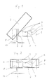
- Fig. 1 is a device for establishing a non-releasable connection shown between two optical fibers in the form of a fusion splice.
- a frame 1 with a U-shaped cross-section can be seen, on one of which the ends two optical fibers to be connected to each other at a joint aligned guide 2 is arranged.
- the guide 2 is in a recess 3 of the frame 1 and is provided with a groove 4 which is a V-shaped Cross-section and thus a reliable merge the ends of the optical fibers.
- the Electrodes 5 are on mutually opposite inner surfaces 6 in the region the recess 3 formed side walls of the frame 1.
- a hood 7 is through a pivot 8 between an open position and a pivoted position on the frame 1.
- the hood 7 shields in this first position at the same time the environment from heat, which during the formation of Melt splice is generated by the electrodes 5.
- Open position of the hood 7 is the frame 1 in the area of the joint exposed. In this position, optical fibers can be inserted into the guide 2 and align the mutually facing ends of the optical waveguides with one another.
- a switch 9 is open Hood 7 switched off and switched on when hood 7 is closed.
- the Switch 9 is connected to the hood 7 by a lever 10. This has to Consequence that the switch 9 when moving the hood 7 in the first is to be called closed position is also closed. That way through the Hood 7 operated switch 9 is used to start the splicing process automatically, that is, to position the individual fibers exactly, the electrodes 5 turn on and determine the splice loss when the hood 7 the first Has reached position.
- Switch 9 can also have a sensor-operated limit switch on frame 1 be provided, which determines the closed position of the hood 7 and then the splicing process starts.
- the splicing process then removes the hood 7 from each other connected optical fiber opened.
- the lever 10 By moving the hood 7 of the first position away in a second position is the lever 10 at the same time Switch 9 actuated, whereby the electrodes 5 are deactivated and the Splicing process is ended.
- the hood 7 can therefore be opened without danger run that about the operating personnel by the electrodes 5 during the Heat or the high electrical voltage is affected.
- a instead of the lever 10 sensor-operated limit switch is provided, which immediately Electrodes 5 turns off and the splicing process ends when the hood 7 leaves the first position and moves towards the closed position Position occupies a second position.
Landscapes
- Physics & Mathematics (AREA)
- Engineering & Computer Science (AREA)
- Plasma & Fusion (AREA)
- General Physics & Mathematics (AREA)
- Optics & Photonics (AREA)
- Mechanical Coupling Of Light Guides (AREA)
- Optical Couplings Of Light Guides (AREA)
Abstract
Description
- Fig. 1
- eine schematische Darstellung der erfindungsgemäßen Vorrichtung mit einer sich in einer geöffneten Stellung befindenden Haube und
- Fig. 2
- eine Darstellung gemäß Fig. 1 mit der sich in einer geschlossenen Stellung befindenden Haube.
- 1
- Gestell
- 2
- Führung
- 3
- Vertiefung
- 4
- Nut
- 5
- Elektrode
- 6
- Innenfläche
- 7
- Haube
- 8
- Drehgelenk
- 9
- Schalter
- 10
- Hebel
Claims (11)
- Vorrichtung zum Herstellen einer nichtlösbaren Verbindung zwischen wenigstens zwei Lichtwellenleitern, insbesondere eines Schmelzspleißes, mit einem Gestell (1), an dem eine die Enden wenigstens zweier miteinander zu verbindenden Lichtwellenleiter an einer Fügestelle zueinander ausrichtende Führung (2) und Mittel (5) zum Verbinden der Lichtwellenleiter im Bereich der Fügestelle angeordnet sind, und mit wenigstens einer bewegbar ausgebildeten Haube (7), mit der das Gestell (1) zumindest im Bereich der Fügestelle abdeckbar ist,
dadurch gekennzeichnet, daß ein durch die Haube (7) betätigbarer Schalter (9) vorgesehen ist, durch den die Mittel (5) zum Verbinden der Lichtwellenleiter derart schaltbar sind, daß sie in einer ersten Stellung der Haube (7) eingeschaltet und in einer zweiten Stellung der Haube (7) ausgeschaltet sind. - Vorrichtung nach Anspruch 1,
dadurch gekennzeichnet, daß das Gestell (1) in der ersten Stellung der Haube (7) durch diese zumindest im Bereich der Fügestelle abgedeckt ist. - Vorrichtung nach Anspruch 1 oder 2,
dadurch gekennzeichnet, daß der Schalter (9) mit einem die Stellung der Haube (7) detektierenden Sensor gekoppelt ist. - Vorrichtung nach einem der Ansprüche 1 bis 3,
dadurch gekennzeichnet, daß durch die Mittel (5) zum Verbinden der Lichtwellenleiter eine die Lichtwellenleiter miteinander verschweißende Wärme erzeugbar ist. - Vorrichtung nach Anspruch 4,
dadurch gekennzeichnet, daß die Mittel zum Verbinden der Lichtwellenleiter wenigstens zwei Elektroden (5) im Bereich der Fügestelle aufweisen, mit denen ein elektrischer Lichtbogen zum Verschweißen der Lichtwellenleiter erzeugbar ist. - Vorrichtung nach Anspruch 5,
dadurch gekennzeichnet, daß die Elektroden (5) beidseitig der Führung (2) angeordnet sind. - Vorrichtung nach einem der Ansprüche 1 bis 6,
dadurch gekennzeichnet, daß die Führung (2) mit wenigstens einer Nut (4), die vorzugsweise einen V-förmigen Querschnitt aufweist, versehen oder als 3-Punkt-Lagerung ausgebildet ist. - Vorrichtung nach einem der Ansprüche 1 bis 7,
dadurch gekennzeichnet, daß die Haube (7) verschwenkbar an dem Gestell (1) angeordnet ist. - Vorrichtung nach Anspruch 8
dadurch gekennzeichnet, daß die Haube (7) und der Schalter (9) durch ein mechanisches Gestänge, vorzugsweise einen Hebel (10), miteinander gekoppelt sind. - Vorrichtung nach einem der Ansprüche 1 bis 9,
gekennzeichnet durch Mittel zum Aufheben der Funktion des Schalters (9). - Vorrichtung nach Anspruch 10
dadurch gekennzeichnet, daß die Mittel zum Aufheben der Funktion des Schalters (9) eine manuell zu betätigende Taste aufweisen.
Priority Applications (1)
| Application Number | Priority Date | Filing Date | Title |
|---|---|---|---|
| DE20122133U DE20122133U1 (de) | 2001-01-09 | 2001-11-06 | Vorrichtung zum Herstellen einer nichtlösbaren Verbindung zwischen wenigstens zwei Lichtwellenleitern, insbesondere eines Schmelzspleißes |
Applications Claiming Priority (2)
| Application Number | Priority Date | Filing Date | Title |
|---|---|---|---|
| DE10100566A DE10100566A1 (de) | 2001-01-09 | 2001-01-09 | Vorrichtung zum Herstellen einer nichtlösbaren Verbindung zwischen wenigstens zwei Lichtwellenleitern, insbesondere eines Schmelzspleißes |
| DE10100566 | 2001-01-09 |
Publications (3)
| Publication Number | Publication Date |
|---|---|
| EP1223441A2 true EP1223441A2 (de) | 2002-07-17 |
| EP1223441A3 EP1223441A3 (de) | 2003-07-23 |
| EP1223441B1 EP1223441B1 (de) | 2005-04-06 |
Family
ID=7669976
Family Applications (1)
| Application Number | Title | Priority Date | Filing Date |
|---|---|---|---|
| EP01126252A Expired - Lifetime EP1223441B1 (de) | 2001-01-09 | 2001-11-06 | Vorrichtung zum Herstellen einer nicht lösbaren Verbindung zwischen wenigstens zwei Lichtwellenleitern, insbesondere eines Schmelzspleisses |
Country Status (3)
| Country | Link |
|---|---|
| EP (1) | EP1223441B1 (de) |
| AT (1) | ATE292809T1 (de) |
| DE (2) | DE10100566A1 (de) |
Family Cites Families (2)
| Publication number | Priority date | Publication date | Assignee | Title |
|---|---|---|---|---|
| US5002351A (en) * | 1988-07-05 | 1991-03-26 | Preformed Line Products Company | Fusion splicer for optical fibers |
| US5524163A (en) * | 1994-12-29 | 1996-06-04 | Sumitomo Electric Industries, Ltd. | Apparatus for splicing optical fibers and method for the same |
-
2001
- 2001-01-09 DE DE10100566A patent/DE10100566A1/de not_active Withdrawn
- 2001-11-06 DE DE50105826T patent/DE50105826D1/de not_active Expired - Lifetime
- 2001-11-06 EP EP01126252A patent/EP1223441B1/de not_active Expired - Lifetime
- 2001-11-06 AT AT01126252T patent/ATE292809T1/de not_active IP Right Cessation
Also Published As
| Publication number | Publication date |
|---|---|
| EP1223441A3 (de) | 2003-07-23 |
| EP1223441B1 (de) | 2005-04-06 |
| DE10100566A1 (de) | 2002-07-11 |
| DE50105826D1 (de) | 2005-05-12 |
| ATE292809T1 (de) | 2005-04-15 |
Similar Documents
| Publication | Publication Date | Title |
|---|---|---|
| DE69925152T2 (de) | Benutzung eines Lasers zum Fusionsspleißen optischer Komponenten mit sehr unterschiedlichem Querschnitt | |
| DE3544136C2 (de) | ||
| DE69015927T2 (de) | Vorrichtung und Verfahren für die Herstellung von permanenten faseroptischen Spleissen niedriger Dämpfung. | |
| DE69030077T2 (de) | Methode zur Herstellung einer eine reflexionsarme faseroptische Verbindung enthaltenden optischen Vorrichtung | |
| DE3828604A1 (de) | Verfahren und einrichtung zur messung der optischen daempfung eines optischen mediums | |
| EP0216211A2 (de) | Wellenlängenmultiplex-Komponente für ein optisches Netz mit Monomode-Übertragsfaser | |
| DE3334565A1 (de) | Vorrichtung zur herstellung von einschnuerungen in fasern | |
| DE69111954T2 (de) | Identifiziereinrichtung für optische Fasern. | |
| DE3630163A1 (de) | Zentriervorrichung zum zentrieren von lichtleiter-fasern waehrend des schweissens | |
| DE3036618A1 (de) | Steuerelement zum steuern einer lichtuebertragung zwischen lichtwellenleitern | |
| DE60127757T2 (de) | Verfahren zum Verspleissen von Glasfasern | |
| DE20122133U1 (de) | Vorrichtung zum Herstellen einer nichtlösbaren Verbindung zwischen wenigstens zwei Lichtwellenleitern, insbesondere eines Schmelzspleißes | |
| EP1223441A2 (de) | Vorrichtung zum Herstellen einer nicht lösbaren Verbindung zwischen wenigstens zwei Lichtwellenleitern, insbesondere eines Schmelzspleisses | |
| DE3105748C2 (de) | Verfahren zur Herstellung eines Lichtwellenleiter-Kopplers | |
| DE2626839C2 (de) | Verfahren zum Justieren von optischen Bauteilen beim Koppeln und Spleißen | |
| DE69416714T2 (de) | Verfahren zum thermischen Verspleissen von optischen Fasern | |
| DE2708014C3 (de) | Stecker zur Ankopplung eines Einzellichtwellenleiters an einen anderen Einzellichtwellenleiter oder an einen Lichtsender oder Lichtempfänger | |
| EP1381895A2 (de) | Bearbeiten einer isolierten optischen faser | |
| DE4236806A1 (de) | Optisches Dämpfungsglied, Verfahren zu seiner Herstellung und ein hierzu geeigentes thermisches Spleißgerät | |
| DE3411595C2 (de) | ||
| DE19911981B4 (de) | Verfahren zur Endflächenbearbeitung von Kunststoff-Lichtwellenleitern | |
| DE69330102T2 (de) | Faseroptischer abschluss | |
| DE19512110C2 (de) | Anschlußklemme für ein Lichtwellenleiterkabel | |
| DE69409867T2 (de) | Vorrichtung zum Verbinden einer F-dotierten Monomodefaser mit einer SiO2 Monomodefaser | |
| EP1022593A1 (de) | Verfahren zur Konfektionierung eines Lichtleiters |
Legal Events
| Date | Code | Title | Description |
|---|---|---|---|
| PUAI | Public reference made under article 153(3) epc to a published international application that has entered the european phase |
Free format text: ORIGINAL CODE: 0009012 |
|
| AK | Designated contracting states |
Kind code of ref document: A2 Designated state(s): AT BE CH CY DE DK ES FI FR GB GR IE IT LI LU MC NL PT SE TR |
|
| AX | Request for extension of the european patent |
Free format text: AL;LT;LV;MK;RO;SI |
|
| PUAL | Search report despatched |
Free format text: ORIGINAL CODE: 0009013 |
|
| AK | Designated contracting states |
Designated state(s): AT BE CH CY DE DK ES FI FR GB GR IE IT LI LU MC NL PT SE TR |
|
| AX | Request for extension of the european patent |
Extension state: AL LT LV MK RO SI |
|
| 17P | Request for examination filed |
Effective date: 20040122 |
|
| 17Q | First examination report despatched |
Effective date: 20040301 |
|
| AKX | Designation fees paid |
Designated state(s): AT BE CH CY DE DK ES FI FR GB GR IE IT LI LU MC NL PT SE TR |
|
| GRAP | Despatch of communication of intention to grant a patent |
Free format text: ORIGINAL CODE: EPIDOSNIGR1 |
|
| GRAS | Grant fee paid |
Free format text: ORIGINAL CODE: EPIDOSNIGR3 |
|
| GRAA | (expected) grant |
Free format text: ORIGINAL CODE: 0009210 |
|
| RTI1 | Title (correction) |
Free format text: APPARATUS TO PRODUCE A NON RELEASABLE CONNECTION BETWEEN AT LEAST TWO OPTICAL WAVEGUIDES, IN PARTICULAR OF A FUSION SPLIC |
|
| AK | Designated contracting states |
Kind code of ref document: B1 Designated state(s): AT BE CH CY DE DK ES FI FR GB GR IE IT LI LU MC NL PT SE TR |
|
| PG25 | Lapsed in a contracting state [announced via postgrant information from national office to epo] |
Ref country code: IT Free format text: LAPSE BECAUSE OF FAILURE TO SUBMIT A TRANSLATION OF THE DESCRIPTION OR TO PAY THE FEE WITHIN THE PRESCRIBED TIME-LIMIT;WARNING: LAPSES OF ITALIAN PATENTS WITH EFFECTIVE DATE BEFORE 2007 MAY HAVE OCCURRED AT ANY TIME BEFORE 2007. THE CORRECT EFFECTIVE DATE MAY BE DIFFERENT FROM THE ONE RECORDED. Effective date: 20050406 Ref country code: IE Free format text: LAPSE BECAUSE OF FAILURE TO SUBMIT A TRANSLATION OF THE DESCRIPTION OR TO PAY THE FEE WITHIN THE PRESCRIBED TIME-LIMIT Effective date: 20050406 Ref country code: TR Free format text: LAPSE BECAUSE OF FAILURE TO SUBMIT A TRANSLATION OF THE DESCRIPTION OR TO PAY THE FEE WITHIN THE PRESCRIBED TIME-LIMIT Effective date: 20050406 Ref country code: FI Free format text: LAPSE BECAUSE OF FAILURE TO SUBMIT A TRANSLATION OF THE DESCRIPTION OR TO PAY THE FEE WITHIN THE PRESCRIBED TIME-LIMIT Effective date: 20050406 Ref country code: NL Free format text: LAPSE BECAUSE OF FAILURE TO SUBMIT A TRANSLATION OF THE DESCRIPTION OR TO PAY THE FEE WITHIN THE PRESCRIBED TIME-LIMIT Effective date: 20050406 |
|
| REG | Reference to a national code |
Ref country code: GB Ref legal event code: FG4D Free format text: NOT ENGLISH |
|
| REG | Reference to a national code |
Ref country code: CH Ref legal event code: EP |
|
| REG | Reference to a national code |
Ref country code: IE Ref legal event code: FG4D Free format text: LANGUAGE OF EP DOCUMENT: GERMAN |
|
| REF | Corresponds to: |
Ref document number: 50105826 Country of ref document: DE Date of ref document: 20050512 Kind code of ref document: P |
|
| PG25 | Lapsed in a contracting state [announced via postgrant information from national office to epo] |
Ref country code: GR Free format text: LAPSE BECAUSE OF FAILURE TO SUBMIT A TRANSLATION OF THE DESCRIPTION OR TO PAY THE FEE WITHIN THE PRESCRIBED TIME-LIMIT Effective date: 20050706 Ref country code: DK Free format text: LAPSE BECAUSE OF FAILURE TO SUBMIT A TRANSLATION OF THE DESCRIPTION OR TO PAY THE FEE WITHIN THE PRESCRIBED TIME-LIMIT Effective date: 20050706 |
|
| PG25 | Lapsed in a contracting state [announced via postgrant information from national office to epo] |
Ref country code: ES Free format text: LAPSE BECAUSE OF FAILURE TO SUBMIT A TRANSLATION OF THE DESCRIPTION OR TO PAY THE FEE WITHIN THE PRESCRIBED TIME-LIMIT Effective date: 20050717 |
|
| REG | Reference to a national code |
Ref country code: SE Ref legal event code: TRGR |
|
| PG25 | Lapsed in a contracting state [announced via postgrant information from national office to epo] |
Ref country code: PT Free format text: LAPSE BECAUSE OF FAILURE TO SUBMIT A TRANSLATION OF THE DESCRIPTION OR TO PAY THE FEE WITHIN THE PRESCRIBED TIME-LIMIT Effective date: 20050908 |
|
| NLV1 | Nl: lapsed or annulled due to failure to fulfill the requirements of art. 29p and 29m of the patents act | ||
| GBT | Gb: translation of ep patent filed (gb section 77(6)(a)/1977) |
Effective date: 20050914 |
|
| PG25 | Lapsed in a contracting state [announced via postgrant information from national office to epo] |
Ref country code: CY Free format text: LAPSE BECAUSE OF FAILURE TO SUBMIT A TRANSLATION OF THE DESCRIPTION OR TO PAY THE FEE WITHIN THE PRESCRIBED TIME-LIMIT Effective date: 20051106 Ref country code: AT Free format text: LAPSE BECAUSE OF NON-PAYMENT OF DUE FEES Effective date: 20051106 |
|
| PG25 | Lapsed in a contracting state [announced via postgrant information from national office to epo] |
Ref country code: CH Free format text: LAPSE BECAUSE OF NON-PAYMENT OF DUE FEES Effective date: 20051130 Ref country code: LI Free format text: LAPSE BECAUSE OF NON-PAYMENT OF DUE FEES Effective date: 20051130 Ref country code: MC Free format text: LAPSE BECAUSE OF NON-PAYMENT OF DUE FEES Effective date: 20051130 Ref country code: LU Free format text: LAPSE BECAUSE OF NON-PAYMENT OF DUE FEES Effective date: 20051130 Ref country code: BE Free format text: LAPSE BECAUSE OF NON-PAYMENT OF DUE FEES Effective date: 20051130 |
|
| REG | Reference to a national code |
Ref country code: IE Ref legal event code: FD4D |
|
| PLBE | No opposition filed within time limit |
Free format text: ORIGINAL CODE: 0009261 |
|
| STAA | Information on the status of an ep patent application or granted ep patent |
Free format text: STATUS: NO OPPOSITION FILED WITHIN TIME LIMIT |
|
| ET | Fr: translation filed | ||
| 26N | No opposition filed |
Effective date: 20060110 |
|
| REG | Reference to a national code |
Ref country code: CH Ref legal event code: PL |
|
| BERE | Be: lapsed |
Owner name: CCS TECHNOLOGY, INC. Effective date: 20051130 |
|
| PGFP | Annual fee paid to national office [announced via postgrant information from national office to epo] |
Ref country code: SE Payment date: 20071128 Year of fee payment: 7 |
|
| EUG | Se: european patent has lapsed | ||
| PG25 | Lapsed in a contracting state [announced via postgrant information from national office to epo] |
Ref country code: SE Free format text: LAPSE BECAUSE OF NON-PAYMENT OF DUE FEES Effective date: 20081107 |
|
| PGFP | Annual fee paid to national office [announced via postgrant information from national office to epo] |
Ref country code: FR Payment date: 20101202 Year of fee payment: 10 |
|
| PGFP | Annual fee paid to national office [announced via postgrant information from national office to epo] |
Ref country code: DE Payment date: 20101126 Year of fee payment: 10 |
|
| PGFP | Annual fee paid to national office [announced via postgrant information from national office to epo] |
Ref country code: GB Payment date: 20101124 Year of fee payment: 10 |
|
| GBPC | Gb: european patent ceased through non-payment of renewal fee |
Effective date: 20111106 |
|
| REG | Reference to a national code |
Ref country code: FR Ref legal event code: ST Effective date: 20120731 |
|
| PG25 | Lapsed in a contracting state [announced via postgrant information from national office to epo] |
Ref country code: GB Free format text: LAPSE BECAUSE OF NON-PAYMENT OF DUE FEES Effective date: 20111106 |
|
| PG25 | Lapsed in a contracting state [announced via postgrant information from national office to epo] |
Ref country code: FR Free format text: LAPSE BECAUSE OF NON-PAYMENT OF DUE FEES Effective date: 20111130 |
|
| REG | Reference to a national code |
Ref country code: DE Ref legal event code: R119 Ref document number: 50105826 Country of ref document: DE Effective date: 20130601 |
|
| PG25 | Lapsed in a contracting state [announced via postgrant information from national office to epo] |
Ref country code: DE Free format text: LAPSE BECAUSE OF NON-PAYMENT OF DUE FEES Effective date: 20130601 |