EP1223441A2 - Apparatus to produce a non releasable connection between at least two light guide, in particular of a fusion splice - Google Patents
Apparatus to produce a non releasable connection between at least two light guide, in particular of a fusion splice Download PDFInfo
- Publication number
- EP1223441A2 EP1223441A2 EP01126252A EP01126252A EP1223441A2 EP 1223441 A2 EP1223441 A2 EP 1223441A2 EP 01126252 A EP01126252 A EP 01126252A EP 01126252 A EP01126252 A EP 01126252A EP 1223441 A2 EP1223441 A2 EP 1223441A2
- Authority
- EP
- European Patent Office
- Prior art keywords
- hood
- switch
- joint
- optical fibers
- frame
- Prior art date
- Legal status (The legal status is an assumption and is not a legal conclusion. Google has not performed a legal analysis and makes no representation as to the accuracy of the status listed.)
- Granted
Links
Images
Classifications
-
- G—PHYSICS
- G02—OPTICS
- G02B—OPTICAL ELEMENTS, SYSTEMS OR APPARATUS
- G02B6/00—Light guides; Structural details of arrangements comprising light guides and other optical elements, e.g. couplings
- G02B6/24—Coupling light guides
- G02B6/255—Splicing of light guides, e.g. by fusion or bonding
- G02B6/2551—Splicing of light guides, e.g. by fusion or bonding using thermal methods, e.g. fusion welding by arc discharge, laser beam, plasma torch
Definitions
- the invention relates to a device for producing a non-detachable Connection between at least two optical fibers, in particular one Fusion splice, with a frame on which the ends of at least two optical fibers to be connected to one another at a joint aligning guide and means for connecting the optical fibers in the area the joint are arranged, and with at least one movable Hood with which the frame can be covered at least in the area of the joint.
- Optical fibers are increasingly used for the transmission of data used.
- Optical fibers are largely insensitive to electromagnetic Disruptions and are also characterized by very high transmission rates of up to to several Gbit / s.
- optical fibers are also cheaper to manufacture, largely bug-proof and without complex protective measures also for suitable for explosive environments.
- Data that were previously available as an electrical signal are used for the Transmission by means of an optical fiber through an optical transmitter, for example a laser or a light-emitting diode, converted into an optical signal, which in the optical fiber is coupled.
- an optical transmitter for example a laser or a light-emitting diode
- modulated light beam takes its way through the optical fiber by turning on the interface between an inner core glass and this one concentrically surrounding cladding glass with a lower optical density total is reflected.
- the prerequisite for this is that the light beam is below a certain angle, the acceptance angle, coupled into the optical waveguide becomes. Due to this total reflection, the light beam also follows curvatures of the Optical waveguide.
- a receiver for example a photodiode or a phototransistor, again in an electrical one Signal converted.
- the Optical fibers in single-mode fibers (single-mode fibers) and multimode fibers divide.
- the core glass has a diameter of Order of magnitude of the wavelength of light, so that there is only one fashion in Core glass can spread, depending on the quality of an optical transmitter this also has a spectral width.
- Wear with multimode fibers several discrete modes, which are mainly in the field distribution and the distinguish wavelength-dependent propagation speed, for Signal transmission at.
- the multimode fibers can be divided into stepped profile fibers in which core glass and Cladding glass have a constant refractive index, and gradient profile fibers where the refractive index of the core glass decreases parabolically towards the cladding glass, divide.
- mode dispersion usually lead together with a chromatic dispersion limits the bandwidth of the optical fiber.
- the transmission capacity of an optical fiber is in addition to that through Dispersion influenced bandwidth mainly by the wavelength-dependent attenuation, i.e. the energy loss of the light beam marked in the course of a transmission link.
- Cause of the Damping can be numerous influencing factors, for example fault points such as such as air bubbles, inclusions, micro cracks or inhomogeneities Cause absorption and scattering of the light beam.
- fault points such as air bubbles, inclusions, micro cracks or inhomogeneities
- absorption and scattering of the light beam Especially with the Connecting two optical fibers can cause errors, such as through Reflections at the fiber-air interface, Fresnel losses occurring, occur that cause high damping.
- Known devices for making a non-releasable connection one end of two optical fibers between two optical fibers a joint aligning guide and means for connecting the Optical fibers in the area of this joint.
- the joint is covered by a hood covered.
- the splice is then formed on the joint attached hood instead and is usually by manual operation of a Button triggered after the hood had been put on by a sensor the joint has been determined.
- Optical fiber cables are usually with a between a sheath and the provided individual optical fibers existing gel-like filling compound, which at Preparing the ends of the optical fibers to be connected, for example if the cable sheath is unavoidably removed and can stick to the hands of a mechanic, causing them to press the button is transmitted and dirty.
- the invention has for its object to develop a device for establishing a non-releasable connection between at least two optical fibers in such a way that a comparatively simple and fast operation can be achieved.
- the frame is expediently in the first position of the hood covered at least in the area of the joint.
- the means for connecting the optical fibers have at least two electrodes in the area of the joint, with which an electric arc for welding the optical fibers can be generated.
- This so-called arc splicing technology enables on reliable way of welding the optical fibers in the electrical Arc at temperatures of around 2000 ° K. This is an advantage Connection also to arrange the electrodes on both sides of the guide, see above that a simple and, above all, maintenance-friendly arrangement is guaranteed.
- the leadership at least one groove, which preferably has a V-shaped cross section, provided or designed as a 3-point bearing.
- the Hood pivotally arranged on the frame. This way a pivoting movement of the hood between its open and closed position, through which a constructively simple manner Actuation of the switch can be realized.
- the hood is advantageous for this and the switch by a mechanical linkage, preferably a lever, coupled with each other, so that it is economically economical Design results.
- means for Unlocking the switch proposed to a specific Adaptation of the device to operational requirements or personnel To enable peculiarities.
- the means to remove the function of Switch have a manually operated button.
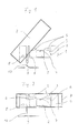
- Fig. 1 is a device for establishing a non-releasable connection shown between two optical fibers in the form of a fusion splice.
- a frame 1 with a U-shaped cross-section can be seen, on one of which the ends two optical fibers to be connected to each other at a joint aligned guide 2 is arranged.
- the guide 2 is in a recess 3 of the frame 1 and is provided with a groove 4 which is a V-shaped Cross-section and thus a reliable merge the ends of the optical fibers.
- the Electrodes 5 are on mutually opposite inner surfaces 6 in the region the recess 3 formed side walls of the frame 1.
- a hood 7 is through a pivot 8 between an open position and a pivoted position on the frame 1.
- the hood 7 shields in this first position at the same time the environment from heat, which during the formation of Melt splice is generated by the electrodes 5.
- Open position of the hood 7 is the frame 1 in the area of the joint exposed. In this position, optical fibers can be inserted into the guide 2 and align the mutually facing ends of the optical waveguides with one another.
- a switch 9 is open Hood 7 switched off and switched on when hood 7 is closed.
- the Switch 9 is connected to the hood 7 by a lever 10. This has to Consequence that the switch 9 when moving the hood 7 in the first is to be called closed position is also closed. That way through the Hood 7 operated switch 9 is used to start the splicing process automatically, that is, to position the individual fibers exactly, the electrodes 5 turn on and determine the splice loss when the hood 7 the first Has reached position.
- Switch 9 can also have a sensor-operated limit switch on frame 1 be provided, which determines the closed position of the hood 7 and then the splicing process starts.
- the splicing process then removes the hood 7 from each other connected optical fiber opened.
- the lever 10 By moving the hood 7 of the first position away in a second position is the lever 10 at the same time Switch 9 actuated, whereby the electrodes 5 are deactivated and the Splicing process is ended.
- the hood 7 can therefore be opened without danger run that about the operating personnel by the electrodes 5 during the Heat or the high electrical voltage is affected.
- a instead of the lever 10 sensor-operated limit switch is provided, which immediately Electrodes 5 turns off and the splicing process ends when the hood 7 leaves the first position and moves towards the closed position Position occupies a second position.
Abstract
Description
Die Erfindung betrifft eine Vorrichtung zum Herstellen einer nichtlösbaren Verbindung zwischen wenigstens zwei Lichtwellenleitern, insbesondere eines Schmelzspleißes, mit einem Gestell, an dem eine die Enden wenigstens zweier miteinander zu verbindenden Lichtwellenleiter an einer Fügestelle zueinander ausrichtende Führung und Mittel zum Verbinden der Lichtwellenleiter im Bereich der Fügestelle angeordnet sind, und mit wenigstens einer bewegbar ausgebildeten Haube, mit der das Gestell zumindest im Bereich der Fügestelle abdeckbar ist.The invention relates to a device for producing a non-detachable Connection between at least two optical fibers, in particular one Fusion splice, with a frame on which the ends of at least two optical fibers to be connected to one another at a joint aligning guide and means for connecting the optical fibers in the area the joint are arranged, and with at least one movable Hood with which the frame can be covered at least in the area of the joint.
Für die Übertragung von Daten werden zunehmend Lichtwellenleiter (LWL) eingesetzt. Die in der Regel aus Glasfaser oder Kunststoff bestehenden Lichtwellenleiter sind weitgehend unempfindlich gegenüber elektromagnetischen Störungen und zeichnen sich zudem durch sehr hohe Übertragungsraten von bis zu mehreren Gbit/s aus. Im Vergleich mit etwa herkömmlichen Kupferleitungen sind Lichtwellenleiter darüber hinaus kostengünstiger herzustellen, weitgehend abhörsicher und ohne aufwendige Schutzmaßnahmen auch für explosionsgefährdete Umgebungen geeignet.Optical fibers are increasingly used for the transmission of data used. The usually made of fiberglass or plastic Optical fibers are largely insensitive to electromagnetic Disruptions and are also characterized by very high transmission rates of up to to several Gbit / s. In comparison with conventional copper lines optical fibers are also cheaper to manufacture, largely bug-proof and without complex protective measures also for suitable for explosive environments.
Daten, die bislang in der Regel als elektrisches Signal vorliegen, werden für die Übertragung mittels eines Lichtwellenleiters durch einen optischen Sender, etwa eine Laser- oder eine Leuchtdiode, in ein optisches Signal umgewandelt, das in den Lichtwellenleiter eingekoppelt wird. Ein so mit den zu übertragenden Daten modulierter Lichtstrahl nimmt seinen Weg durch den Lichtwellenleiter, indem er an der Grenzfläche zwischen einem inneren Kernglas und einem dieses konzentrisch umgebenden, mit einer niedrigeren optischen Dichte versehenen Mantelglas total reflektiert wird. Voraussetzung hierfür ist, daß der Lichtstrahl unterhalb eines bestimmten Winkels, dem Akzeptanzwinkel, in den Lichtwellenleiter eingekoppelt wird. Der Lichtstrahl folgt durch diese Totalreflexion auch Krümmungen des Lichtwellenleiters. Im Anschluß an die Übertragung des optischen Signals durch den Lichtwellenleiter wird dieses zur Weiterverarbeitung mittels eines Empfängers, beispielsweise eine Fotodiode oder ein Fototransistor, wieder in ein elektrisches Signal umgewandelt.Data that were previously available as an electrical signal are used for the Transmission by means of an optical fiber through an optical transmitter, for example a laser or a light-emitting diode, converted into an optical signal, which in the optical fiber is coupled. So with the data to be transferred modulated light beam takes its way through the optical fiber by turning on the interface between an inner core glass and this one concentrically surrounding cladding glass with a lower optical density total is reflected. The prerequisite for this is that the light beam is below a certain angle, the acceptance angle, coupled into the optical waveguide becomes. Due to this total reflection, the light beam also follows curvatures of the Optical waveguide. Following the transmission of the optical signal through the optical fiber is used for further processing by means of a receiver, for example a photodiode or a phototransistor, again in an electrical one Signal converted.
Nach der Art der Führung eines Lichtstrahls im Kernglas lassen sich die Lichtwellenleiter in Singlemodefasern (Einmodenfaser) und Multimodefasern unterteilen. Bei Singlemodefasern liegt der Durchmesser des Kernglas in der Größenordnung der Wellenlänge des Lichts, so daß sich nur eine einzige Mode im Kernglas ausbreiten kann, wobei bedingt durch die Güte eines optischen Sender auch diese eine spektrale Breite aufweist. Bei Multimodefasern hingegen tragen mehrere diskrete Moden, die sich vornehmlich in der Feldverteilung und der wellenlängenabhängigen Ausbreitungsgeschwindigkeit unterscheiden, zur Signalübertragung bei. Je nach Art der Ausgestaltung der Brechzahl des Kernglas lassen sich die Multimodefasern in Stufenprofilfasern, bei denen Kernglas und Mantelglas eine konstante Brechzahl aufweisen, und Gradientenprofilfasern, bei denen die Brechzahl des Kernglas zu dem Mantelglas hin parabelförmig abnimmt, unterteilen. Insbesondere bei Stufenprofilfasern ergeben sich Laufzeitunterschiede der einzelnen Moden, die zu einer Verbreiterung des Lichtimpulses, die sogenannte Modendispersion, führen, die meist zusammen mit einer chromatischen Dispersion die Bandbreite des Lichtwellenleiters beschränkt.According to the way a light beam is guided in the core glass, the Optical fibers in single-mode fibers (single-mode fibers) and multimode fibers divide. In the case of single-mode fibers, the core glass has a diameter of Order of magnitude of the wavelength of light, so that there is only one fashion in Core glass can spread, depending on the quality of an optical transmitter this also has a spectral width. Wear with multimode fibers several discrete modes, which are mainly in the field distribution and the distinguish wavelength-dependent propagation speed, for Signal transmission at. Depending on the type of refractive index of the core glass The multimode fibers can be divided into stepped profile fibers in which core glass and Cladding glass have a constant refractive index, and gradient profile fibers where the refractive index of the core glass decreases parabolically towards the cladding glass, divide. There are differences in transit time, particularly with step profile fibers of the individual modes that lead to a broadening of the light pulse, the so-called mode dispersion, usually lead together with a chromatic dispersion limits the bandwidth of the optical fiber.
Das Übertragungsvermögen eines Lichtwellenleiters ist neben der durch die Dispersion beeinflußten Bandbreite hauptsächlich durch die wellenlängenabhängige Dämpfung, das heißt den Energieverlust des Lichtstrahls im Verlauf einer Übertragungsstrecke gekennzeichnet. Ursächlich für die Dämpfung können zahlreiche Einflußfaktoren sein, zum Beispiel Fehlerstellen wie etwa Luftblasen, Einschlüsse, Mikrorisse oder Inhomogenitäten, die eine Absorption und Streuung des Lichtstrahls hervorrufen. Vor allem bei der Verbindung zweier Lichtwellenleiter können Fehler, wie beispielsweise durch Reflexionen an der Grenzfläche Lichtwellenleiter-Luft auftretende Fresnelverluste, vorkommen, die eine hohe Dämpfung verursachen.The transmission capacity of an optical fiber is in addition to that through Dispersion influenced bandwidth mainly by the wavelength-dependent attenuation, i.e. the energy loss of the light beam marked in the course of a transmission link. Cause of the Damping can be numerous influencing factors, for example fault points such as such as air bubbles, inclusions, micro cracks or inhomogeneities Cause absorption and scattering of the light beam. Especially with the Connecting two optical fibers can cause errors, such as through Reflections at the fiber-air interface, Fresnel losses occurring, occur that cause high damping.
Um dies zu vermeiden sind die üblicherweise zur Verbindung zweier Lichtwellenleiter verwendeten Steckverbinder aufwendig ausgestaltet. Bei einfachen Anwendungen, zum Beispiel dem Aneinanderreihen von Lichtwellenleiter für die Bildung langer Leitungen oder dem Reparieren von Kabelbrüchen, finden daher häufig Spleiße Anwendung, bei denen es sich um nichtlösbare Verbindungen zwischen zwei Lichtwellenleitern handelt. Die sich durch eine geringe Dämpfung auszeichnenden Spleiße können als mechanischer beziehungsweise Crimpspleiß, als Klebespleiß oder als Schmelzbeziehungsweise Fusionsspleiß ausgebildet sein.To avoid this, they are usually used to connect two Fiber optic connector used complex designed. at simple applications, for example stringing together Optical fibers for the formation of long lines or the repair of Broken cables, therefore, often find splices that are used non-detachable connections between two optical fibers. Which due to a low attenuation splices can be considered mechanical or crimp splice, as an adhesive splice or as a fusion or splicing method Fusion splice be formed.
Beim mechanischen Spleiß werden die Enden zweier Lichtwellenleiter durch Pressen oder Crimpen zusammengehalten, wohingegen beim Klebespleiß an der Fügestelle zwischen den sich gegenüberliegenden Enden zweier Lichtwellenleiter ein Klebstoff eingeführt wird, dessen Brechungsindex dem des Kernglases der Lichtwellenleiter entspricht. Der mechanische Spleiß und der Klebespleiß haben vergleichbare Dämpfungswerte und können mühelos vor Ort angewandt werden. Nicht zuletzt aufgrund seiner geringen Dämpfungswerte ist der Schmelz- oder Fusionsspleiß, bei dem die Enden zweier Lichtwellenleiter oder Lichtwellenleitergruppen zueinander ausgerichtet und durch Erwärmen miteinander verschweißt werden, weit verbreitet. Als Wärmequellen werden in der Praxis vor allem eine Wasserstofflamme, eine Funkenstrecke oder ein Laser eingesetzt.With mechanical splices, the ends of two optical fibers are cut through Pressing or crimping held together, whereas the adhesive splice on the Joining point between the opposite ends of two optical fibers an adhesive is introduced whose refractive index is that of the core glass Optical fiber corresponds. Have the mechanical splice and the adhesive splice comparable damping values and can be easily applied on site. Not least because of its low damping values, the melting or Fusion splice, in which the ends of two optical fibers or Optical fiber groups aligned to each other and by heating are welded together, widely used. As heat sources in the Practice above all a hydrogen flame, a spark gap or a laser used.
Bekannte Vorrichtungen für die Herstellung einer nichtlösbaren Verbindung zwischen zwei Lichtwellenleitern weisen eine die Enden zweier Lichtwellenleiter an einer Fügestelle zueinander ausrichtende Führung und Mittel zum Verbinden der Lichtwellenleiter im Bereich dieser Fügestelle auf. Um während des Verbindens einerseits das Bedienpersonal zu schützen, beispielsweise vor einer beim Schmelzsspleiß eingesetzten Wärmequelle, und andererseits die exakt zueinander zu positionierenden Lichtwellenleiter gegen äußere Einflüsse, wie etwa Wind, Staub oder Erschütterungen, abzuschirmen, wird die Fügestelle durch eine Haube abgedeckt. Die Bildung des Spleißes findet dann bei auf die Fügestelle aufgesetzter Haube statt und wird gewöhnlich durch die manuelle Betätigung einer Taste ausgelöst, nachdem zuvor durch einen Sensor das Aufsetzen der Haube auf der Fügestelle festgestellt worden ist.Known devices for making a non-releasable connection one end of two optical fibers between two optical fibers a joint aligning guide and means for connecting the Optical fibers in the area of this joint. To while connecting on the one hand to protect the operating personnel, for example from an operator Melt splice used heat source, and on the other hand the exactly to each other optical fibers to be positioned against external influences, such as wind, To shield dust or vibrations, the joint is covered by a hood covered. The splice is then formed on the joint attached hood instead and is usually by manual operation of a Button triggered after the hood had been put on by a sensor the joint has been determined.
Insbesondere bei dem Einsatz einer solchen Vorrichtung für die Massenfertigung von durch Spleiße miteinander verbundenen Lichtwellenleiter hat sich die jeweilige manuelle Betätigung der Taste als störend herausgestellt. Grund hierfür ist, daß zum einen sich durch die häufige Betätigung die Verschleißanfälligkeit erhöht und zum anderen ein in der Summe nicht vernachlässigbarer, die Produktivität beeinträchtigender Zeitverlust entsteht. Ein weiterer Nachteil besteht darin, daß die Bedienung einer solchen Vorrichtung in ergonomischer Hinsicht ungünstig und für eine Automatisierung nicht besonders geeignet ist. Darüber hinaus ist die manuelle Betätigung der Taste mit einer unansehnlichen Verschmutzung der Vorrichtung verbunden. Denn häufig als Bündelader oder Hohlader ausgebildeten Lichtwellenleiterkabel sind in der Regel mit einem zwischen einer Hülle und den einzelnen Lichtwellenleitern vorhandenen gelartigen Füllmasse versehen, die beim Vorbereiten der Enden der miteinander zu verbindenden Lichtwellenleiter, beispielsweise bei einem unvermeidlichen Entfernen des Kabelmantels, austreten und an den Händen eines Monteurs haften kann, wodurch sie auf die Taste übertragen wird und diese verschmutzt.Especially when using such a device for mass production of optical fibers connected by splices, the respective manual actuation of the button turned out to be disturbing. The reason for this is that on the one hand, the susceptibility to wear increases due to frequent operation and on the other hand, productivity is not negligible overall impairing loss of time arises. Another disadvantage is that the Operation of such a device is ergonomically unfavorable and for automation is not particularly suitable. In addition, the manual operation of the button with an unsightly pollution of the Device connected. Because often trained as loose tube or tube Optical fiber cables are usually with a between a sheath and the provided individual optical fibers existing gel-like filling compound, which at Preparing the ends of the optical fibers to be connected, for example if the cable sheath is unavoidably removed and can stick to the hands of a mechanic, causing them to press the button is transmitted and dirty.
Der Erfindung liegt die Aufgabe zugrunde, eine Vorrichtung zum Herstellen einer nichtlösbaren Verbindung zwischen wenigstens zwei Lichtwellenleitern dahingehend weiterzubilden, daß sich eine vergleichsweise einfache und schnelle Bedienung erzielen läßt.The invention has for its object to develop a device for establishing a non-releasable connection between at least two optical fibers in such a way that a comparatively simple and fast operation can be achieved.
Diese Aufgabe ist bei einer Vorrichtung mit den eingangs genannten Merkmalen erfindungsgemäß dadurch gelöst, daß ein durch die Haube betätigbarer Schalter vorgesehen ist, durch den die Mittel zum Verbinden der Lichtwellenleiter derart schaltbar sind, daß sie in einer ersten Stellung der Haube eingeschaltet und in einer zweiten Stellung der Haube ausgeschaltet sind.This object is achieved in a device having the features mentioned in the present invention in that an actuatable by the hood switch is provided, by which the means are such switchable to connect the optical waveguide that they turned on in a first position of the hood and the second in a Position of the hood are switched off.
Eine solche Ausgestaltung macht sich die Erkenntnis zu eigen, daß sich eine vergleichsweise einfache und schnelle Bedienung dann erreichen läßt, wenn die Bewegung der Haube mit der Betätigung eines die Mittel zum Verbinden der Lichtwellenleiter im Bereich der Fügestelle auslösenden Schalters gekoppelt wird. Auf diese Weise ergibt sich ein selbsttätiges Ein- und Ausschalten der vorgenannten Mittel allein aufgrund der ohnehin vorhandenen und unerläßlichen Bewegung der Haube. Dies hat zur Folge, daß eine manuelle Betätigung einer Taste und damit diese selbst entbehrlich wird. Die erfindungsgemäße Vorrichtung eignet sich damit in besonderem Maße für eine automatisierte Massenfertigung und trägt zu einer vergleichsweise säuberlichen Arbeitsumgebung bei. Nicht zuletzt ist es mit der vorliegenden Erfindung möglich, eine Vorrichtung zum Herstellen einer nichtlösbaren Verbindung zwischen zwei Lichtwellenleitern zu schaffen, die an und für sich ohne irgendwelche Bedienelemente auskommt oder bei der sich eventuell vorhandene Bedienelemente ohne weiteres sperren lassen, um etwa der Gefahr eines durch ungeschultes Bedienpersonal verursachten Mißbrauchs zu begegnen.Such a configuration makes it a realization that a comparatively simple and fast operation can be achieved when the Movement of the hood with the actuation of one of the means for connecting the Optical fiber in the area of the joint triggering switch is coupled. This results in an automatic switching on and off of the aforementioned means solely on the basis of the already existing and indispensable Movement of the hood. As a result, manual operation of a Button and so that it itself can be dispensed with. The device according to the invention This makes it particularly suitable for automated mass production and contributes to a comparatively neat work environment. Not least it is possible with the present invention to manufacture a device to create a non-releasable connection between two optical fibers, the in and of itself does without any controls or with which any existing controls can be locked without further ado, such as the Risk of misuse caused by untrained operating personnel to encounter.
Zweckmäßigerweise ist das Gestell in der ersten Stellung der Haube durch diese zumindest im Bereich der Fügestelle abgedeckt. Bei einer solchen Ausgestaltung läßt sich sicherstellen, daß die in der ersten Stellung der Haube eingeschalteten Mittel zum Verbinden der Lichtwellenleiter ausschließlich bei die Fügestelle abschirmender Haube aktiviert werden und daß die Mittel zum Verbinden der Lichtwellenleiter bei freigelegter Fügestelle, soll heißen geöffneter Haube, etwa zum Einlegen neuer Lichtwellenleiter, stets deaktiviert sind. Zweckmäßig ist ferner, den Schalter mit einem die Stellung der Haube detektierenden Sensor zu koppeln, so daß eine präzise Betätigung gewährleistet ist. Eine solche Einrichtung kann beispielsweise ein Endschalter sein, der bei auf der Fügestelle aufsitzender Haube angesprochen wird und oftmals bei bekannten Vorrichtungen aus Sicherheitsgründen ohnehin vorhanden ist.The frame is expediently in the first position of the hood covered at least in the area of the joint. With such an arrangement can be ensured that the switched on in the first position of the hood Means for connecting the optical fibers only at the joint shielding hood are activated and that the means for connecting the Optical waveguide when the joint is exposed, is called open hood, for example for inserting new optical fibers are always deactivated. It is also expedient to couple the switch to a sensor that detects the position of the hood, so that precise actuation is ensured. Such a facility can For example, be a limit switch when the hood is seated on the joint is addressed and often in known devices Security reasons is present anyway.
Um einen Schmelz- oder Fusionsspleiß zu bilden, ist es überdies von Vorteil, wenn durch die Mittel zum Verbinden der Lichtwellenleiter eine die Lichtwellenleiter miteinander verschweißende Wärme erzeugbar ist. Zu diesem Zweck hat es sich außerdem als vorteilhaft herausgestellt, wenn die Mittel zum Verbinden der Lichtwellenleiter wenigstens zwei Elektroden im Bereich der Fügestelle aufweisen, mit denen ein elektrischer Lichtbogen zum Verschweißen der Lichtwellenleiter erzeugbar ist. Diese sogenannte Lichtbogen-Spleißtechnik ermöglicht auf zuverlässige Weise das Verschweißen der Lichtwellenleiter im elektrischen Lichtbogen bei Temperaturen von etwa 2000 °K. Von Vorteil ist in diesem Zusammenhang zudem, die Elektroden beidseitig der Führung anzuordnen, so daß eine einfache und vor allem wartungsgerechte Anordnung gewährleistet ist.In order to form a fusion or fusion splice, it is also advantageous if through the means for connecting the optical fibers to the optical fibers welding heat can be generated. For this purpose it has also found to be advantageous if the means for connecting the Optical fibers have at least two electrodes in the area of the joint, with which an electric arc for welding the optical fibers can be generated. This so-called arc splicing technology enables on reliable way of welding the optical fibers in the electrical Arc at temperatures of around 2000 ° K. This is an advantage Connection also to arrange the electrodes on both sides of the guide, see above that a simple and, above all, maintenance-friendly arrangement is guaranteed.
Um die Enden der Lichtwellenleiter zuverlässig zusammenzuführen, ist in einer bevorzugten Ausgestaltung der vorliegenden Erfindung die Führung mit wenigstens einer Nut, die vorzugsweise einen V-förmigen Querschnitt aufweist, versehen oder als 3-Punkt-Lagerung ausgebildet.To reliably bring the ends of the optical fibers together, is in one preferred embodiment of the present invention, the leadership at least one groove, which preferably has a V-shaped cross section, provided or designed as a 3-point bearing.
In einer vorteilhaften Weiterbildung der erfindungsgemäßen Vorrichtung ist die Haube verschwenkbar an dem Gestell angeordnet. Auf diese Weise ergibt sich eine Verschwenkbewegung der Haube zwischen ihrer geöffneten und geschlossenen Stellung, durch die sich in konstruktiv einfacher Weise eine Betätigung des Schalters realisieren läßt. Vorteilhafterweise sind hierfür die Haube und der Schalter durch ein mechanisches Gestänge, vorzugsweise einen Hebel, miteinander gekoppelt, so daß sich eine in wirtschaftlicher Hinsicht kostengünstige Ausgestaltung ergibt.In an advantageous development of the device according to the invention, the Hood pivotally arranged on the frame. This way a pivoting movement of the hood between its open and closed position, through which a constructively simple manner Actuation of the switch can be realized. The hood is advantageous for this and the switch by a mechanical linkage, preferably a lever, coupled with each other, so that it is economically economical Design results.
In Weiterbildung der erfindungsgemäßen Vorrichtung werden weiterhin Mittel zum Aufheben der Funktion des Schalters vorgeschlagen, um eine spezifische Anpassung der Vorrichtung an betriebliche Erfordernisse oder personelle Eigenheiten zu ermöglichen. In Hinsicht auf eine einfache Bedienung wird schließlich vorgeschlagen, daß die Mittel zum Aufheben der Funktion des Schalters eine manuell zu betätigende Taste aufweisen.In a further development of the device according to the invention, means for Unlocking the switch proposed to a specific Adaptation of the device to operational requirements or personnel To enable peculiarities. In terms of ease of use finally proposed that the means to remove the function of Switch have a manually operated button.
Einzelheiten und weitere Vorteile des Gegenstandes der vorliegenden Erfindung ergeben sich aus der nachfolgenden Beschreibung eines bevorzugten Ausführungsbeispieles. In der zugehörigen Zeichnung veranschaulichen im einzelnen:
- Fig. 1
- eine schematische Darstellung der erfindungsgemäßen Vorrichtung mit einer sich in einer geöffneten Stellung befindenden Haube und
- Fig. 2
- eine Darstellung gemäß Fig. 1 mit der sich in einer geschlossenen Stellung befindenden Haube.
- Fig. 1
- a schematic representation of the device according to the invention with a hood located in an open position and
- Fig. 2
- a view of FIG. 1 with the hood in a closed position.
In Fig. 1 ist eine Vorrichtung zum Herstellen einer nichtlösbaren Verbindung
zwischen zwei Lichtwellenleitern in Form eines Schmelzspleißes dargestellt. Zu
erkennen ist ein im Querschnitt U-förmiges Gestell 1, an dem eine die Enden
zweier miteinander zu verbindenden Lichtwellenleiter an einer Fügestelle
zueinander ausrichtende Führung 2 angeordnet ist. Die Führung 2 befindet sich in
einer Vertiefung 3 des Gestells 1 und ist mit einer Nut 4 versehen, die einen V-förmigen
Querschnitt aufweist und damit ein zuverlässiges Zusammenzuführen
der Enden der Lichtwellenleiter gestattet. Beidseitig der Führung 2 sind Elektroden
5 im Bereich der Fügestelle angeordnet, mit denen eine die Lichtwellenleiter
miteinander verschweißende Wärme in Form eines Lichtbogens erzeugbar ist. Die
Elektroden 5 sind an einander gegenüberliegenden Innenflächen 6 von im Bereich
der Vertiefung 3 ausgebildeten Seitenwandungen des Gestells 1 angeordnet.In Fig. 1 is a device for establishing a non-releasable connection
shown between two optical fibers in the form of a fusion splice. To
A
Eine Haube 7 ist durch ein Drehgelenk 8 zwischen einer geöffneten Stellung und
einer geschlossenen Stellung verschwenkbar an dem Gestell 1 angeordnet. In der
in Fig. 2 gezeigten, geschlossenen Stellung der Haube 7 wird das Gestell 1 durch
die Haube 7 im Bereich der Fügestelle abgedeckt. Auf diese Weise ist die
Fügestelle vor äußeren Einflüssen, wie etwa Wind, Erschütterungen und
dergleichen, geschützt. Umgekehrt schirmt die Haube 7 in dieser ersten Stellung
zugleich die Umgebung vor Wärme ab, die während der Bildung des
Schmelzspleißes durch die Elektroden 5 erzeugt wird. In der in Fig. 1 gezeigten,
geöffneten Stellung der Haube 7 wird das Gestell 1 im Bereich der Fügestelle
freigelegt. In dieser Stellung lassen sich Lichtwellenleiter in die Führung 2 einlegen
und die einander zugewandten Enden der Lichtwellenleiter zueinander ausrichten.A
Wie die Fig. 1 und 2 ferner erkennen lassen, ist ein Schalter 9 bei geöffneter
Haube 7 ausgeschaltet und bei geschlossener Haube 7 eingeschaltet. Der
Schalter 9 ist durch einen Hebel 10 mit der Haube 7 verbunden. Dies hat zur
Folge, daß der Schalter 9 beim Bewegen der Haube 7 in die erste, soll heißen
geschlossene Stellung gleichfalls geschlossen wird. Der auf diese Weise durch die
Haube 7 betätigte Schalter 9 dient dazu, den Spleißprozeß selbsttätig zu starten,
das heißt die einzelnen Fasern exakt zu positionieren, die Elektroden 5
einzuschalten und die Spleißdämpfung zu bestimmen, wenn die Haube 7 die erste
Stellung erreicht hat. Anstelle des durch den Hebel 10 mechanisch betätigten
Schalters 9 kann auch ein sensorisch arbeitender Endschalter an dem Gestell 1
vorgesehen sein, der die geschlossene Stellung der Haube 7 feststellt und dann
den Spleißprozeß startet.As shown in FIGS. 1 and 2, a
Nach Beendigung des durch die aktivierten Elektroden 5 erzeugten
Spleißvorgangs wird die Haube 7 zum Entnehmen der dann miteinander
verbundenen Lichtwellenleiter geöffnet. Durch die Bewegung der Haube 7 von der
ersten Stellung weg in eine zweite Stellung wird über den Hebel 10 zugleich der
Schalter 9 betätigt, wodurch die Elektroden 5 deaktiviert werden und der
Spleißprozeß beendet wird. Die Haube 7 läßt sich daher öffnen, ohne Gefahr zu
laufen, daß etwa das Bedienpersonal durch die von den Elektroden 5 während des
Spleißvorgangs erzeugte Wärme oder die hohe elektrische Spannung
beeinträchtigt wird. Das Gleiche gilt dann, wenn anstelle des Hebels 10 ein
sensorisch arbeitender Endschalter vorgesehen ist, der unverzüglich die
Elektroden 5 ausschaltet und den Spleißprozeß beendet, wenn die Haube 7 die
erste Stellung verläßt und bei Bewegung in Richtung auf die geschlossene
Stellung eine zweite Stellung einnimmt.After completion of the generated by the activated
Nicht dargestellt in der Zeichnung sind Mittel zum Aufheben der Funktion des
Schalters 9, die fakultativ vorgesehen sein können, um eine spezifische
Anpassung der Vorrichtung an betriebliche Erfordernisse oder personelle
Eigenheiten zu ermöglichen.Means for canceling the function of the are not shown in the
Mit der zuvor beschriebenen Vorrichtung zum Herstellen einer nichtlösbaren
Verbindung zwischen zwei Lichtwellenleitern in Form eines Schmelzspleißes läßt
sich eine vergleichsweise einfache und schnelle Bedienung erzielen. Ursächlich
hierfür ist vor allem das selbsttätige Starten und Beenden des Spleißprozesses,
unter anderem das Ein- und Ausschalten der Elektroden 5, durch die Haube 7. Da
im Unterschied zu herkömmlichen Vorrichtungen dieser Art eine manuell zu
betätigende Taste zum Starten und Beenden des Spleißprozesses entbehrlich ist,
wird durch die vorgenannte Vorrichtung nicht zuletzt auch einer ergonomischen
und säuberlichen Handhabung Rechnung getragen. With the device described above for producing a non-detachable
Connection between two optical fibers in the form of a fusion splice
achieve a comparatively simple and quick operation. causal
this is above all the automatic start and end of the splicing process,
among other things, switching the
- 11
- Gestellframe
- 22
- Führungguide
- 33
- Vertiefungdeepening
- 44
- Nutgroove
- 55
- Elektrodeelectrode
- 66
- InnenflächeInner surface
- 77
- HaubeHood
- 88th
- Drehgelenkswivel
- 99
- Schalterswitch
- 1010
- Hebellever
Claims (11)
dadurch gekennzeichnet, daß ein durch die Haube (7) betätigbarer Schalter (9) vorgesehen ist, durch den die Mittel (5) zum Verbinden der Lichtwellenleiter derart schaltbar sind, daß sie in einer ersten Stellung der Haube (7) eingeschaltet und in einer zweiten Stellung der Haube (7) ausgeschaltet sind.Device for producing a non-detachable connection between at least two optical fibers, in particular a fusion splice, with a frame (1) on which a guide (2) and means (5) for connecting the ends of at least two optical fibers to be connected to one another at a joint are aligned Optical waveguides are arranged in the area of the joint, and with at least one movable hood (7) with which the frame (1) can be covered at least in the area of the joint,
characterized in that a switch (9) which can be actuated by the hood (7) is provided, by means of which the means (5) for connecting the optical fibers can be switched such that they are switched on in a first position of the hood (7) and in a second position Position of the hood (7) are switched off.
dadurch gekennzeichnet, daß das Gestell (1) in der ersten Stellung der Haube (7) durch diese zumindest im Bereich der Fügestelle abgedeckt ist.Device according to claim 1,
characterized in that the frame (1) in the first position of the hood (7) is covered by this at least in the area of the joint.
dadurch gekennzeichnet, daß der Schalter (9) mit einem die Stellung der Haube (7) detektierenden Sensor gekoppelt ist.Device according to claim 1 or 2,
characterized in that the switch (9) is coupled to a sensor which detects the position of the hood (7).
dadurch gekennzeichnet, daß durch die Mittel (5) zum Verbinden der Lichtwellenleiter eine die Lichtwellenleiter miteinander verschweißende Wärme erzeugbar ist.Device according to one of claims 1 to 3,
characterized in that the means (5) for connecting the optical waveguides produce heat that welds the optical waveguides together.
dadurch gekennzeichnet, daß die Mittel zum Verbinden der Lichtwellenleiter wenigstens zwei Elektroden (5) im Bereich der Fügestelle aufweisen, mit denen ein elektrischer Lichtbogen zum Verschweißen der Lichtwellenleiter erzeugbar ist. Device according to claim 4,
characterized in that the means for connecting the optical waveguides have at least two electrodes (5) in the region of the joint, with which an electric arc can be generated for welding the optical waveguides.
dadurch gekennzeichnet, daß die Elektroden (5) beidseitig der Führung (2) angeordnet sind.Device according to claim 5,
characterized in that the electrodes (5) are arranged on both sides of the guide (2).
dadurch gekennzeichnet, daß die Führung (2) mit wenigstens einer Nut (4), die vorzugsweise einen V-förmigen Querschnitt aufweist, versehen oder als 3-Punkt-Lagerung ausgebildet ist.Device according to one of claims 1 to 6,
characterized in that the guide (2) is provided with at least one groove (4), which preferably has a V-shaped cross section, or is designed as a 3-point bearing.
dadurch gekennzeichnet, daß die Haube (7) verschwenkbar an dem Gestell (1) angeordnet ist.Device according to one of claims 1 to 7,
characterized in that the hood (7) is arranged pivotably on the frame (1).
dadurch gekennzeichnet, daß die Haube (7) und der Schalter (9) durch ein mechanisches Gestänge, vorzugsweise einen Hebel (10), miteinander gekoppelt sind.Apparatus according to claim 8
characterized in that the hood (7) and the switch (9) are coupled to one another by a mechanical linkage, preferably a lever (10).
gekennzeichnet durch Mittel zum Aufheben der Funktion des Schalters (9).Device according to one of claims 1 to 9,
characterized by means for canceling the function of the switch (9).
dadurch gekennzeichnet, daß die Mittel zum Aufheben der Funktion des Schalters (9) eine manuell zu betätigende Taste aufweisen.Apparatus according to claim 10
characterized in that the means for canceling the function of the switch (9) have a manually operated key.
Priority Applications (1)
| Application Number | Priority Date | Filing Date | Title |
|---|---|---|---|
| DE20122133U DE20122133U1 (en) | 2001-01-09 | 2001-11-06 | Device for manufacturing non-releasable connection between two optical waveguides, esp. a fusion splice, e.g. for data transmission, has movable cover for covering frame in region of waveguides joining-point |
Applications Claiming Priority (2)
| Application Number | Priority Date | Filing Date | Title |
|---|---|---|---|
| DE10100566A DE10100566A1 (en) | 2001-01-09 | 2001-01-09 | Device for manufacturing non-releasable connection between two optical waveguides, esp. a fusion splice, e.g. for data transmission, has movable cover for covering frame in region of waveguides joining-point |
| DE10100566 | 2001-01-09 |
Publications (3)
| Publication Number | Publication Date |
|---|---|
| EP1223441A2 true EP1223441A2 (en) | 2002-07-17 |
| EP1223441A3 EP1223441A3 (en) | 2003-07-23 |
| EP1223441B1 EP1223441B1 (en) | 2005-04-06 |
Family
ID=7669976
Family Applications (1)
| Application Number | Title | Priority Date | Filing Date |
|---|---|---|---|
| EP01126252A Expired - Lifetime EP1223441B1 (en) | 2001-01-09 | 2001-11-06 | Apparatus to produce a non releasable connection between at least two optical waveguides, in particular of a fusion splice |
Country Status (3)
| Country | Link |
|---|---|
| EP (1) | EP1223441B1 (en) |
| AT (1) | ATE292809T1 (en) |
| DE (2) | DE10100566A1 (en) |
Citations (2)
| Publication number | Priority date | Publication date | Assignee | Title |
|---|---|---|---|---|
| US5002351A (en) * | 1988-07-05 | 1991-03-26 | Preformed Line Products Company | Fusion splicer for optical fibers |
| EP0720032A1 (en) * | 1994-12-29 | 1996-07-03 | Sumitomo Electric Industries, Ltd. | Apparatus for splicing optical fibers and method |
-
2001
- 2001-01-09 DE DE10100566A patent/DE10100566A1/en not_active Withdrawn
- 2001-11-06 EP EP01126252A patent/EP1223441B1/en not_active Expired - Lifetime
- 2001-11-06 DE DE50105826T patent/DE50105826D1/en not_active Expired - Lifetime
- 2001-11-06 AT AT01126252T patent/ATE292809T1/en not_active IP Right Cessation
Patent Citations (2)
| Publication number | Priority date | Publication date | Assignee | Title |
|---|---|---|---|---|
| US5002351A (en) * | 1988-07-05 | 1991-03-26 | Preformed Line Products Company | Fusion splicer for optical fibers |
| EP0720032A1 (en) * | 1994-12-29 | 1996-07-03 | Sumitomo Electric Industries, Ltd. | Apparatus for splicing optical fibers and method |
Also Published As
| Publication number | Publication date |
|---|---|
| DE50105826D1 (en) | 2005-05-12 |
| ATE292809T1 (en) | 2005-04-15 |
| DE10100566A1 (en) | 2002-07-11 |
| EP1223441B1 (en) | 2005-04-06 |
| EP1223441A3 (en) | 2003-07-23 |
Similar Documents
| Publication | Publication Date | Title |
|---|---|---|
| DE3544136C2 (en) | ||
| EP0137312B1 (en) | Apparatus for producing constrictions in fibres | |
| DE19919428A1 (en) | Ferrule for an optical fiber and method for attaching a ferrule to an optical fiber | |
| DE3828604A1 (en) | Method and device for the measurement of the optical attenuation of an optical medium | |
| EP0216211A2 (en) | Multiplex component for an optical netwoork with a monomode transmission fibre | |
| DE3630163A1 (en) | CENTERING DEVICE FOR CENTERING LIGHT GUIDE FIBERS DURING WELDING | |
| DE3036618A1 (en) | CONTROL ELEMENT FOR CONTROLLING A LIGHT TRANSMISSION BETWEEN LIGHTWAVE GUIDES | |
| DE60019608T2 (en) | USE OF A LASER FOR MELTING OPTICAL COMPONENTS WITH DIFFERENT CROSS SECTIONS | |
| DE20122133U1 (en) | Device for manufacturing non-releasable connection between two optical waveguides, esp. a fusion splice, e.g. for data transmission, has movable cover for covering frame in region of waveguides joining-point | |
| DE60127757T2 (en) | Process for splicing glass fibers | |
| EP1223441B1 (en) | Apparatus to produce a non releasable connection between at least two optical waveguides, in particular of a fusion splice | |
| DE4109982A1 (en) | METHOD FOR PRODUCING AN OPTICAL MERGE COUPLER | |
| DE3105748C2 (en) | Method for manufacturing an optical fiber coupler | |
| DE2626839C2 (en) | Procedure for adjusting optical components during coupling and splicing | |
| EP1381895A2 (en) | Machining an insulated optical fiber | |
| DE2708014C3 (en) | Connector for coupling a single light waveguide to another single light waveguide or to a light transmitter or light receiver | |
| DE4140087A1 (en) | Removing plastic from the ends of glass fibre - by burning with focussed laser beam | |
| DE4236806A1 (en) | Optical attenuator, process for its production and a suitable thermal splicer | |
| DE3411595C2 (en) | ||
| DE19512110C2 (en) | Terminal for an optical fiber cable | |
| DE19842210C1 (en) | Process for producing a cohesive connection between optical fibers | |
| DE19911981A1 (en) | Laser beam cuts and finishes end face of plastic optical fiber like lightning, so that no further smoothing treatment is necessary, contrasting with slow, dirty hotplate formerly used to flatten end | |
| DE4102582C1 (en) | Thermal splice for joining optical fibres - fuses optical fibres inserted into capillary by melting capillary using e.g. electric arc welding | |
| EP0416603B1 (en) | Quartz-glassfibre fusion-coupler | |
| EP1798537B1 (en) | Method of calibration of a device for final checking of lightguides with ferrules |
Legal Events
| Date | Code | Title | Description |
|---|---|---|---|
| PUAI | Public reference made under article 153(3) epc to a published international application that has entered the european phase |
Free format text: ORIGINAL CODE: 0009012 |
|
| AK | Designated contracting states |
Kind code of ref document: A2 Designated state(s): AT BE CH CY DE DK ES FI FR GB GR IE IT LI LU MC NL PT SE TR |
|
| AX | Request for extension of the european patent |
Free format text: AL;LT;LV;MK;RO;SI |
|
| PUAL | Search report despatched |
Free format text: ORIGINAL CODE: 0009013 |
|
| AK | Designated contracting states |
Designated state(s): AT BE CH CY DE DK ES FI FR GB GR IE IT LI LU MC NL PT SE TR |
|
| AX | Request for extension of the european patent |
Extension state: AL LT LV MK RO SI |
|
| 17P | Request for examination filed |
Effective date: 20040122 |
|
| 17Q | First examination report despatched |
Effective date: 20040301 |
|
| AKX | Designation fees paid |
Designated state(s): AT BE CH CY DE DK ES FI FR GB GR IE IT LI LU MC NL PT SE TR |
|
| GRAP | Despatch of communication of intention to grant a patent |
Free format text: ORIGINAL CODE: EPIDOSNIGR1 |
|
| GRAS | Grant fee paid |
Free format text: ORIGINAL CODE: EPIDOSNIGR3 |
|
| GRAA | (expected) grant |
Free format text: ORIGINAL CODE: 0009210 |
|
| RTI1 | Title (correction) |
Free format text: APPARATUS TO PRODUCE A NON RELEASABLE CONNECTION BETWEEN AT LEAST TWO OPTICAL WAVEGUIDES, IN PARTICULAR OF A FUSION SPLIC |
|
| AK | Designated contracting states |
Kind code of ref document: B1 Designated state(s): AT BE CH CY DE DK ES FI FR GB GR IE IT LI LU MC NL PT SE TR |
|
| PG25 | Lapsed in a contracting state [announced via postgrant information from national office to epo] |
Ref country code: IT Free format text: LAPSE BECAUSE OF FAILURE TO SUBMIT A TRANSLATION OF THE DESCRIPTION OR TO PAY THE FEE WITHIN THE PRESCRIBED TIME-LIMIT;WARNING: LAPSES OF ITALIAN PATENTS WITH EFFECTIVE DATE BEFORE 2007 MAY HAVE OCCURRED AT ANY TIME BEFORE 2007. THE CORRECT EFFECTIVE DATE MAY BE DIFFERENT FROM THE ONE RECORDED. Effective date: 20050406 Ref country code: IE Free format text: LAPSE BECAUSE OF FAILURE TO SUBMIT A TRANSLATION OF THE DESCRIPTION OR TO PAY THE FEE WITHIN THE PRESCRIBED TIME-LIMIT Effective date: 20050406 Ref country code: TR Free format text: LAPSE BECAUSE OF FAILURE TO SUBMIT A TRANSLATION OF THE DESCRIPTION OR TO PAY THE FEE WITHIN THE PRESCRIBED TIME-LIMIT Effective date: 20050406 Ref country code: FI Free format text: LAPSE BECAUSE OF FAILURE TO SUBMIT A TRANSLATION OF THE DESCRIPTION OR TO PAY THE FEE WITHIN THE PRESCRIBED TIME-LIMIT Effective date: 20050406 Ref country code: NL Free format text: LAPSE BECAUSE OF FAILURE TO SUBMIT A TRANSLATION OF THE DESCRIPTION OR TO PAY THE FEE WITHIN THE PRESCRIBED TIME-LIMIT Effective date: 20050406 |
|
| REG | Reference to a national code |
Ref country code: GB Ref legal event code: FG4D Free format text: NOT ENGLISH |
|
| REG | Reference to a national code |
Ref country code: CH Ref legal event code: EP |
|
| REG | Reference to a national code |
Ref country code: IE Ref legal event code: FG4D Free format text: LANGUAGE OF EP DOCUMENT: GERMAN |
|
| REF | Corresponds to: |
Ref document number: 50105826 Country of ref document: DE Date of ref document: 20050512 Kind code of ref document: P |
|
| PG25 | Lapsed in a contracting state [announced via postgrant information from national office to epo] |
Ref country code: GR Free format text: LAPSE BECAUSE OF FAILURE TO SUBMIT A TRANSLATION OF THE DESCRIPTION OR TO PAY THE FEE WITHIN THE PRESCRIBED TIME-LIMIT Effective date: 20050706 Ref country code: DK Free format text: LAPSE BECAUSE OF FAILURE TO SUBMIT A TRANSLATION OF THE DESCRIPTION OR TO PAY THE FEE WITHIN THE PRESCRIBED TIME-LIMIT Effective date: 20050706 |
|
| PG25 | Lapsed in a contracting state [announced via postgrant information from national office to epo] |
Ref country code: ES Free format text: LAPSE BECAUSE OF FAILURE TO SUBMIT A TRANSLATION OF THE DESCRIPTION OR TO PAY THE FEE WITHIN THE PRESCRIBED TIME-LIMIT Effective date: 20050717 |
|
| REG | Reference to a national code |
Ref country code: SE Ref legal event code: TRGR |
|
| PG25 | Lapsed in a contracting state [announced via postgrant information from national office to epo] |
Ref country code: PT Free format text: LAPSE BECAUSE OF FAILURE TO SUBMIT A TRANSLATION OF THE DESCRIPTION OR TO PAY THE FEE WITHIN THE PRESCRIBED TIME-LIMIT Effective date: 20050908 |
|
| NLV1 | Nl: lapsed or annulled due to failure to fulfill the requirements of art. 29p and 29m of the patents act | ||
| GBT | Gb: translation of ep patent filed (gb section 77(6)(a)/1977) |
Effective date: 20050914 |
|
| PG25 | Lapsed in a contracting state [announced via postgrant information from national office to epo] |
Ref country code: CY Free format text: LAPSE BECAUSE OF FAILURE TO SUBMIT A TRANSLATION OF THE DESCRIPTION OR TO PAY THE FEE WITHIN THE PRESCRIBED TIME-LIMIT Effective date: 20051106 Ref country code: AT Free format text: LAPSE BECAUSE OF NON-PAYMENT OF DUE FEES Effective date: 20051106 |
|
| PG25 | Lapsed in a contracting state [announced via postgrant information from national office to epo] |
Ref country code: CH Free format text: LAPSE BECAUSE OF NON-PAYMENT OF DUE FEES Effective date: 20051130 Ref country code: LI Free format text: LAPSE BECAUSE OF NON-PAYMENT OF DUE FEES Effective date: 20051130 Ref country code: MC Free format text: LAPSE BECAUSE OF NON-PAYMENT OF DUE FEES Effective date: 20051130 Ref country code: LU Free format text: LAPSE BECAUSE OF NON-PAYMENT OF DUE FEES Effective date: 20051130 Ref country code: BE Free format text: LAPSE BECAUSE OF NON-PAYMENT OF DUE FEES Effective date: 20051130 |
|
| REG | Reference to a national code |
Ref country code: IE Ref legal event code: FD4D |
|
| PLBE | No opposition filed within time limit |
Free format text: ORIGINAL CODE: 0009261 |
|
| STAA | Information on the status of an ep patent application or granted ep patent |
Free format text: STATUS: NO OPPOSITION FILED WITHIN TIME LIMIT |
|
| ET | Fr: translation filed | ||
| 26N | No opposition filed |
Effective date: 20060110 |
|
| REG | Reference to a national code |
Ref country code: CH Ref legal event code: PL |
|
| BERE | Be: lapsed |
Owner name: CCS TECHNOLOGY, INC. Effective date: 20051130 |
|
| PGFP | Annual fee paid to national office [announced via postgrant information from national office to epo] |
Ref country code: SE Payment date: 20071128 Year of fee payment: 7 |
|
| EUG | Se: european patent has lapsed | ||
| PG25 | Lapsed in a contracting state [announced via postgrant information from national office to epo] |
Ref country code: SE Free format text: LAPSE BECAUSE OF NON-PAYMENT OF DUE FEES Effective date: 20081107 |
|
| PGFP | Annual fee paid to national office [announced via postgrant information from national office to epo] |
Ref country code: FR Payment date: 20101202 Year of fee payment: 10 |
|
| PGFP | Annual fee paid to national office [announced via postgrant information from national office to epo] |
Ref country code: DE Payment date: 20101126 Year of fee payment: 10 |
|
| PGFP | Annual fee paid to national office [announced via postgrant information from national office to epo] |
Ref country code: GB Payment date: 20101124 Year of fee payment: 10 |
|
| GBPC | Gb: european patent ceased through non-payment of renewal fee |
Effective date: 20111106 |
|
| REG | Reference to a national code |
Ref country code: FR Ref legal event code: ST Effective date: 20120731 |
|
| PG25 | Lapsed in a contracting state [announced via postgrant information from national office to epo] |
Ref country code: GB Free format text: LAPSE BECAUSE OF NON-PAYMENT OF DUE FEES Effective date: 20111106 |
|
| PG25 | Lapsed in a contracting state [announced via postgrant information from national office to epo] |
Ref country code: FR Free format text: LAPSE BECAUSE OF NON-PAYMENT OF DUE FEES Effective date: 20111130 |
|
| REG | Reference to a national code |
Ref country code: DE Ref legal event code: R119 Ref document number: 50105826 Country of ref document: DE Effective date: 20130601 |
|
| PG25 | Lapsed in a contracting state [announced via postgrant information from national office to epo] |
Ref country code: DE Free format text: LAPSE BECAUSE OF NON-PAYMENT OF DUE FEES Effective date: 20130601 |