EP1223329A2 - Appareil de commande de l'injection de carburant pour un moteur à allumage commandé avec injection directe - Google Patents
Appareil de commande de l'injection de carburant pour un moteur à allumage commandé avec injection directe Download PDFInfo
- Publication number
- EP1223329A2 EP1223329A2 EP01130446A EP01130446A EP1223329A2 EP 1223329 A2 EP1223329 A2 EP 1223329A2 EP 01130446 A EP01130446 A EP 01130446A EP 01130446 A EP01130446 A EP 01130446A EP 1223329 A2 EP1223329 A2 EP 1223329A2
- Authority
- EP
- European Patent Office
- Prior art keywords
- fuel injection
- fuel
- rotation speed
- interval
- engine rotation
- Prior art date
- Legal status (The legal status is an assumption and is not a legal conclusion. Google has not performed a legal analysis and makes no representation as to the accuracy of the status listed.)
- Granted
Links
- 239000000446 fuel Substances 0.000 title claims abstract description 380
- 238000002347 injection Methods 0.000 title claims abstract description 312
- 239000007924 injection Substances 0.000 title claims abstract description 312
- 239000000203 mixture Substances 0.000 claims abstract description 95
- 238000002485 combustion reaction Methods 0.000 claims abstract description 49
- 239000007921 spray Substances 0.000 claims abstract description 29
- 230000006835 compression Effects 0.000 claims abstract description 16
- 238000007906 compression Methods 0.000 claims abstract description 16
- 230000004044 response Effects 0.000 claims description 19
- 230000007423 decrease Effects 0.000 claims description 9
- 238000000034 method Methods 0.000 claims description 6
- 230000006870 function Effects 0.000 claims description 5
- 238000013517 stratification Methods 0.000 abstract description 12
- 238000007796 conventional method Methods 0.000 description 4
- QVGXLLKOCUKJST-UHFFFAOYSA-N atomic oxygen Chemical compound [O] QVGXLLKOCUKJST-UHFFFAOYSA-N 0.000 description 3
- 230000003247 decreasing effect Effects 0.000 description 3
- 239000001301 oxygen Substances 0.000 description 3
- 229910052760 oxygen Inorganic materials 0.000 description 3
- 239000000567 combustion gas Substances 0.000 description 2
- 230000003111 delayed effect Effects 0.000 description 2
- 238000010586 diagram Methods 0.000 description 2
- 230000000694 effects Effects 0.000 description 2
- 239000007789 gas Substances 0.000 description 2
- 239000002245 particle Substances 0.000 description 2
- 230000001105 regulatory effect Effects 0.000 description 2
- 230000001276 controlling effect Effects 0.000 description 1
- 230000000994 depressogenic effect Effects 0.000 description 1
- 238000002474 experimental method Methods 0.000 description 1
- 230000006872 improvement Effects 0.000 description 1
- 238000007373 indentation Methods 0.000 description 1
- 238000012986 modification Methods 0.000 description 1
- 230000004048 modification Effects 0.000 description 1
- 238000012545 processing Methods 0.000 description 1
- 238000005086 pumping Methods 0.000 description 1
- 230000000630 rising effect Effects 0.000 description 1
Images


Classifications
-
- F—MECHANICAL ENGINEERING; LIGHTING; HEATING; WEAPONS; BLASTING
- F02—COMBUSTION ENGINES; HOT-GAS OR COMBUSTION-PRODUCT ENGINE PLANTS
- F02D—CONTROLLING COMBUSTION ENGINES
- F02D41/00—Electrical control of supply of combustible mixture or its constituents
- F02D41/30—Controlling fuel injection
- F02D41/38—Controlling fuel injection of the high pressure type
- F02D41/40—Controlling fuel injection of the high pressure type with means for controlling injection timing or duration
- F02D41/402—Multiple injections
-
- F—MECHANICAL ENGINEERING; LIGHTING; HEATING; WEAPONS; BLASTING
- F02—COMBUSTION ENGINES; HOT-GAS OR COMBUSTION-PRODUCT ENGINE PLANTS
- F02B—INTERNAL-COMBUSTION PISTON ENGINES; COMBUSTION ENGINES IN GENERAL
- F02B23/00—Other engines characterised by special shape or construction of combustion chambers to improve operation
- F02B23/08—Other engines characterised by special shape or construction of combustion chambers to improve operation with positive ignition
- F02B23/10—Other engines characterised by special shape or construction of combustion chambers to improve operation with positive ignition with separate admission of air and fuel into cylinder
- F02B23/104—Other engines characterised by special shape or construction of combustion chambers to improve operation with positive ignition with separate admission of air and fuel into cylinder the injector being placed on a side position of the cylinder
- F02B23/105—Other engines characterised by special shape or construction of combustion chambers to improve operation with positive ignition with separate admission of air and fuel into cylinder the injector being placed on a side position of the cylinder the fuel is sprayed directly onto or close to the spark plug
-
- F—MECHANICAL ENGINEERING; LIGHTING; HEATING; WEAPONS; BLASTING
- F02—COMBUSTION ENGINES; HOT-GAS OR COMBUSTION-PRODUCT ENGINE PLANTS
- F02B—INTERNAL-COMBUSTION PISTON ENGINES; COMBUSTION ENGINES IN GENERAL
- F02B31/00—Modifying induction systems for imparting a rotation to the charge in the cylinder
- F02B31/08—Modifying induction systems for imparting a rotation to the charge in the cylinder having multiple air inlets
- F02B31/085—Modifying induction systems for imparting a rotation to the charge in the cylinder having multiple air inlets having two inlet valves
-
- F—MECHANICAL ENGINEERING; LIGHTING; HEATING; WEAPONS; BLASTING
- F02—COMBUSTION ENGINES; HOT-GAS OR COMBUSTION-PRODUCT ENGINE PLANTS
- F02D—CONTROLLING COMBUSTION ENGINES
- F02D41/00—Electrical control of supply of combustible mixture or its constituents
- F02D41/30—Controlling fuel injection
- F02D41/3011—Controlling fuel injection according to or using specific or several modes of combustion
- F02D41/3017—Controlling fuel injection according to or using specific or several modes of combustion characterised by the mode(s) being used
- F02D41/3023—Controlling fuel injection according to or using specific or several modes of combustion characterised by the mode(s) being used a mode being the stratified charge spark-ignited mode
-
- F—MECHANICAL ENGINEERING; LIGHTING; HEATING; WEAPONS; BLASTING
- F02—COMBUSTION ENGINES; HOT-GAS OR COMBUSTION-PRODUCT ENGINE PLANTS
- F02F—CYLINDERS, PISTONS OR CASINGS, FOR COMBUSTION ENGINES; ARRANGEMENTS OF SEALINGS IN COMBUSTION ENGINES
- F02F1/00—Cylinders; Cylinder heads
- F02F1/24—Cylinder heads
- F02F1/42—Shape or arrangement of intake or exhaust channels in cylinder heads
- F02F1/4214—Shape or arrangement of intake or exhaust channels in cylinder heads specially adapted for four or more valves per cylinder
-
- F—MECHANICAL ENGINEERING; LIGHTING; HEATING; WEAPONS; BLASTING
- F02—COMBUSTION ENGINES; HOT-GAS OR COMBUSTION-PRODUCT ENGINE PLANTS
- F02M—SUPPLYING COMBUSTION ENGINES IN GENERAL WITH COMBUSTIBLE MIXTURES OR CONSTITUENTS THEREOF
- F02M69/00—Low-pressure fuel-injection apparatus ; Apparatus with both continuous and intermittent injection; Apparatus injecting different types of fuel
- F02M69/04—Injectors peculiar thereto
- F02M69/042—Positioning of injectors with respect to engine, e.g. in the air intake conduit
- F02M69/045—Positioning of injectors with respect to engine, e.g. in the air intake conduit for injecting into the combustion chamber
-
- F—MECHANICAL ENGINEERING; LIGHTING; HEATING; WEAPONS; BLASTING
- F02—COMBUSTION ENGINES; HOT-GAS OR COMBUSTION-PRODUCT ENGINE PLANTS
- F02B—INTERNAL-COMBUSTION PISTON ENGINES; COMBUSTION ENGINES IN GENERAL
- F02B23/00—Other engines characterised by special shape or construction of combustion chambers to improve operation
- F02B23/08—Other engines characterised by special shape or construction of combustion chambers to improve operation with positive ignition
- F02B23/10—Other engines characterised by special shape or construction of combustion chambers to improve operation with positive ignition with separate admission of air and fuel into cylinder
- F02B2023/108—Swirl flow, i.e. the axis of rotation of the main charge flow motion is vertical
-
- F—MECHANICAL ENGINEERING; LIGHTING; HEATING; WEAPONS; BLASTING
- F02—COMBUSTION ENGINES; HOT-GAS OR COMBUSTION-PRODUCT ENGINE PLANTS
- F02B—INTERNAL-COMBUSTION PISTON ENGINES; COMBUSTION ENGINES IN GENERAL
- F02B31/00—Modifying induction systems for imparting a rotation to the charge in the cylinder
- F02B2031/006—Modifying induction systems for imparting a rotation to the charge in the cylinder having multiple air intake valves
-
- F—MECHANICAL ENGINEERING; LIGHTING; HEATING; WEAPONS; BLASTING
- F02—COMBUSTION ENGINES; HOT-GAS OR COMBUSTION-PRODUCT ENGINE PLANTS
- F02B—INTERNAL-COMBUSTION PISTON ENGINES; COMBUSTION ENGINES IN GENERAL
- F02B75/00—Other engines
- F02B75/12—Other methods of operation
- F02B2075/125—Direct injection in the combustion chamber for spark ignition engines, i.e. not in pre-combustion chamber
-
- F—MECHANICAL ENGINEERING; LIGHTING; HEATING; WEAPONS; BLASTING
- F02—COMBUSTION ENGINES; HOT-GAS OR COMBUSTION-PRODUCT ENGINE PLANTS
- F02D—CONTROLLING COMBUSTION ENGINES
- F02D41/00—Electrical control of supply of combustible mixture or its constituents
- F02D41/30—Controlling fuel injection
- F02D41/38—Controlling fuel injection of the high pressure type
- F02D2041/389—Controlling fuel injection of the high pressure type for injecting directly into the cylinder
-
- F—MECHANICAL ENGINEERING; LIGHTING; HEATING; WEAPONS; BLASTING
- F02—COMBUSTION ENGINES; HOT-GAS OR COMBUSTION-PRODUCT ENGINE PLANTS
- F02D—CONTROLLING COMBUSTION ENGINES
- F02D2200/00—Input parameters for engine control
- F02D2200/02—Input parameters for engine control the parameters being related to the engine
- F02D2200/06—Fuel or fuel supply system parameters
- F02D2200/0602—Fuel pressure
-
- F—MECHANICAL ENGINEERING; LIGHTING; HEATING; WEAPONS; BLASTING
- F02—COMBUSTION ENGINES; HOT-GAS OR COMBUSTION-PRODUCT ENGINE PLANTS
- F02D—CONTROLLING COMBUSTION ENGINES
- F02D2250/00—Engine control related to specific problems or objectives
- F02D2250/31—Control of the fuel pressure
-
- F—MECHANICAL ENGINEERING; LIGHTING; HEATING; WEAPONS; BLASTING
- F02—COMBUSTION ENGINES; HOT-GAS OR COMBUSTION-PRODUCT ENGINE PLANTS
- F02F—CYLINDERS, PISTONS OR CASINGS, FOR COMBUSTION ENGINES; ARRANGEMENTS OF SEALINGS IN COMBUSTION ENGINES
- F02F1/00—Cylinders; Cylinder heads
-
- F—MECHANICAL ENGINEERING; LIGHTING; HEATING; WEAPONS; BLASTING
- F02—COMBUSTION ENGINES; HOT-GAS OR COMBUSTION-PRODUCT ENGINE PLANTS
- F02F—CYLINDERS, PISTONS OR CASINGS, FOR COMBUSTION ENGINES; ARRANGEMENTS OF SEALINGS IN COMBUSTION ENGINES
- F02F1/00—Cylinders; Cylinder heads
- F02F1/24—Cylinder heads
- F02F2001/244—Arrangement of valve stems in cylinder heads
- F02F2001/245—Arrangement of valve stems in cylinder heads the valve stems being orientated at an angle with the cylinder axis
-
- F—MECHANICAL ENGINEERING; LIGHTING; HEATING; WEAPONS; BLASTING
- F02—COMBUSTION ENGINES; HOT-GAS OR COMBUSTION-PRODUCT ENGINE PLANTS
- F02M—SUPPLYING COMBUSTION ENGINES IN GENERAL WITH COMBUSTIBLE MIXTURES OR CONSTITUENTS THEREOF
- F02M26/00—Engine-pertinent apparatus for adding exhaust gases to combustion-air, main fuel or fuel-air mixture, e.g. by exhaust gas recirculation [EGR] systems
- F02M26/13—Arrangement or layout of EGR passages, e.g. in relation to specific engine parts or for incorporation of accessories
-
- Y—GENERAL TAGGING OF NEW TECHNOLOGICAL DEVELOPMENTS; GENERAL TAGGING OF CROSS-SECTIONAL TECHNOLOGIES SPANNING OVER SEVERAL SECTIONS OF THE IPC; TECHNICAL SUBJECTS COVERED BY FORMER USPC CROSS-REFERENCE ART COLLECTIONS [XRACs] AND DIGESTS
- Y02—TECHNOLOGIES OR APPLICATIONS FOR MITIGATION OR ADAPTATION AGAINST CLIMATE CHANGE
- Y02T—CLIMATE CHANGE MITIGATION TECHNOLOGIES RELATED TO TRANSPORTATION
- Y02T10/00—Road transport of goods or passengers
- Y02T10/10—Internal combustion engine [ICE] based vehicles
- Y02T10/12—Improving ICE efficiencies
-
- Y—GENERAL TAGGING OF NEW TECHNOLOGICAL DEVELOPMENTS; GENERAL TAGGING OF CROSS-SECTIONAL TECHNOLOGIES SPANNING OVER SEVERAL SECTIONS OF THE IPC; TECHNICAL SUBJECTS COVERED BY FORMER USPC CROSS-REFERENCE ART COLLECTIONS [XRACs] AND DIGESTS
- Y02—TECHNOLOGIES OR APPLICATIONS FOR MITIGATION OR ADAPTATION AGAINST CLIMATE CHANGE
- Y02T—CLIMATE CHANGE MITIGATION TECHNOLOGIES RELATED TO TRANSPORTATION
- Y02T10/00—Road transport of goods or passengers
- Y02T10/10—Internal combustion engine [ICE] based vehicles
- Y02T10/40—Engine management systems
Definitions
- This invention relates to a fuel injection control device for a direct injection spark-ignition engine.
- stratified charge combustion is generally performed in a predetermined operating range.
- stratified charge combustion a fuel spray directly injected into the combustion chamber by a fuel injection valve during a compression stroke is ignited after flowing into proximity to a spark plug.
- This type of direct injection engine is disclosed in Tokkai 2000-87750 published in Japanese Patent Office in 2000.
- the concept of a degree of charge stratification of the air-fuel mixture is used in order to express the concentration of air-fuel mixture resulting from a fuel spray when in proximity to a spark plug.
- the degree of charge stratification of the air-fuel mixture is high when the air-fuel mixture in proximity to the spark plug comprises a dense population of coexisting fuel particles. Conversely the degree of charge stratification is low when fuel particles making up the air-fuel mixture in proximity to the spark plug are spread out. It is preferred that an engine which performs stratified charge combustion has a high degree of charge stratification of the air-fuel mixture.
- Tokkai Hei 11-82030 published by the Japanese Patent Office in 1999 discloses a direct injection engine which performs a plurality of injection operations during the compression stroke.
- a fuel injection pulse signal outputted during compression stroke is divided into three parts.
- a first injection pulse width T1 of the divided injection pulse signal is adapted to be longer than a second injection pulse width T2 and a third pulse width T3.
- the second injection pulse width T2 is longer than the third pulse width T3.
- a first pulse stop width I1 is shorter than a second pulse stop width I2 and the second pulse stop width I2 is shorter than a third pulse stop width I3.
- the second and third fuel injection operations are subordinate to the first fuel injection.
- the behavior of the air-fuel mixture replicates the behavior of an air-fuel mixture resulting from fuel injection which is not divided (only a single injection).
- the dimensions of the mixture cloud increases with increase in the first fuel injection pulse width. As a result, it is sometimes the case that the conventional technique has little effect on the improvement in the degree of charge stratification of the air-fuel mixture.
- this invention provides a fuel injection control device for a direct injection engine which performs stratified charge combustion in a predetermined operating region, the fuel injection control device being provided with a spark plug for igniting an air-fuel mixture in the cylinder, and a fuel injection valve for injecting fuel into the cylinder, the control device comprising a crank angle sensor for detecting an engine rotation speed and a controller.
- the controller functions to output a fuel injection pulse signal for opening a fuel injection valve during the compression stroke; the fuel injection pulse signal comprising a first injection pulse and a second injection pulse, the signals having substantially the same pulse width; and set a fuel injection interval which is the interval between the first fuel injection pulse and the second fuel injection pulse in response to an engine rotation speed so that a second mixture cloud produced by a fuel spray injected on the basis of the second fuel injection pulse follows after and is superimposed on a first mixture cloud produced by a fuel spray injection on the basis of the first fuel injection pulse, the two mixture clouds being superimposed in proximity to a spark plug at the ignition timing.
- the principle of rapid-succession double fuel injection is applied to discrete double fuel injection in the compression stroke. Since the conventional technique does not apply a principle of rapid-succession double injection in contrast to this invention, this invention has a technical concept different from that of the conventional technique on a method of increasing the degree of charge stratification.
- the principle of rapid-succession double fuel injection is as follows: the travel speed of the mixture cloud produced by the fuel spray of the second fuel injection greater than the travel speed of the mixture cloud produced by the fuel spray of the first fuel injection because air flow generated by the fuel injected during the first injection reduces the pressure near the fuel injection valve.
- FIG. 1 is a schematic view of a direct injection engine according to a preferred embodiment.
- FIG. 1A is a lateral view and
- FIG. 1B is an upper view.
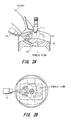
- FIG. 2 shows a fuel spray injected from a fuel injection valve and tumble flow which interferes with the fuel spray:
- FIG. 2A is a lateral view and
- FIG. 2B is an upper view.
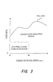
- FIG. 3 is a first map showing the operating range of a direct injection engine.
- FIG. 4 is a schematic diagram of a control system for a direct injection engine.
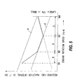
- FIG. 5 is a second map showing the relation between the engine rotation speed and the required fuel injection interval.
- FIG. 6 shows the influence of fuel pressure in during discrete double injection: FIG. 6A shows the behavior of two mixture clouds at high fuel pressure and FIG. 6B shows that at low fuel pressure.
- FIG. 7 is a third map showing the relation between the engine rotation speed and a target fuel pressure.
- FIG. 8 is a flowchart showing the routine for setting a target fuel pressure and fuel injection pulse widths.
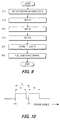
- FIG. 9 is a flowchart showing the routine for setting the fuel injection timing.
- FIG. 10 is a waveform diagram showing a fuel injection pulse signal.
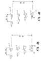
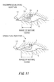
- FIG. 11 shows the behavior of mixture clouds produced by fuel spray into the combustion chamber.
- valve opening timing fuel injection timing
- valve opening period injection interval
- ignition timing are expressed in crank angle.
- a direct injection engine 1 comprises a cylinder head 2, a cylinder 4 formed in a cylinder block 3, and a piston 5 which slidably moves in the cylinder 4.
- the cylinder 4 and the piston 5 define a combustion chamber 6.
- An ignition plug 7 is positioned in the central section of the combustion chamber 6.
- the combustion chamber 6 is a pent roof type.
- a pair of intake ports 8a, 8b and a pair of exhaust ports 9a, 9b are disposed in mutually opposed positions sandwiching the spark plugs 7 on the ceiling of the combustion chamber 6.
- a pair of intake valves 10a, 10b open and close the opening of the intake ports 8a, 8b.
- a pair of exhaust valves 11a, 11b open and close the opening of the exhaust ports 9a, 9b.
- a fuel injection valve 12 is disposed on the ceiling of the combustion chamber 6, laterally facing the combustion chamber.
- the fuel injection valve 12 is positioned between each intake port 8a, 8b on a lateral side of each intake valve 10a, 10b in order to face the combustion chamber 6.
- the fuel injection valve 12 injects a fuel spray into the combustion chamber 6 with timing determined by a fuel injection pulse signal.
- the fuel spray mixes with air aspirated into the cylinder 4 from the intake ports 8a, 8b when each intake valve 10a, 10b is opened.
- the air-fuel mixture formed in the cylinder 4 is ignited by the spark plug 7 when compressed by the piston 5.
- the combustion gas depresses the piston 5 and provides a rotational force for the crankshaft. Thereafter when the exhaust valves 11a, 11b are opened during the exhaust stroke in which the piston 5 ascends, combustion gas is exhausted from each exhaust port 9a, 9b, and then the stroke cycle is continuously repeated.
- Each intake port 8a, 8b is provided with a tumble control valve 13 at a midway position.
- the tumble control valve 13 When the tumble control valve 13 is closed, intake air flows into the upper half of each intake port 8a, 8b as shown in FIG. 1A and the flow speed of the intake air is increased.
- tumble flow about an axis orthogonal to the center axis of the cylinder 4 is produced with a sufficient strength in the upper section of the head of the cylinder 5 as shown by an arrow in FIG. 2A.
- the tumble flow undergoes swirl in a longitudinal direction.
- FIG. 2B shows the tumble flow rising from the bottom of the cavity 5a.
- the tumble flow is represented with an incline in order to facilitate description.
- the direction of fuel injection of the fuel injection valve 12 is set to substantially the same direction as the direction of the tumble flow resulting from air intake.
- the fuel spray injected from the fuel injection valve 12 spreads out in the shape of an imaginary circular cone about the center of the fuel injection valve 12.
- the fuel spray is lead by the tumble flow towards the spark plug 7 and forms an ignitable mixture cloud at that point. Therefore stable stratified charge combustion operation is possible by igniting the mixture cloud reaching the proximity of the spark plugs 7.
- the stratified charge combustion region of the direct injection engine 1 is positioned towards low rotation speeds and low load.
- the load is expressed as a brake mean effective pressure.
- the stratified charge combustion region lies below the engine rotation speed of 3,600 rpm and below the brake mean effective pressure of 500-700 kPa.
- homogeneous combustion regions determined by the first map in FIG. 3 high rotation speed regions or high load regions
- a strong tumble flow is produced in the combustion chamber 6 even when the tumble control valve 13 is open.
- the direct injection engine 1 produces a homogeneous air-fuel mixture in the entire combustion chamber 6 by injecting fuel during the intake stroke with the tumble control valve 13 open in order to perform homogeneous combustion.
- the control system for the direct injection engine is provided with a spark plug 7, a fuel injection valve 12, a tumble control valve 13, a pressure regulator 14, a controller (ECM) 15, an accelerator pedal sensor 16, a crank angle sensor 17, an oxygen concentration sensor 18, and an airflow meter 19.
- the accelerator pedal sensor 16 detects the amount of accelerator pedal depression.
- the crank angle sensor 17 detects an engine rotation speed and a crank angle.
- the oxygen concentration sensor 18 and the airflow meter 19 are used for the air-fuel ratio control.
- the controller 15 is provided with a microprocessor having a central processing unit (CPU), a random access memory (RAM), a read only memory (ROM) and an input/output interface (I/O interface).
- CPU central processing unit
- RAM random access memory
- ROM read only memory
- I/O interface input/output interface
- a signal that is representative of the accelerator pedal depression amount from an accelerator pedal sensor 16, a signal showing a reference position and a position signal at 1 degree CA intervals from a crank angle sensor 17 are input to the controller 15.
- the amount of accelerator pedal depression corresponds to the engine load.
- the signal showing the reference position is a signal for controlling the ignition timing or the fuel injection period.
- the controller 15 controls the valve opening timing of the fuel injection valve 12, namely the fuel injection timing, and the valve opening period, namely the fuel injection amount.
- the controller 15 outputs a pulse signal corresponding to the calculated fuel injection amount to a drive circuit (not shown) of the fuel injection valve 12. Thereafter a drive current corresponding to the pulse signal is sent to the actuator of the fuel injection valve 12 from the drive circuit and the nozzle hole is opened by lifting a needle disposed in the fuel injection valve 12.
- the valve opening period of the fuel injection valve 12 lengthens and the fuel injection amount is increased.
- the ROM of the controller 15 stores a first map determining an operating range of the direct injection engine 1. When determining that the engine rotation speed and the engine load are in a homogeneous combustion region of the first map, the controller 15 sets the fuel injection timing to the intake stroke during which the piston is depressed. The controller 15 controls the air-fuel ratio in a narrow range about a stoichiometric air-fuel ratio in a homogeneous combustion region.
- the controller 15 sets the fuel injection timing to the latter half of the compression stroke during which the piston 5 ascends. In this case, the air-fuel ratio is controlled to a leaner value than the stoichiometric air-fuel ratio.
- the controller 15 controls the air-fuel ratio based on signals from the crank angle sensor 17, the oxygen concentration sensor 18, and an airflow meter 19.
- the controller 15 In the stratified charge combustion region, the controller 15 generates a fuel injection pulse signal comprising a first injection pulse and a second injection pulse having equal pulse widths. That is to say, fuel injection during the compression stroke in the stratified charge combustion region is performed equally on two occasions. Hereafter this type of fuel injection is termed discrete double injection.
- the fuel injection pulse signal is set so that a first mixture cloud formed from a fuel spray injected on the basis of a previous first fuel injection pulse reaches the proximity of the spark plugs at the ignition timing.
- the fuel injection pulse signal is further set so that a second mixture cloud formed from a fuel spray injected on the basis of a second fuel injection pulse successively follows the previously generated mixture cloud into proximity with the spark plug. This is enabled by adapting the engine fuel injection technique so that the principle of rapid-succession double fuel injection is applied to discrete double fuel injection in the compression stroke. In this manner, two mixture clouds become superimposed in proximity to the spark plugs at the ignition timing.
- Air flow generated by the fuel injected during the first injection reduces the pressure near the fuel injection valve.
- fuel injected during the second injection is sucked into proximity with the fuel injection valve. This phenomenon makes the travel speed of the mixture cloud produced by the fuel spray during the second fuel injection greater than the travel speed of the mixture cloud produced by the fuel spray during the first fuel injection.
- the pulse signal output during the compression stroke is divided into two signals of substantially equal pulse width in order to apply the principle to rapid-succession double injection.
- the two mixture clouds produced from respective fuel sprays separately progress towards the spark plugs.
- the latter (hereinafter second) mixture cloud follows the previously generated (hereinafter first) mixture cloud.
- the latter mixture cloud catches up with the first mixture cloud and the two clouds become superimposed.
- the second mixture cloud overtakes the first mixture cloud and elongates the superimposed mixture cloud.
- the degree of charge stratification can be increased to a degree higher than that obtained by a single fuel injection which does not perform discrete fuel injection when the two mixture clouds are superimposed in proximity to the spark plugs at the ignition timing.
- the direct injection engine can perform stratified charge combustion with stability.
- the fuel injection interval Di required to superimpose the two mixture clouds in proximity to the spark plugs 7 at the ignition timing is varied in response to the engine rotation speed.
- the controller 15 computes a required fuel injection interval Di in response to the engine rotation speed by looking up a second map as shown in FIG. 5 in order to superimpose the two mixture clouds in proximity to the spark plugs 7 at the ignition timing in all stratified charge combustion regions.
- the second map is stored in the ROM of the controller 15 and specifying the relation of the engine rotation speed and the required fuel injection interval Di.
- the required fuel injection interval Di corresponds to the onset interval of the two injection pulse and is expressed as a crank angle (degree CA).
- a different relation between the engine rotation speed and the required injection interval Di shown by the thick solid line is set in region A from the first engine rotation speed N1 to the second engine rotation speed N2, in region B from the second engine rotation speed N2 to the third engine rotation speed N3, and in region C from the third engine rotation speed N3 to the fourth engine rotation speed N4.
- the first, second, third, and fourth speed (N1, N2, N3, and N4) are preset to be 600, 1,200, 2,000, 3,600 rpm.
- the required fuel injection interval Di is set to increase with decrease in engine rotation speed.
- the controller 15 sets a target fuel pressure tFp for injected fuel in response to the engine rotation speed based on a third map as shown in FIG. 7.
- the third map is stored in the ROM of the controller 15 and specifies the relation of the engine rotation speed and the target fuel pressure tFp.
- a target fuel pressure tFp is set so that stratified charge combustion is suitably produced when the fuel injection interval corresponds to the required fuel injection interval Di.
- the fuel pressure supplied to the fuel injection valve is set according to the required fuel injection interval Di in order to enable a required fuel injection interval Di which varies in response to the engine rotation speed. The reason for this will be described hereafter.
- FIG. 6 shows a model comparison of the movement of two mixture clouds corresponding to a first and second fuel injection.
- the mixture clouds are identical with respect to the fuel injection amount, fuel injection timing and ignition timing and only differ with respect to fuel pressure.
- the interval between the first and second fuel injection is 20 degrees CA and the crank angle from completion of discrete fuel injection to the ignition timing is approximately 20 degrees CA.
- the difference of fuel pressure results in a difference in the manner in which the two mixture clouds reach the proximity of the spark plugs 7.
- FIG. 6 shows two mixture clouds immediately after completion of discrete fuel injection at the uppermost stage as shown in the figure.
- the lowest stage in the figure shows the two mixture clouds at the ignition timing with the downward passage of the two mixture clouds shown therebetween.
- the travel speed of the first mixture cloud 21 (the mixture cloud resulting from a fuel spray injection by the first pulse) is more rapid than during low fuel pressure conditions.
- the first mixture cloud 21 has slightly passed through the spark plug 7 before the second mixture cloud 22 (the mixture clouds resulting from a fuel spray injection by the second pulse signal) catches up (refer to the lowest stage in FIG. 6A).
- the second mixture cloud 22 catches up to the first mixture cloud 21 and both mixtures become superimposed.
- the fuel pressure becomes excessively high in this case.
- the travel speed of the first mixture cloud 21 is delayed when the fuel pressure is reduced.
- the first mixture cloud 21 reaches the proximity of the spark plug at the ignition timing.
- the second mixture cloud 22 reaches the proximity of the spark plug in the same manner and both mixture clouds become superimposed (refer to the lowermost stage in FIG. 6B).
- the two mixture clouds become superimposed at the position closer to the fuel injection valve as the fuel pressure is reduced.
- the target fuel pressure tFp is reduced with decrease in engine rotation speed in the region A.
- the target fuel pressure Fp1 at a minimum rotation speed N1 (for example 600 rpm) of the engine becomes the lowest value in the region A.
- the target fuel pressure tFp has a tendency of decreasing with increase in the required fuel injection interval Di.
- the target fuel pressure tFp increases as the engine rotation speed increases from the minimum rotation speed N1.
- an upper limit Fpmax on the fuel pressure exists due to the operational capacity of the fuel supply device.
- the fuel supply device is provided with a fuel pump (not shown) for pumping fuel under pressure and a pressure regulator 14 which is provided downstream of the fuel pump and which maintains the fuel pressure to a regulated value.
- a fuel pump not shown
- a pressure regulator 14 which is provided downstream of the fuel pump and which maintains the fuel pressure to a regulated value.
- the required fuel injection interval Di must be larger than or equal to this lower limit.
- the lower limit of the required fuel injection interval Di is shown by the thin solid line ⁇ in FIG. 5. The lower limit on the required fuel injection interval Di decreases with increase in engine rotation speed.
- the required fuel injection interval Di When the engine rotation speed rises to the second speed N2, the required fuel injection interval Di reaches the thin solid line ⁇ and the fuel pressure does not undergo further increase.
- the required fuel injection interval Di when the engine rotation speed reaches values greater than or equal to the second speed N2 (for example 1,200 rpm), the required fuel injection interval Di is set to a lower limit corresponding to the fuel pressure upper limit Fpmax.
- an upper limit on the required fuel injection interval Di exists resulting from the existence of the fuel pressure lower limit Fpmin.
- the thin solid line ⁇ in FIG. 5 expresses the upper limit of the required fuel injection interval Di corresponding to the fuel pressure lower limit Fpmin.
- the broken line in the lower section of FIG. 5 represents the minimum value required for driving the fuel injection valve 12, that is to say, the minimum value resulting from the response delay in driving the fuel injection valve. The reason for the existence of the minimum value will be described in detail below.
- the broken line and the thin solid line ⁇ corresponding to the upper limiting value on the fuel pressure intersect at the third speed N3 (for example 2,000 rpm).
- the required fuel injection interval Di when in a rotation speed region where the engine rotation speed is greater than the third speed N3 (region C), the required fuel injection interval Di is set to a lower limit resulting from the response delay in driving the fuel injection valve.
- the required fuel injection interval Di is increased with increasing engine rotation speed as shown by the broken line.
- the target fuel pressure tFp is varied in order to enable a required fuel injection interval Di.
- the target fuel pressure tFp is decreased with increasing engine rotation speed in region C.
- the fourth speed N4 (for example 3,600 rpm) is an engine rotation speed which determines the boundary for the stratified charge combustion region and the homogeneous combustion region.
- the required fuel injection interval Di is set when the engine rotation speed is less than the fourth speed N4 in the second map in FIG. 5.
- the target fuel pressure tFp in response to the engine rotation speed will be described below.
- the target fuel pressure increases with increasing engine rotation speed from an engine rotation speed N1 to N2.
- the target fuel pressure tFp is fixed to the upper limiting value between an engine rotation speed N2 to N3.
- the target fuel pressure tFp decreases with increasing engine rotation speed from an engine rotation speeds N3 to N4.
- the characteristics of the required fuel injection interval Di in region A are shown as linear in FIG. 5 and FIG. 7. However those characteristics are not limited in this regard and may be curved.
- the controller 15 controls the ignition timing of the spark plug 7 in response to operating conditions. In the stratified charge combustion region, since the optimal ignition timing varies in response to the engine rotation speed or the load, the controller 15 calculates an optimal ignition timing in response to engine rotation speed and load. An ignition signal for realizing the calculated ignition timing is output to the drive circuit of the ignition coils 13a, 13b shown in FIG. 4. Sparking occurs between the electrodes of the spark plug 7 based on the ignition signal.
- the required fuel injection interval Di is affected. Therefore the actual value of the required fuel injection interval Di shown in FIG. 5 is determined by experiments taking the ignition timing into account.
- This routine is executed by the controller 15 at predetermined intervals, for example at intervals of 10 milliseconds.
- step S1 operating conditions such as the engine rotation speed Ne and the engine load are detected. Then in a step S2, the required fuel amount per cylinder is computed on the basis of the operating conditions.
- the target fuel pressure tFp during discrete fuel injection is set on the basis of the engine rotation speed Ne by looking up a third map as shown in FIG. 7.
- a total fuel injection pulse width T is set in order to supply a required fuel amount with the target fuel pressure tFp.
- a step S5 1/2 of T is set as a fuel injection pulse width T1 for the first fuel injection and 1/2 of T is set as a fuel injection pulse width T2 for the second fuel injection. That is to say, the division ratio of the first fuel injection and the second fuel injection is 1:1.
- T1 + T2 T.
- T1 and T2 are stored in the register of the CPU.
- a target fuel pressure tFp is output to the drive circuit of the pressure regulator 14.
- the fuel pressure is regulated by the duty-controlled pressure regulator 14.
- the drive circuit of the pressure regulator 14 performs duty control in order to obtain a target fuel pressure tFp.
- a routine will be described below for setting the onset timing IT1, IT2 of the fuel injection pulse signal which is divided into two in the stratified charge combustion region. That is to say, the fuel injection start timings for the first and second injection are set.
- the routine is executed by the controller 15 at a predetermined interval, for example 10 milliseconds.
- a step S11 operating conditions such as the engine rotation speed Ne and engine load are detected.
- a step S12 a first fuel injection start timing IT1 [degree CA BTDC] is set on the basis of operating conditions.
- a required fuel injection interval Di [degree CA] is set by looking up a second map shown in FIG. 5 based on the engine rotation speed Ne.
- a value delayed from the first fuel injection start timing IT1 by the required fuel injection interval Di is set as a second fuel injection start timing IT2 [degree CA BTDC].
- the two fuel injection start timings IT1, IT2 are stored in the register of the CPU. The two fuel injection start timings IT1, IT2 are naturally set in the compression stroke.
- a step S16 the controller 15 executes a fuel injection control.
- a fuel injection pulse signal consisting of the two fuel injection pulse is produced as shown in FIG. 10 based on the fuel injection start timing IT1, IT2 and fuel injection pulse widths T1, T2 stored in the register of the CPU.
- the controller 15 outputs this fuel injection pulse signal to the drive circuit of the fuel injection valve 12.
- a required fuel injection interval Di is determined for the two fuel injection so that the two mixture clouds are superimposed in proximity to the spark plug 7 at the ignition timing, by applying the principle of rapid-succession double fuel injection.
- the first and second fuel injection pulse widths T1, T2 correspond to half the pulse width T of a single injection, the dimensions of the mixture clouds when superimposed are approximately half those resulting from a single (non-divided) injection pulse single.
- Reference numeral 31 shown in the upper panel denotes the first mixture cloud and that designated by the reference numeral 32 is the second mixture cloud.
- the overall range in the dimensions of the mixture cloud is more narrow when two mixture clouds 31, 32 are produced by discrete double fuel injection as shown in the upper panel than a mixture cloud 33 produced by a single fuel injection as shown in the lower panel.
- the two mixture clouds produced by a fuel spray injection due to a first and a second fuel injection pulse are superimposed in proximity to the spark plug at the ignition timing.
- region A near the lowest rotation speed shown in FIG. 5, low engine rotation speeds tend to lengthen the time from completion of the fuel injection to the ignition timing. As a result, in region A, the required fuel injection interval increases with decreasing engine rotation speed. Since the routine is adapted to delay superimposition of the two mixture clouds, in region A, it is possible superimpose the two mixture clouds in proximity to the spark plug at the ignition timing.
- a rotation speed region (region C in FIG. 5) where a limiting value resulting from the required time for driving the fuel injection valve is set as a required fuel injection interval Di, it is possible to ensure a minimum fuel injection interval and perform discrete double fuel injection applying the principle of rapid-succession double injection.
- an air guide is employed as a method of introducing an air-fuel mixture from a fuel injection valve 12 to the spark plug 7.
- this invention is not limited in this respect and it is possible to apply the invention to a direct injection engine with a wall guide.
- An air guide is a system of generating a tumble flow (swirl in a longitudinal direction) in air flowing into the combustion chamber 6 from the intake ports 8a, 8b by closing the tumble control valve 25 (gas flow generating means).
- the shape of a cavity provided on the piston head and the angle of incidence of intake air flowing into the combustion chamber 6 from the intake ports 8a, 8b is determined so that fuel injected from the fuel injection valve 12 enters the tumble flow and is transported to the spark plug 7.
- a wall guide is a different method of transporting an air-fuel mixture into proximity to the spark plug and comprises a system of using a swirl flow (swirl in a lateral direction) generated by the gas flow generating means.
- the swirl flow leads an air-fuel mixture resulting from the fuel spray along the wall of the cavity provided as an indentation on the piston head to the proximity of the spark plugs.
- the wall guide system is disclosed in Tokkai Hei 10-339138 published by the Japanese Patent Office.
- a fuel injection pulse signal generated during the compression stroke in the stratified charge combustion region consists of two pulses having exactly the same fuel injection pulse width.
- the fuel injection pulse widths of the first and second pulses may be different to a certain degree.
- the onset interval of the two fuel injection pulses as shown in FIG. 10 has been expressed as a fuel injection interval.
- the interval from the onset of the first fuel injection pulse to the onset of the second fuel injection pulse (that is to say, the interval from the right end of T1 to IT2) may be expressed as the fuel injection interval.
Landscapes
- Engineering & Computer Science (AREA)
- Chemical & Material Sciences (AREA)
- Combustion & Propulsion (AREA)
- Mechanical Engineering (AREA)
- General Engineering & Computer Science (AREA)
- Electrical Control Of Air Or Fuel Supplied To Internal-Combustion Engine (AREA)
- Combustion Methods Of Internal-Combustion Engines (AREA)
- Fuel-Injection Apparatus (AREA)
- Combined Controls Of Internal Combustion Engines (AREA)
Applications Claiming Priority (2)
| Application Number | Priority Date | Filing Date | Title |
|---|---|---|---|
| JP2001001528 | 2001-01-09 | ||
| JP2001001528A JP3952693B2 (ja) | 2001-01-09 | 2001-01-09 | 筒内直接燃料噴射式火花点火エンジンの燃料噴射制御装置 |
Publications (3)
| Publication Number | Publication Date |
|---|---|
| EP1223329A2 true EP1223329A2 (fr) | 2002-07-17 |
| EP1223329A3 EP1223329A3 (fr) | 2004-01-28 |
| EP1223329B1 EP1223329B1 (fr) | 2005-07-20 |
Family
ID=18870160
Family Applications (1)
| Application Number | Title | Priority Date | Filing Date |
|---|---|---|---|
| EP01130446A Expired - Lifetime EP1223329B1 (fr) | 2001-01-09 | 2001-12-20 | Appareil et procédé de commande de l'injection de carburant pour un moteur à allumage commandé avec injection directe |
Country Status (3)
| Country | Link |
|---|---|
| EP (1) | EP1223329B1 (fr) |
| JP (1) | JP3952693B2 (fr) |
| DE (1) | DE60112031T2 (fr) |
Cited By (9)
| Publication number | Priority date | Publication date | Assignee | Title |
|---|---|---|---|---|
| FR2849898A1 (fr) * | 2003-01-13 | 2004-07-16 | Renault Sa | Procede de commande de moteur a combustion interne et moteur a combustion interne |
| EP1467075A1 (fr) * | 2003-04-03 | 2004-10-13 | Nissan Motor Co., Ltd. | Système d'admission d'un moteur à combustion interne |
| US6851408B2 (en) * | 2002-12-25 | 2005-02-08 | Nissan Motor Co., Ltd. | Direct fuel injection engine |
| WO2005103468A1 (fr) * | 2004-04-14 | 2005-11-03 | Daimlerchrysler Ag | Procede permettant de faire fonctionner un moteur a combustion interne dans la phase de post-demarrage a de faibles temperatures |
| CN1316147C (zh) * | 2003-04-03 | 2007-05-16 | 日产自动车株式会社 | 用于内燃机的吸气设备 |
| FR2900685A1 (fr) * | 2006-05-05 | 2007-11-09 | Peugeot Citroen Automobiles Sa | Systeme d'alimentation en carburant d'un moteur a combustion stratifiee de vehicule automobile. |
| US7360522B2 (en) * | 2006-07-25 | 2008-04-22 | General Electric Company | System and method for operating a turbo-charged engine |
| US7487756B2 (en) | 2005-11-30 | 2009-02-10 | Toyota Jidosha Kabushiki Kaisha | Direct fuel injection-type spark ignition internal combustion engine |
| WO2016035276A1 (fr) * | 2014-09-04 | 2016-03-10 | Toyota Jidosha Kabushiki Kaisha | Moteur à combustion interne |
Families Citing this family (5)
| Publication number | Priority date | Publication date | Assignee | Title |
|---|---|---|---|---|
| US7369934B2 (en) * | 2004-08-27 | 2008-05-06 | Optimum Power Technology, L.P. | Predictive engine combustion management |
| JP4594260B2 (ja) * | 2006-03-15 | 2010-12-08 | 株式会社豊田中央研究所 | 内燃機関の混合気の不均一度取得装置、及び混合気状態取得装置 |
| DE102008038823B4 (de) * | 2008-01-23 | 2017-12-14 | GM Global Technology Operations LLC (n. d. Ges. d. Staates Delaware) | Kraftstoffeinspritzsystem, Motorsystem und Verfahren zum Betreiben eines Motors |
| JP6098489B2 (ja) * | 2013-11-25 | 2017-03-22 | マツダ株式会社 | 直噴ガソリンエンジンの制御装置 |
| JP6453439B2 (ja) * | 2015-03-05 | 2019-01-16 | 日立オートモティブシステムズ株式会社 | 燃料噴射弁、燃料噴射弁の制御装置、及び制御方法 |
Citations (4)
| Publication number | Priority date | Publication date | Assignee | Title |
|---|---|---|---|---|
| JPH10339138A (ja) | 1997-06-04 | 1998-12-22 | Nissan Motor Co Ltd | 筒内直接噴射式内燃機関 |
| JPH1182030A (ja) | 1997-09-05 | 1999-03-26 | Nissan Motor Co Ltd | 筒内直噴式火花点火エンジンの燃料噴射制御装置 |
| JP2000087750A (ja) | 1998-09-09 | 2000-03-28 | Nissan Motor Co Ltd | 筒内直接噴射式内燃機関 |
| JP2001001528A (ja) | 1999-06-04 | 2001-01-09 | Eastman Kodak Co | インクジェットプリントヘッド |
Family Cites Families (5)
| Publication number | Priority date | Publication date | Assignee | Title |
|---|---|---|---|---|
| DE19602065C2 (de) * | 1996-01-20 | 2001-08-09 | Daimler Chrysler Ag | Verfahren zum Betrieb eines Verbrennungsmotors |
| DE19815266B4 (de) * | 1997-04-16 | 2008-09-18 | Volkswagen Ag | Verfahren zur Einspritzung von Kraftstoff in eine Brennkraftmaschine |
| JP3325232B2 (ja) * | 1997-09-29 | 2002-09-17 | マツダ株式会社 | 筒内噴射式エンジン |
| JP2000054881A (ja) * | 1998-08-06 | 2000-02-22 | Mazda Motor Corp | 筒内噴射式エンジンの制御装置 |
| JP3671785B2 (ja) * | 1999-12-15 | 2005-07-13 | 株式会社日立製作所 | 筒内噴射型内燃機関の燃料噴射装置 |
-
2001
- 2001-01-09 JP JP2001001528A patent/JP3952693B2/ja not_active Expired - Fee Related
- 2001-12-20 DE DE60112031T patent/DE60112031T2/de not_active Expired - Lifetime
- 2001-12-20 EP EP01130446A patent/EP1223329B1/fr not_active Expired - Lifetime
Patent Citations (4)
| Publication number | Priority date | Publication date | Assignee | Title |
|---|---|---|---|---|
| JPH10339138A (ja) | 1997-06-04 | 1998-12-22 | Nissan Motor Co Ltd | 筒内直接噴射式内燃機関 |
| JPH1182030A (ja) | 1997-09-05 | 1999-03-26 | Nissan Motor Co Ltd | 筒内直噴式火花点火エンジンの燃料噴射制御装置 |
| JP2000087750A (ja) | 1998-09-09 | 2000-03-28 | Nissan Motor Co Ltd | 筒内直接噴射式内燃機関 |
| JP2001001528A (ja) | 1999-06-04 | 2001-01-09 | Eastman Kodak Co | インクジェットプリントヘッド |
Cited By (12)
| Publication number | Priority date | Publication date | Assignee | Title |
|---|---|---|---|---|
| US6851408B2 (en) * | 2002-12-25 | 2005-02-08 | Nissan Motor Co., Ltd. | Direct fuel injection engine |
| EP1433935A3 (fr) * | 2002-12-25 | 2006-06-28 | Nissan Motor Co., Ltd. | Moteur à injection directe de carburant |
| FR2849898A1 (fr) * | 2003-01-13 | 2004-07-16 | Renault Sa | Procede de commande de moteur a combustion interne et moteur a combustion interne |
| EP1467075A1 (fr) * | 2003-04-03 | 2004-10-13 | Nissan Motor Co., Ltd. | Système d'admission d'un moteur à combustion interne |
| US6918372B2 (en) | 2003-04-03 | 2005-07-19 | Nissan Motor Co., Ltd. | Intake system of internal combustion engine |
| CN1316147C (zh) * | 2003-04-03 | 2007-05-16 | 日产自动车株式会社 | 用于内燃机的吸气设备 |
| WO2005103468A1 (fr) * | 2004-04-14 | 2005-11-03 | Daimlerchrysler Ag | Procede permettant de faire fonctionner un moteur a combustion interne dans la phase de post-demarrage a de faibles temperatures |
| US7370629B2 (en) | 2004-04-14 | 2008-05-13 | Daimler Ag | Method for operating an internal combustion engine with direct fuel injection during a post-start phase |
| US7487756B2 (en) | 2005-11-30 | 2009-02-10 | Toyota Jidosha Kabushiki Kaisha | Direct fuel injection-type spark ignition internal combustion engine |
| FR2900685A1 (fr) * | 2006-05-05 | 2007-11-09 | Peugeot Citroen Automobiles Sa | Systeme d'alimentation en carburant d'un moteur a combustion stratifiee de vehicule automobile. |
| US7360522B2 (en) * | 2006-07-25 | 2008-04-22 | General Electric Company | System and method for operating a turbo-charged engine |
| WO2016035276A1 (fr) * | 2014-09-04 | 2016-03-10 | Toyota Jidosha Kabushiki Kaisha | Moteur à combustion interne |
Also Published As
| Publication number | Publication date |
|---|---|
| JP3952693B2 (ja) | 2007-08-01 |
| DE60112031T2 (de) | 2006-04-13 |
| EP1223329A3 (fr) | 2004-01-28 |
| EP1223329B1 (fr) | 2005-07-20 |
| DE60112031D1 (de) | 2005-08-25 |
| JP2002201990A (ja) | 2002-07-19 |
Similar Documents
| Publication | Publication Date | Title |
|---|---|---|
| EP0661432B1 (fr) | Dispositif et méthode de commande de moteur à combustion interne | |
| EP1223329B1 (fr) | Appareil et procédé de commande de l'injection de carburant pour un moteur à allumage commandé avec injection directe | |
| US20050166891A1 (en) | Controller for direct injection internal combustion engine | |
| KR101824857B1 (ko) | 내연 기관 제어 장치 및 내연 기관 제어 방법 | |
| US8718903B2 (en) | Direct injection spark ignition internal combustion engine, and fuel injection control method therefor | |
| US5975045A (en) | Apparatus and method for controlling direct injection engines | |
| JPH1182030A (ja) | 筒内直噴式火花点火エンジンの燃料噴射制御装置 | |
| EP1342914B1 (fr) | Moteur à combustion interne à injection directe | |
| US7134421B2 (en) | Direct fuel injection spark ignition internal combustion engine | |
| CN111971466B (zh) | 内燃机的控制方法及内燃机 | |
| JP2004353485A (ja) | 予混合圧縮着火燃焼内燃機関の吸気制御方法 | |
| EP1688616B1 (fr) | Moteur à allumage commandé à injection directe | |
| US20230287845A1 (en) | Internal combustion engine | |
| JP2002339782A (ja) | 火花点火式直噴エンジンの制御装置 | |
| JP4360323B2 (ja) | 筒内直接噴射式火花点火内燃機関の制御装置 | |
| JPH10176628A (ja) | 筒内噴射式火花点火機関 | |
| JP2022150466A (ja) | エンジンシステム | |
| JP2004137989A (ja) | 内燃機関の燃焼制御装置 | |
| JP2004340031A (ja) | 内燃機関の混合気噴射装置 | |
| JPH1077875A (ja) | 筒内噴射式エンジン | |
| JP2007198324A (ja) | 筒内直接噴射式火花点火内燃機関 | |
| JP2005194883A (ja) | 筒内噴射式内燃機関 |
Legal Events
| Date | Code | Title | Description |
|---|---|---|---|
| PUAI | Public reference made under article 153(3) epc to a published international application that has entered the european phase |
Free format text: ORIGINAL CODE: 0009012 |
|
| 17P | Request for examination filed |
Effective date: 20011220 |
|
| AK | Designated contracting states |
Kind code of ref document: A2 Designated state(s): AT BE CH CY DE DK ES FI FR GB GR IE IT LI LU MC NL PT SE TR |
|
| AX | Request for extension of the european patent |
Free format text: AL;LT;LV;MK;RO;SI |
|
| PUAL | Search report despatched |
Free format text: ORIGINAL CODE: 0009013 |
|
| AK | Designated contracting states |
Kind code of ref document: A3 Designated state(s): AT BE CH CY DE DK ES FI FR GB GR IE IT LI LU MC NL PT SE TR |
|
| AX | Request for extension of the european patent |
Extension state: AL LT LV MK RO SI |
|
| RIC1 | Information provided on ipc code assigned before grant |
Ipc: 7F 02D 41/30 A Ipc: 7F 02D 41/40 B |
|
| 17Q | First examination report despatched |
Effective date: 20040629 |
|
| AKX | Designation fees paid |
Designated state(s): DE FR GB |
|
| GRAP | Despatch of communication of intention to grant a patent |
Free format text: ORIGINAL CODE: EPIDOSNIGR1 |
|
| RTI1 | Title (correction) |
Free format text: FUEL INJECTION CONTROL DEVICE AND METHOD FOR DIRECT INJECTION SPARK-IGNITION ENGINE |
|
| GRAS | Grant fee paid |
Free format text: ORIGINAL CODE: EPIDOSNIGR3 |
|
| GRAA | (expected) grant |
Free format text: ORIGINAL CODE: 0009210 |
|
| AK | Designated contracting states |
Kind code of ref document: B1 Designated state(s): DE FR GB |
|
| REG | Reference to a national code |
Ref country code: GB Ref legal event code: FG4D |
|
| REF | Corresponds to: |
Ref document number: 60112031 Country of ref document: DE Date of ref document: 20050825 Kind code of ref document: P |
|
| ET | Fr: translation filed | ||
| PLBE | No opposition filed within time limit |
Free format text: ORIGINAL CODE: 0009261 |
|
| STAA | Information on the status of an ep patent application or granted ep patent |
Free format text: STATUS: NO OPPOSITION FILED WITHIN TIME LIMIT |
|
| 26N | No opposition filed |
Effective date: 20060421 |
|
| PGFP | Annual fee paid to national office [announced via postgrant information from national office to epo] |
Ref country code: DE Payment date: 20121213 Year of fee payment: 12 |
|
| PGFP | Annual fee paid to national office [announced via postgrant information from national office to epo] |
Ref country code: GB Payment date: 20121219 Year of fee payment: 12 |
|
| PGFP | Annual fee paid to national office [announced via postgrant information from national office to epo] |
Ref country code: FR Payment date: 20130107 Year of fee payment: 12 |
|
| REG | Reference to a national code |
Ref country code: DE Ref legal event code: R119 Ref document number: 60112031 Country of ref document: DE |
|
| GBPC | Gb: european patent ceased through non-payment of renewal fee |
Effective date: 20131220 |
|
| REG | Reference to a national code |
Ref country code: FR Ref legal event code: ST Effective date: 20140829 |
|
| REG | Reference to a national code |
Ref country code: DE Ref legal event code: R119 Ref document number: 60112031 Country of ref document: DE Effective date: 20140701 |
|
| PG25 | Lapsed in a contracting state [announced via postgrant information from national office to epo] |
Ref country code: DE Free format text: LAPSE BECAUSE OF NON-PAYMENT OF DUE FEES Effective date: 20140701 |
|
| PG25 | Lapsed in a contracting state [announced via postgrant information from national office to epo] |
Ref country code: GB Free format text: LAPSE BECAUSE OF NON-PAYMENT OF DUE FEES Effective date: 20131220 Ref country code: FR Free format text: LAPSE BECAUSE OF NON-PAYMENT OF DUE FEES Effective date: 20131231 |