EP1222959A2 - Verfahren und Vorrichtung zum Regenerieren eines Adsorbers - Google Patents
Verfahren und Vorrichtung zum Regenerieren eines Adsorbers Download PDFInfo
- Publication number
- EP1222959A2 EP1222959A2 EP01130647A EP01130647A EP1222959A2 EP 1222959 A2 EP1222959 A2 EP 1222959A2 EP 01130647 A EP01130647 A EP 01130647A EP 01130647 A EP01130647 A EP 01130647A EP 1222959 A2 EP1222959 A2 EP 1222959A2
- Authority
- EP
- European Patent Office
- Prior art keywords
- heated
- regeneration gas
- thermal oil
- stream
- gas stream
- Prior art date
- Legal status (The legal status is an assumption and is not a legal conclusion. Google has not performed a legal analysis and makes no representation as to the accuracy of the status listed.)
- Withdrawn
Links
Images


Classifications
-
- B—PERFORMING OPERATIONS; TRANSPORTING
- B01—PHYSICAL OR CHEMICAL PROCESSES OR APPARATUS IN GENERAL
- B01J—CHEMICAL OR PHYSICAL PROCESSES, e.g. CATALYSIS OR COLLOID CHEMISTRY; THEIR RELEVANT APPARATUS
- B01J20/00—Solid sorbent compositions or filter aid compositions; Sorbents for chromatography; Processes for preparing, regenerating or reactivating thereof
- B01J20/30—Processes for preparing, regenerating, or reactivating
- B01J20/34—Regenerating or reactivating
- B01J20/3483—Regenerating or reactivating by thermal treatment not covered by groups B01J20/3441 - B01J20/3475, e.g. by heating or cooling
-
- B—PERFORMING OPERATIONS; TRANSPORTING
- B01—PHYSICAL OR CHEMICAL PROCESSES OR APPARATUS IN GENERAL
- B01J—CHEMICAL OR PHYSICAL PROCESSES, e.g. CATALYSIS OR COLLOID CHEMISTRY; THEIR RELEVANT APPARATUS
- B01J20/00—Solid sorbent compositions or filter aid compositions; Sorbents for chromatography; Processes for preparing, regenerating or reactivating thereof
- B01J20/30—Processes for preparing, regenerating, or reactivating
- B01J20/34—Regenerating or reactivating
- B01J20/345—Regenerating or reactivating using a particular desorbing compound or mixture
- B01J20/3458—Regenerating or reactivating using a particular desorbing compound or mixture in the gas phase
-
- B—PERFORMING OPERATIONS; TRANSPORTING
- B01—PHYSICAL OR CHEMICAL PROCESSES OR APPARATUS IN GENERAL
- B01J—CHEMICAL OR PHYSICAL PROCESSES, e.g. CATALYSIS OR COLLOID CHEMISTRY; THEIR RELEVANT APPARATUS
- B01J2220/00—Aspects relating to sorbent materials
- B01J2220/50—Aspects relating to the use of sorbent or filter aid materials
- B01J2220/60—Use in several different columns
- B01J2220/603—Use in several different columns serially disposed columns
-
- B—PERFORMING OPERATIONS; TRANSPORTING
- B01—PHYSICAL OR CHEMICAL PROCESSES OR APPARATUS IN GENERAL
- B01J—CHEMICAL OR PHYSICAL PROCESSES, e.g. CATALYSIS OR COLLOID CHEMISTRY; THEIR RELEVANT APPARATUS
- B01J2220/00—Aspects relating to sorbent materials
- B01J2220/50—Aspects relating to the use of sorbent or filter aid materials
- B01J2220/60—Use in several different columns
- B01J2220/606—Use in several different columns parallel disposed columns
Definitions
- the invention relates to a method and a device for regenerating a loaded adsorber by means of a heated regeneration gas stream.
- the adsorption takes place at a temperature T, while the regeneration of a loaded adsorber is carried out at a temperature> T.
- the impurities retained in the adsorption cycle by the adsorbent or adsorbent are desorbed again by passing a regeneration gas over the adsorbent at a temperature T 2 which, as already mentioned, is higher than the temperature T 1 in the adsorption cycle.
- the temperature difference T 2 -T 1 is at least 30 K and is, for example, in the range from 30 to 250 K, preferably 80 and 180 K.
- Usual adsorption temperatures are 5 to 35 ° C., preferably 7 to 20 ° C.
- Such methods are also used, for example, to purify feed air for a Cryogenic air separation is applied, whereby atmospheric air compresses and is supplied for cleaning. The cleaned air is then cooled and at least partially fed to a rectification column.
- at least one Pair of switchable adsorbers that load alternately (adsorption cycle) and desorbed (regeneration cycle) are provided; such as from the DE-A 20 64 137 known.
- the pair of adsorbers which are alternately thermally regenerated at 80 to 250 ° C, for pre-cleaning the air before the cold part of a rectifying air separation is a well-known and used technology.
- C 2 H 2 which represents a high hazard potential in liquid oxygen (LOX).
- the adsorbers used for the pre-cleaning are, as soon as they are loaded, by means of a residual gas stream withdrawn from the air separation plant regenerated.
- This residual gas flow is at the outlet of the main heat exchanger with approx. 20 ° C before. It is therefore initially on a during the regeneration cycle Temperature between 180 and 220 ° C heated and over the loaded adsorber directed.
- the heating of the aforementioned regeneration gas stream has so far been carried out in Usually by means of an electric heater. This procedure is based on the illustrated in Figure 1 embodiment.
- FIG. 1 shows a pair of adsorbers A and A ', which is compressed via line 1 and Feed air flow to be cleaned is supplied. While one of the adsorbers in the Adsorption clock is located, the other adsorber or the one arranged therein Adsorbent desorbed or regenerated. The disruptive of the aforementioned Component-free feed air is removed via line 2 from adsorbers A and A ' deducted and one not shown in Figure 1 and in Figures 2 to 5 fed cryogenic air separation plant.
- the heating of the loaded adsorbent by means of the hot regeneration gas stream to a cooling step is separated from the residual gas stream with a Temperature of approx. 20 ° C. As a result, this is in the Adsorbent bulk temperature profile built up by the Adsorbent bed pushed.
- the cooling step is finished when in the entire adsorbent bed there is a temperature close to the Temperature of the residual gas stream is.
- Such a cooling step prevents the adsorbers from being hot after the switchover Feed air is fed via line 2 to the cryogenic air separation plant, which would bring significant disadvantages.
- the Residual gas flow is not required.
- a heat accumulator B can be charged during this time become.
- residual gas is additionally heated and passed through the heat store B. and deducted via line 7 '. As soon as reheated residual gas is required, becomes a partial flow of the residual gas flow through the electric heater E and Partial flow through the heat accumulator B.
- the Adsorber As soon as the regeneration of a loaded adsorber has ended, the Adsorber "switched". This means that now the adsorber that is was previously in the adsorption cycle, is regenerated, while the previously regenerated Adsorber is switched into the adsorption cycle.
- the object of the present invention is to provide a method and an apparatus for Regeneration of a loaded adsorber by means of a heated one Specify regeneration gas flow, the or the described State of the art is more economical or can be operated more easily.
- thermal oil system in which the Combustion of fossil fuels and / or suitable residues and / or through the Using suitable waste heat, a hot thermal oil flow is generated which - as Acting heat transfer medium - heats the regeneration gas flow.
- the invention makes it possible to heat the regeneration gas stream considerably cheaper than this is possible when using an electric heater.
- Another advantage of the invention is that the one used Regeneration gas flow / thermal oil heat exchanger only a pressure loss of approx.2.5 has mbar.
- a heat accumulator generates a pressure loss of approx. 50 mbar - including the pressure losses caused by flaps, pipes, etc.
- a heat exchanger W is arranged in line 4, in which at least a partial stream of the residual gas is drawn off and fed to the adsorbers for the purpose of regeneration.
- a heated thermal oil flow which is generated in a thermal oil system not shown in FIGS. 2 to 5, is passed through the heat exchanger W via the line 10 shown in broken lines and thus heats the regeneration gas flow carried in the line 4.
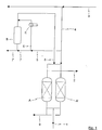
- FIG. 3 shows an exemplary embodiment which differs from the exemplary embodiment illustrated in FIG. 1 only in that the heat exchanger W is connected upstream of the electrical heater E; however, it could also be connected after it.
- the regeneration gas stream to be heated in line 6 can now be heated to the desired regeneration gas temperature either by the hot thermal oil stream circulating in line 10, by the electric heater E or by the combination of thermal oil stream and electric heater.
- FIG. 4 shows a further possible procedure in which the heat exchanger W is arranged in a line 11 provided parallel to the line 6 already explained.
- This procedure makes particular sense if the electric heater E and the heat accumulator B are still to be available as so-called back-up, but in normal operation the entire amount of regeneration gas to be heated is passed through the heat exchanger W. This lowers the required residual gas pressure.
- a small partial flow of the heated residual gas flow is led through the heat store B, so that it is ensured that the heat store B can be kept at a sufficient operating or operating temperature.
- FIG. 5 The simplified procedure of FIG. 4 shown in FIG. 5 has the advantage that the piping required is less complex. This is offset by the disadvantage of a slightly increased pressure drop during the cooling step.
- the inventive method and the inventive device for Regeneration of a loaded adsorber using a heated regeneration gas stream allow a significant reduction in the heating of the regeneration gas stream required performance. Compared to the systems in which steam for heating the Regeneration gas stream is used, they are also easier to operate.
Landscapes
- Chemical & Material Sciences (AREA)
- Analytical Chemistry (AREA)
- Organic Chemistry (AREA)
- Chemical Kinetics & Catalysis (AREA)
- Physics & Mathematics (AREA)
- Thermal Sciences (AREA)
- Separation Of Gases By Adsorption (AREA)
- Separation By Low-Temperature Treatments (AREA)
- Solid-Sorbent Or Filter-Aiding Compositions (AREA)
Abstract
Description
- einem oder mehreren parallel und/oder seriell angeordneten Adsorbern,
- wenigstens einer mit dem oder den Adsorbern verbundenen Regeneriergasleitung,
- einem Thermoölsystem, in dem durch Verbrennung eines geeigneten Mediums ein heißer, gegebenenfalls zirkulierender Thermoölstrom erzeugt wird, und
- wenigstens einem Wärmetauscher, in dem ein Wärmekontakt zwischen dem zu erwärmenden Regeneriergasstrom und dem Thermoölstrom erfolgt.
Claims (7)
- Verfahren zum Regenerieren eines beladenen Adsorbers mittels eines erwärmten Regeneriergasstromes, dadurch gekennzeichnet, dass der Regeneriergasstrom (4, 6, 11) mittels eines heißen Thermoölstromes (W, 10) erwärmt wird.
- Verfahren nach Anspruch 1, dadurch gekennzeichnet, dass der Regeneriergasstrom (6, 11) zusätzlich und/oder zumindest zeitweise alternativ mittels eines elektrischen Erhitzers (E) erwärmt wird.
- Verfahren nach Anspruch 1 oder 2, dadurch gekennzeichnet, dass der Thermoölstrom (10) in einem Thermoölsystem, das von Erdgas, Erdöl, Gichtgas, Kokereigas, etc. und/oder feste Brennstoffe befeuert wird, erzeugt wird.
- Verfahren nach einem der vorhergehenden Ansprüche, dadurch gekennzeichnet, dass der Thermoölstrom (10) in einem Thermoölsystem, das zumindest teilweise durch Nutzung von Abwärme beheizt wird, erzeugt wird.
- Verfahren nach einem der vorhergehenden Ansprüche, wobei der oder die zu regenerierenden Adsorber der Abtrennung von Verunreinigungen wie Wasser, Kohlendioxid, etc. aus einem einer kryogenen Luftzerlegungsanlage zugeführten Luftstrom dient, dadurch gekennzeichnet, dass als Regeneriergasstrom (4, 6, 11) zumindest ein Teilstrom des oder eines in der kryogenen Luftzerlegungsanlage anfallenden Restgasstromes verwendet wird.
- Vorrichtung zum Regenerieren eines beladenen Adsorbers mittels eines erwärmten Regeneriergasstromes, bestehend auseinem oder mehreren parallel und/oder seriell angeordneten Adsorbern (A, A'),wenigstens einer mit dem oder den Adsorbern (A, A') verbundenen Regeneriergasleitung (4, 6, 8, 11),einem Thermoölsystem, in dem durch Verbrennung eines geeigneten Mediums ein heißer, gegebenenfalls zirkulierender Thermoölstrom (10) erzeugt wird, undwenigstens einem Wärmetauscher (W), in dem ein Wärmekontakt zwischen dem zu erwärmenden Regeneriergasstrom (4, 6, 8, 11) und dem Thermoölstrom (10) erfolgt.
- Vorrichtung nach Anspruch 6, dadurch gekennzeichnet, dass dem Wärmetauscher (W) in der oder einer der Regeneriergasleitungen (4, 6, 8, 11) ein elektrischer Erhitzer (E) vor-, nach- und/oder parallel geschaltet ist.
Applications Claiming Priority (2)
| Application Number | Priority Date | Filing Date | Title |
|---|---|---|---|
| DE10100114 | 2001-01-03 | ||
| DE10100114A DE10100114A1 (de) | 2001-01-03 | 2001-01-03 | Verfahren und Vorrichtung zum Regenerieren eines Adsorbers |
Publications (2)
| Publication Number | Publication Date |
|---|---|
| EP1222959A2 true EP1222959A2 (de) | 2002-07-17 |
| EP1222959A3 EP1222959A3 (de) | 2002-10-09 |
Family
ID=7669721
Family Applications (1)
| Application Number | Title | Priority Date | Filing Date |
|---|---|---|---|
| EP01130647A Withdrawn EP1222959A3 (de) | 2001-01-03 | 2001-12-20 | Verfahren und Vorrichtung zum Regenerieren eines Adsorbers |
Country Status (3)
| Country | Link |
|---|---|
| US (1) | US20020124727A1 (de) |
| EP (1) | EP1222959A3 (de) |
| DE (1) | DE10100114A1 (de) |
Families Citing this family (5)
| Publication number | Priority date | Publication date | Assignee | Title |
|---|---|---|---|---|
| RU2159706C1 (ru) * | 2000-05-04 | 2000-11-27 | Кутьев Анатолий Анатольевич | Способ регенерации активированного угля и устройство для его реализации |
| DE10207517A1 (de) * | 2002-02-22 | 2003-09-11 | Linde Ag | Verfahren und Vorrichtung zum Regenerieren eines Adsorbers |
| US8425674B2 (en) * | 2008-10-24 | 2013-04-23 | Exxonmobil Research And Engineering Company | System using unutilized heat for cooling and/or power generation |
| US8936727B2 (en) * | 2009-03-06 | 2015-01-20 | Uop Llc | Multiple bed temperature controlled adsorption |
| US20110219802A1 (en) * | 2010-03-09 | 2011-09-15 | Exxonmobil Research And Engineering Company | Sorption systems having improved cycle times |
Family Cites Families (11)
| Publication number | Priority date | Publication date | Assignee | Title |
|---|---|---|---|---|
| DE2064137B2 (de) * | 1970-12-28 | 1971-09-16 | Verfahren und vorrichtung zum adsorptiven entfernen von wasser und einer oder mehreren anderen komponenten aus gasen | |
| DE3413861A1 (de) * | 1984-04-12 | 1985-10-17 | Linde Ag, 6200 Wiesbaden | Adsorber und adsorptionsverfahren unter verwendung des adsorbers |
| DE3442967C3 (de) * | 1984-11-24 | 1994-04-14 | Gea Luftkuehler Happel Gmbh | Vorrichtung zur Entstickung von Rauchgas |
| US4732596A (en) * | 1987-04-28 | 1988-03-22 | Air Products And Chemicals, Inc. | Gas separation process |
| US4934148A (en) * | 1989-05-12 | 1990-06-19 | Union Carbide Corporation | Dry, high purity nitrogen production process and system |
| US5116396A (en) * | 1989-05-12 | 1992-05-26 | Union Carbide Industrial Gases Technology Corporation | Hybrid prepurifier for cryogenic air separation plants |
| CH678601A5 (de) * | 1989-08-22 | 1991-10-15 | Otto Luft Klimatech Gmbh | |
| DE4234477A1 (de) * | 1992-10-13 | 1994-04-14 | Rgl Umwelttechnik | Vorrichtung zur Reinigung von lösemittelhaltiger Abluft und Verfahren zum Betreiben der Vorrichtung |
| JPH07251023A (ja) * | 1994-03-16 | 1995-10-03 | Sumitomo Seika Chem Co Ltd | ガスを分離する方法およびその装置 |
| DE19533355A1 (de) * | 1995-09-08 | 1997-03-13 | Wilfried Faerber | Verfahren und Vorrichtung zur Behandlung von Abgasen |
| US6106593A (en) * | 1998-10-08 | 2000-08-22 | Air Products And Chemicals, Inc. | Purification of air |
-
2001
- 2001-01-03 DE DE10100114A patent/DE10100114A1/de not_active Withdrawn
- 2001-12-20 EP EP01130647A patent/EP1222959A3/de not_active Withdrawn
-
2002
- 2002-01-03 US US10/034,214 patent/US20020124727A1/en not_active Abandoned
Also Published As
| Publication number | Publication date |
|---|---|
| EP1222959A3 (de) | 2002-10-09 |
| US20020124727A1 (en) | 2002-09-12 |
| DE10100114A1 (de) | 2002-07-04 |
Similar Documents
| Publication | Publication Date | Title |
|---|---|---|
| DE102012224455A1 (de) | CO2-Abscheidungssystem durch chemische Absorption | |
| DE102010013729A1 (de) | Verfahren und Vorrichtung zum Abtrennen von Kohlendioxid aus einem Abgas einer fossil befeuerten Kraftwerksanlage | |
| DE547179C (de) | Verfahren zum Auftauen der Temperaturaustauscher von Gasverfluessigungs- und -trennungsapparaten | |
| DE10100114A1 (de) | Verfahren und Vorrichtung zum Regenerieren eines Adsorbers | |
| WO2009118274A1 (de) | Verfahren und vorrichtung zum abtrennen von kohlendioxid aus einem abgas einer fossilbefeuerten kraftwerksanlage | |
| EP2105191A1 (de) | Verfahren und Vorrichtung zum Abtrennen von Kohlendioxid aus einem Abgas einer fossilbefeuerten Kraftwerksanlage | |
| DE102008027871A1 (de) | Kraftstoffdampfspeicher-/ Rückgewinnungssystem | |
| DE102013012656A1 (de) | Verfahren zum Abtrennen unerwünschter Komponenten aus einem Helium-Strom | |
| EP3260185A1 (de) | Vorrichtung zur temperaturwechsel-adsorption und verfahren zur temperaturwechsel-adsorption für die reinigung von gasen | |
| EP2084722A1 (de) | Verfahren zum abkühlen supraleitender magnete | |
| DE102014005935A1 (de) | Verfahren zum Abtrennen von schweren Kohlenwasserstoffen | |
| EP2140925A1 (de) | Verfahren zur Abtrennung von Schwefel aus einem Schwefel enthaltenden Gas | |
| DE1015460B (de) | Verfahren zur Zerlegung von Gasgemischen, insbesondere Luft | |
| DE1544024A1 (de) | Verfahren und Vorrichtung zur Gewinnung hochreiner tiefsiedender Gase | |
| DE3244304A1 (de) | Verfahren zur adsorptiven reinigung von rohgasen | |
| DE2734934A1 (de) | Verfahren und vorrichtung zur tieftemperaturzerlegung von luft | |
| WO2016146637A1 (de) | Verfahren zur abgasnachbehandlung und abgasnachbehandlungssystem | |
| EP1674140A1 (de) | Verfahren und Vorrichtung zur Partialkondensation | |
| DE102006021620A1 (de) | Vorbehandlung eines zu verflüssigenden Erdgasstromes | |
| DE403834C (de) | Verfahren zur Traggaserneuerung | |
| DE19849116B4 (de) | Vorrichtung zum Regenerieren von Molekularsieben | |
| DE19810993A1 (de) | Verfahren und Vorrichtung zum Abscheiden von Siloxanen aus Biogasen | |
| DE3320735C2 (de) | ||
| DE19920312A1 (de) | Verfahren und Vorrichtung zum Verflüssigen eines Kohlenwasserstoff-reichen Stromes | |
| DE102024003783A1 (de) | Verfahren und Adsorptionsanlage zum adsorptiven Bearbeiten eines Sauerstoff enthaltenden Einsatzgemischs |
Legal Events
| Date | Code | Title | Description |
|---|---|---|---|
| PUAI | Public reference made under article 153(3) epc to a published international application that has entered the european phase |
Free format text: ORIGINAL CODE: 0009012 |
|
| AK | Designated contracting states |
Kind code of ref document: A2 Designated state(s): AT BE CH CY DE DK ES FI FR GB GR IE IT LI LU MC NL PT SE TR |
|
| AX | Request for extension of the european patent |
Free format text: AL;LT;LV;MK;RO;SI |
|
| PUAL | Search report despatched |
Free format text: ORIGINAL CODE: 0009013 |
|
| AK | Designated contracting states |
Kind code of ref document: A3 Designated state(s): AT BE CH CY DE DK ES FI FR GB GR IE IT LI LU MC NL PT SE TR |
|
| AX | Request for extension of the european patent |
Free format text: AL;LT;LV;MK;RO;SI |
|
| RIC1 | Information provided on ipc code assigned before grant |
Free format text: 7B 01J 20/34 A, 7B 01D 53/04 B, 7F 25J 3/04 B |
|
| 17P | Request for examination filed |
Effective date: 20030311 |
|
| AKX | Designation fees paid |
Designated state(s): AT BE CH CY DE DK ES FI FR GB GR IE IT LI LU MC NL PT SE TR |
|
| 17Q | First examination report despatched |
Effective date: 20050216 |
|
| STAA | Information on the status of an ep patent application or granted ep patent |
Free format text: STATUS: THE APPLICATION IS DEEMED TO BE WITHDRAWN |
|
| 18D | Application deemed to be withdrawn |
Effective date: 20050628 |