EP1222370B1 - Dispositif et procede pour doser un agent de reduction - Google Patents
Dispositif et procede pour doser un agent de reduction Download PDFInfo
- Publication number
- EP1222370B1 EP1222370B1 EP00975784A EP00975784A EP1222370B1 EP 1222370 B1 EP1222370 B1 EP 1222370B1 EP 00975784 A EP00975784 A EP 00975784A EP 00975784 A EP00975784 A EP 00975784A EP 1222370 B1 EP1222370 B1 EP 1222370B1
- Authority
- EP
- European Patent Office
- Prior art keywords
- pressure
- urea
- reducing agent
- pump
- metering
- Prior art date
- Legal status (The legal status is an assumption and is not a legal conclusion. Google has not performed a legal analysis and makes no representation as to the accuracy of the status listed.)
- Expired - Lifetime
Links
Images


Classifications
-
- B—PERFORMING OPERATIONS; TRANSPORTING
- B01—PHYSICAL OR CHEMICAL PROCESSES OR APPARATUS IN GENERAL
- B01D—SEPARATION
- B01D53/00—Separation of gases or vapours; Recovering vapours of volatile solvents from gases; Chemical or biological purification of waste gases, e.g. engine exhaust gases, smoke, fumes, flue gases, aerosols
- B01D53/34—Chemical or biological purification of waste gases
- B01D53/74—General processes for purification of waste gases; Apparatus or devices specially adapted therefor
- B01D53/86—Catalytic processes
-
- F—MECHANICAL ENGINEERING; LIGHTING; HEATING; WEAPONS; BLASTING
- F01—MACHINES OR ENGINES IN GENERAL; ENGINE PLANTS IN GENERAL; STEAM ENGINES
- F01N—GAS-FLOW SILENCERS OR EXHAUST APPARATUS FOR MACHINES OR ENGINES IN GENERAL; GAS-FLOW SILENCERS OR EXHAUST APPARATUS FOR INTERNAL COMBUSTION ENGINES
- F01N3/00—Exhaust or silencing apparatus having means for purifying, rendering innocuous, or otherwise treating exhaust
- F01N3/08—Exhaust or silencing apparatus having means for purifying, rendering innocuous, or otherwise treating exhaust for rendering innocuous
- F01N3/10—Exhaust or silencing apparatus having means for purifying, rendering innocuous, or otherwise treating exhaust for rendering innocuous by thermal or catalytic conversion of noxious components of exhaust
- F01N3/18—Exhaust or silencing apparatus having means for purifying, rendering innocuous, or otherwise treating exhaust for rendering innocuous by thermal or catalytic conversion of noxious components of exhaust characterised by methods of operation; Control
- F01N3/20—Exhaust or silencing apparatus having means for purifying, rendering innocuous, or otherwise treating exhaust for rendering innocuous by thermal or catalytic conversion of noxious components of exhaust characterised by methods of operation; Control specially adapted for catalytic conversion ; Methods of operation or control of catalytic converters
- F01N3/2066—Selective catalytic reduction [SCR]
-
- B—PERFORMING OPERATIONS; TRANSPORTING
- B01—PHYSICAL OR CHEMICAL PROCESSES OR APPARATUS IN GENERAL
- B01D—SEPARATION
- B01D53/00—Separation of gases or vapours; Recovering vapours of volatile solvents from gases; Chemical or biological purification of waste gases, e.g. engine exhaust gases, smoke, fumes, flue gases, aerosols
- B01D53/34—Chemical or biological purification of waste gases
- B01D53/92—Chemical or biological purification of waste gases of engine exhaust gases
- B01D53/94—Chemical or biological purification of waste gases of engine exhaust gases by catalytic processes
- B01D53/9495—Controlling the catalytic process
-
- F—MECHANICAL ENGINEERING; LIGHTING; HEATING; WEAPONS; BLASTING
- F01—MACHINES OR ENGINES IN GENERAL; ENGINE PLANTS IN GENERAL; STEAM ENGINES
- F01N—GAS-FLOW SILENCERS OR EXHAUST APPARATUS FOR MACHINES OR ENGINES IN GENERAL; GAS-FLOW SILENCERS OR EXHAUST APPARATUS FOR INTERNAL COMBUSTION ENGINES
- F01N2610/00—Adding substances to exhaust gases
- F01N2610/02—Adding substances to exhaust gases the substance being ammonia or urea
-
- F—MECHANICAL ENGINEERING; LIGHTING; HEATING; WEAPONS; BLASTING
- F01—MACHINES OR ENGINES IN GENERAL; ENGINE PLANTS IN GENERAL; STEAM ENGINES
- F01N—GAS-FLOW SILENCERS OR EXHAUST APPARATUS FOR MACHINES OR ENGINES IN GENERAL; GAS-FLOW SILENCERS OR EXHAUST APPARATUS FOR INTERNAL COMBUSTION ENGINES
- F01N2610/00—Adding substances to exhaust gases
- F01N2610/08—Adding substances to exhaust gases with prior mixing of the substances with a gas, e.g. air
-
- F—MECHANICAL ENGINEERING; LIGHTING; HEATING; WEAPONS; BLASTING
- F01—MACHINES OR ENGINES IN GENERAL; ENGINE PLANTS IN GENERAL; STEAM ENGINES
- F01N—GAS-FLOW SILENCERS OR EXHAUST APPARATUS FOR MACHINES OR ENGINES IN GENERAL; GAS-FLOW SILENCERS OR EXHAUST APPARATUS FOR INTERNAL COMBUSTION ENGINES
- F01N2610/00—Adding substances to exhaust gases
- F01N2610/14—Arrangements for the supply of substances, e.g. conduits
- F01N2610/1466—Means for venting air out of conduits or tanks
-
- F—MECHANICAL ENGINEERING; LIGHTING; HEATING; WEAPONS; BLASTING
- F01—MACHINES OR ENGINES IN GENERAL; ENGINE PLANTS IN GENERAL; STEAM ENGINES
- F01N—GAS-FLOW SILENCERS OR EXHAUST APPARATUS FOR MACHINES OR ENGINES IN GENERAL; GAS-FLOW SILENCERS OR EXHAUST APPARATUS FOR INTERNAL COMBUSTION ENGINES
- F01N2610/00—Adding substances to exhaust gases
- F01N2610/14—Arrangements for the supply of substances, e.g. conduits
- F01N2610/1473—Overflow or return means for the substances, e.g. conduits or valves for the return path
-
- Y—GENERAL TAGGING OF NEW TECHNOLOGICAL DEVELOPMENTS; GENERAL TAGGING OF CROSS-SECTIONAL TECHNOLOGIES SPANNING OVER SEVERAL SECTIONS OF THE IPC; TECHNICAL SUBJECTS COVERED BY FORMER USPC CROSS-REFERENCE ART COLLECTIONS [XRACs] AND DIGESTS
- Y02—TECHNOLOGIES OR APPLICATIONS FOR MITIGATION OR ADAPTATION AGAINST CLIMATE CHANGE
- Y02T—CLIMATE CHANGE MITIGATION TECHNOLOGIES RELATED TO TRANSPORTATION
- Y02T10/00—Road transport of goods or passengers
- Y02T10/10—Internal combustion engine [ICE] based vehicles
- Y02T10/12—Improving ICE efficiencies
Definitions
- the present invention relates to a method for Dosage one as part of a catalytic Exhaust gas treatment used reducing agent, in particular a urea or a urea-water solution, according to the preamble of claim 1.
- reduction catalysts In order to achieve a reduction in NO x components in exhaust gases, reduction catalysts have been developed, especially for diesel engines, which are usually divided into so-called SCR (selective catalytic reduction) catalysts with a urea metering system and storage catalysts.
- SCR catalysts selective catalytic reduction
- storage catalysts are regenerated with hydrocarbons of the internal combustion engine fuel carried in so-called exhaust gas fat phases.
- a system is known from EP-A-0381236 which is used to remove nitrogen oxides in exhaust gases Ammonia metered in as a reducing agent from a diesel engine. In this system there is also a Turbocharger provided, which lowers the pressure of the exhaust gas. A urea-water solution used is metered in using compressed air.
- DE-A-44 41 261 describes a device for the aftertreatment of exhaust gases Internal combustion engine known, in which the performance of the catalyst via a metering device should be improved.
- the metering device is a small-volume metering displacement pump formed on a cylindrical body of revolution a thread in the form of a groove has, in order to change the delivery rate of the rotating body a thread in the form has a groove, the rotary body with variable to change the delivery rate Speed is driven.
- the reducing agent is added to the exhaust system preferably dependent on map, i.e. depending on the amount and / or composition of the Exhaust gas.
- US 5 884 475 A describes a method for blowing a line free Exhaust gas treatment arrangement by means of compressed air.
- a conventional reducing agent line system with an additional controllable or regulable Form ventilation circuit.
- a ventilation circuit enables an active one Ventilation of the reducing agent line system and thus, for example, faster start-up a pump.
- the controllable ventilation circuit expediently has a clocked control Vent valve open. On such a vent valve is simple controllable and proves to be robust and in practice reliable component.
- vent valve is expediently a 2/2-way valve educated.
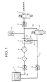
- the device or device shown in Figure 1 provides a system for dosing one within a Catalytic exhaust aftertreatment used Reducing agent.
- Reductant introduced into a mixing chamber, there for Production of an aerosol pressurized with compressed air and introduced into the exhaust gas to be treated.
- Air supply systems and components for catalytic aftertreatment are in themselves known and not the subject of the present application.
- the present application deals with the Reductant delivery system.
- An example is in the following representation as a reducing agent a urea-water solution used, which for simplicity also is called urea.
- 1 denotes a urea tank from which a urea-water solution over a Urea line 1a with a check valve 2 and one Filter 3 designed as a filter screen from a feed pump 4 sucked in and via a second urea line 1b a pressure regulator or damper 5 and another Check valve 6 to a metering or injection valve a (not shown) mixing chamber is promoted.
- the Dosing valve 7 doses the required urea-water solution into a mixing room of the mixing chamber.
- a any overflow quantity that occurs is above the Pressure regulator 5 and a check valve 8 through a Return line 1c can be returned to the urea tank 1.
- the pressure prevailing in the reducing agent line 1b is detectable by means of a pressure sensor 9 and it can Pressure fluctuations are corrected (injection quantity correction).
- the vent valve 10 can be controlled in a clocked manner.
- vent valve 10 By appropriate activation of the vent valve 10 is a venting of the metering valve 7 supplied Feasible urea, overall compared to one conventional solutions leads to higher dosing accuracy. On the back pressure acting on the pump 4 Urea cycle can be compared to conventional solutions can be reduced, causing the pump 4 to be relatively low Pump power can be started. That is, through Opening of the line 1d acting as a bypass appropriate control of the vent valve 10 can a faster than conventional solutions Start of dosing with a longer service life of the Systems are guaranteed.
- the vent valve 10 which is also within the Mixing chamber of the urea metering system can be arranged control logic (not shown) driven. By opening the vent valve 10, as already described, the back pressure in the system. The Counterpressure can therefore be overcome more easily by the pump 4 be, resulting in a lower power consumption and a lower overall performance of the pump 4 results.
- the Vent valve 10 can be used during various Operating states of an engine or a catalytic Exhaust gas aftertreatment are actuated, for example not only during a start-up cycle, but also during the Operation, and so can a dynamic ventilation guarantee.
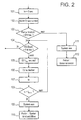
- FIG. 2 shows a start strategy (first start-up) of the Dosing system according to the invention shown.
- Step 101 becomes one to initialize the strategy Start time ta set.
- step 102 During a subsequent step 102 takes place during a time twait2, if necessary, a review of the Components of the system on their functionality (For example, controllability through control logic). It is then determined in a step 103 whether the Speed of pump 4 exceeds a minimum value RPMmin or not. If this is the case, in a step 104 determined whether the pressure in the urea line 1b a adjustable system pressure, which is sufficient for a normal functioning of the urea dosing system viewed, reached or not (Druck Pok). is this pressure reaches Pok, the flowchart branches to a flow chart of a normal, not shown here Functional sequence.
- a step 103 determines whether the pressure in the urea line 1b a adjustable system pressure, which is sufficient for a normal functioning of the urea dosing system viewed, reached or not (Druck Pok). is this pressure reaches Pok, the flowchart branches to a flow chart of a normal, not shown here Functional sequence.
- the vent valve 10 in the flow charts of figures 2 to 4 referred to as EV
- the valve 10 is closed again.
- the opening and closing of the valve 10 serves to vent the line 1b. It is assumed here that too low a pressure in the urea line 1b is due to the presence of air bubbles. Opening and then closing the valve 10 initially leads to a further drop in the pressure, but at the same time to a venting, according to which a higher pressure in the urea line 1 a can in principle be set.
- a pressure build-up time ta is first waited for in a step 107.
- the pressure build-up time ta is incrementally extended until a desired system pressure is reached.
- the time ta for which the desired system pressure or pressure is established in the urea line 1a is compared in a step 108 with a preset time t Def2 . If it is determined that the pressure build-up time ta is less than this time t Def2 , the process branches back to step 104, in which it is again determined whether the pressure in line 1b is greater than the value Pok. If this is the case, the aforementioned branching to the usual control strategy takes place.
- step 108 if it is determined in step 108 that the pressure build-up time ta is greater than the time t Def2 , it is determined in step 109 that the ventilation system (valve 10) is switched off, and in step 110 an error in the system in the sense of found that it cannot be vented.
- step 103 If it is determined in step 103 described above, that the pump speed of pump 4 is RPMmin falls below, a branch is made to a step 111, in which it is found that the The urea dosing system is switched off altogether. In a subsequent step 112 is for a motor defect recognized.
- FIG. 3 shows a flow chart to illustrate dynamic venting during normal operation of the urea metering system.
- a step 201 it is first determined in a step 201 whether the pressure is urea or smaller than a threshold value P limit not. If the urea pressure is not less than this limit value, a decision is made in a step 202 that no ventilation is necessary, ie a ventilation pressure can be set to zero.
- a necessary ventilation pressure P Ent exceeds a ventilation pressure limit value P EntGrenz . If this limit value is exceeded, that is to say venting is necessary with an excessive reduction in pressure, an error is recognized in step 206 to the effect that the system cannot be vented.
- step 205 of this necessary ventilation pressure P Ent is determined and subsequently branch back to step 201 (possibly taking into account a pressure build-up time) in turn determined whether the urea compressed the limit value P limit below or not.
- Figure 4 shows a start-up strategy shown, for example, each time the engine is started is feasible.
- Strategies for Control of a compressed air system which with the Urea system interacts to produce an aerosol, as well as a heating system.
- Heating strategy should be noted that commonly used Urea solutions at temperatures around -11 ° Celsius freeze so that a below this temperature Control of the heating system is necessary.
- a step 301 the metering valve 7 is switched off, In a subsequent step 302, the pump 4 switched off.
- Compressed air is in a step 303 is turned on and in a step 304 a zero point is reached defined for a pressure build-up time.
- a preset limit for example 1 bar, exceeds zero points with regard to a heating time and a drive time of the vent valve 10 (Step 309).
- step 305 it is determined in a step 306 whether or not the time t DL for building up the desired pressure exceeds a limit value t DL limit. If this limit is exceeded, it is determined that there is no compressed air (step 308). If the time t DL does not exceed the limit value, the time t D1 is increased by one increment (t DL +) in a step 307, and it is again determined in step 305 whether the pressure exceeds the preset value.
- step 309 a drive time for the vent valve 10 and the heating system are set to zero.
- a presettable time is waited for during a waiting time t wait1 .
- a subsequent step 311 it is determined whether the system or the urea tank is too cold or not. If this is the case, the heating system is activated and it is determined in step 322 whether or not the required heating time t heating exceeds a presettable limit time t heating limit. If this limit is exceeded, it is recognized that the heater is not working (step 323). If the time t heating limit has not yet been reached, the heating time is increased by one increment (t heating +), after which the system branches back to steps 310 and 311.
- step 311 If it is determined in step 311 that the urea tank or the system is at a sufficient temperature, the start-up strategy for the heating system is completed and the system branches to a step 312 in which it is determined whether the urea pressure is below a minimum value HD min or Not. If this is the case, it is determined in a step 317 whether or not the triggering time of the vent valve exceeds a limit value t EVGrenz . If this is the case, then in a step 320 it is recognized that the vent valve 10 is defective. If this is not the case, the vent valve is opened in a step 318 over a time interval t Evauf . In a subsequent step 319, the activation time t EV is increased by one increment (t EV +), whereupon the system branches back to step 312.
- step 312 if it is recognized in step 312 that the urea pressure is less than the minimum pressure HD min , a check is carried out in step 313 as to whether the urea tank is empty or not. If this is the case, an empty tank is recognized in a step 324. However, if this is not the case, the pump 4 is switched on in a step 314, whereupon the start strategy already described is started in a step 305 and the normal operation of the system is then carried out (step 316).
Landscapes
- Engineering & Computer Science (AREA)
- Chemical & Material Sciences (AREA)
- Chemical Kinetics & Catalysis (AREA)
- Health & Medical Sciences (AREA)
- Environmental & Geological Engineering (AREA)
- Biomedical Technology (AREA)
- Analytical Chemistry (AREA)
- General Chemical & Material Sciences (AREA)
- Oil, Petroleum & Natural Gas (AREA)
- Combustion & Propulsion (AREA)
- Toxicology (AREA)
- Mechanical Engineering (AREA)
- General Engineering & Computer Science (AREA)
- Exhaust Gas After Treatment (AREA)
Abstract
Claims (2)
- Procédé de dosage d'un agent réducteur utilisé pour le traitement catalytique des gaz d'échappement selon lequel on fournit l'agent réducteùr par un système de conduite (1a, 1b) à une installation de mélange de dosage (7),
caractérisé en ce qu'
on surveille la pression (9) régnant dans un système de conduite (1a, 1b) comportant une pompe (4) et au cas où la pression est inférieure à un seuil (Pok, Plim evac), on ouvre une soupape d'évacuation (10) (105, 204) pour que le système de conduite du côté de la pompe (4) relié à l'installation de dosage ou de mélange (7) soit relié à un circuit d'évacuation (1c, 1d) qui continue tout d'abord de diminuer la pression et évacue le système de conduite (1a, 1b). - Procédé selon la revendication 1,
caractérisé en ce que
le circuit d'évacuation comporte une soupape d'évacuation (10) commandée en cadence et qui est actionnée pour modifier la pression dans le système de conduite.
Applications Claiming Priority (3)
| Application Number | Priority Date | Filing Date | Title |
|---|---|---|---|
| DE19947197A DE19947197A1 (de) | 1999-10-01 | 1999-10-01 | Vorrichtung und Verfahren zur Dosierung eines Reduktionsmittels |
| DE19947197 | 1999-10-01 | ||
| PCT/DE2000/003299 WO2001025600A1 (fr) | 1999-10-01 | 2000-09-22 | Dispositif et procede pour doser un agent de reduction |
Publications (2)
| Publication Number | Publication Date |
|---|---|
| EP1222370A1 EP1222370A1 (fr) | 2002-07-17 |
| EP1222370B1 true EP1222370B1 (fr) | 2003-12-03 |
Family
ID=7924068
Family Applications (1)
| Application Number | Title | Priority Date | Filing Date |
|---|---|---|---|
| EP00975784A Expired - Lifetime EP1222370B1 (fr) | 1999-10-01 | 2000-09-22 | Dispositif et procede pour doser un agent de reduction |
Country Status (5)
| Country | Link |
|---|---|
| EP (1) | EP1222370B1 (fr) |
| JP (1) | JP4460811B2 (fr) |
| KR (1) | KR100697545B1 (fr) |
| DE (2) | DE19947197A1 (fr) |
| WO (1) | WO2001025600A1 (fr) |
Cited By (2)
| Publication number | Priority date | Publication date | Assignee | Title |
|---|---|---|---|---|
| US8256209B2 (en) | 2005-07-26 | 2012-09-04 | Robert Bosch Gmbh | Device and method for regenerating a particulate filter |
| EP2660436A1 (fr) | 2012-05-03 | 2013-11-06 | Emitec France S.A.S. | Procédé de purge d'air d'une unité d'alimentation d'un additif liquide |
Families Citing this family (28)
| Publication number | Priority date | Publication date | Assignee | Title |
|---|---|---|---|---|
| DE10047516A1 (de) | 2000-09-22 | 2002-04-18 | Bosch Gmbh Robert | Verfahren und Vorrichtung zur Dosierung eines Reduktionsmittels zur Entfernung von Stickoxiden aus Abgasen |
| KR100392606B1 (ko) * | 2001-03-24 | 2003-07-23 | 삼성광주전자 주식회사 | 진공청소기의 사이클론 집진장치 |
| DE20116379U1 (de) | 2001-10-05 | 2002-01-03 | PUREM Abgassysteme GmbH & Co. KG, 58706 Menden | Vorrichtung zum Dosieren eines gasförmigen Reduktionsmittels |
| AT500849B8 (de) * | 2004-11-15 | 2007-02-15 | Pankl Emission Control Systems | Harnstoffdosiervorrichtung |
| AT501091B1 (de) * | 2004-11-15 | 2006-12-15 | Pankl Emission Control Systems | Abgasreinigungsvorrichtung |
| DE102004061259B4 (de) * | 2004-12-20 | 2016-12-15 | Robert Bosch Gmbh | Verfahren und Vorrichtung zur Auftauerkennung in einer Reagenzmitteldosiereinrichtung eines SCR-Katalysators insbesondere einer Brennkraftmaschine |
| EP1676628B1 (fr) | 2004-12-30 | 2009-10-07 | Grundfos NoNox a/s | Unité de pompe de dosage |
| DE502004005576D1 (de) | 2004-12-30 | 2008-01-03 | Grundfos Nonox As | Vorrichtung zur Erzeugung eines Reduktionsmittel-Luft-Gemisches |
| DE502004003566D1 (de) * | 2004-12-30 | 2007-05-31 | Grundfos Management As | Dosierpumpenaggregat |
| EP2047076A1 (fr) * | 2006-07-13 | 2009-04-15 | Inergy Automotive Systems Research (Société A.) | Système et procédé permettant de stocker un additif et de l'injecter dans les gaz d'échappement d'un moteur |
| DE102007033470B4 (de) * | 2007-07-18 | 2012-10-25 | Continental Automotive Gmbh | Vorrichtung und Verfahren zur Dosierung eines Reduktionsmittels in einen Abgastrakt eines Fahrzeugs |
| DE102007044403B4 (de) * | 2007-09-18 | 2011-04-28 | Continental Automotive Gmbh | Vorrichtung zum Einbringen einer Reduktionsmittelflüssigkeit in ein Abgas einer Verbrennungsanlage |
| DE102009023325B4 (de) * | 2008-12-10 | 2012-01-26 | Continental Automotive Gmbh | Verfahren zur Adaption der Injektionsmittelzufuhr in einem Injektionssystem |
| DE102009035940C5 (de) * | 2009-08-03 | 2017-04-20 | Cummins Ltd. | SCR-Abgasnachbehandlungseinrichtung |
| DE102009037564B4 (de) * | 2009-08-14 | 2013-08-29 | Continental Automotive Gmbh | Vorrichtung und Verfahren zur Dosierung eines Reduktionsmittels in einen Abgastrakt einer Brennkraftmaschine |
| DE102009056181A1 (de) * | 2009-11-27 | 2011-06-01 | Emitec Gesellschaft Für Emissionstechnologie Mbh | Verfahren zum Betrieb einer Fördervorrichtung für ein Reduktionsmittel |
| DE102010004201A1 (de) | 2010-01-08 | 2011-07-14 | Emitec Gesellschaft für Emissionstechnologie mbH, 53797 | Verfahren zum Betrieb einer Fördervorrichtung für ein Reduktionsmittel |
| SE536920C2 (sv) | 2010-06-21 | 2014-10-28 | Scania Cv Ab | SCR-system för avgasrening och förfarande för kylning av endoseringsenhet vid ett sådant SCR-system |
| SE535632C2 (sv) * | 2010-06-21 | 2012-10-23 | Scania Cv Ab | Förfarande vid förekomst av luft i vätsketillförsel vid ett SCR-system och motsvarande SCR-system |
| SE535631C2 (sv) * | 2010-06-21 | 2012-10-23 | Scania Cv Ab | Förfarande vid förekomst av luft i ett HC-doseringssystem och motsvarande HC-doseringssystem |
| AT510671B1 (de) * | 2010-10-29 | 2013-11-15 | Hirtenberger Ag | Vorrichtung zur selektiven katalytischen reduktion von stickoxiden in einem abgastrakt eines kraftfahrzeuges |
| DE102011003327A1 (de) * | 2011-01-28 | 2012-08-02 | Robert Bosch Gmbh | Verfahren zur Erfassung des Beladungszustandes eines Filters in einem SCR-Dosiersystem |
| US8881507B2 (en) * | 2011-08-22 | 2014-11-11 | Mi Yan | Air driven reductant delivery system |
| FR2979948B1 (fr) * | 2011-09-14 | 2015-02-20 | Peugeot Citroen Automobiles Sa | Procede d'amorcage de l'injection dosee d'un agent liquide dans un ensemble et systeme d'injection mettant en œuvre un tel procede |
| DE102012002059A1 (de) * | 2012-02-03 | 2013-08-08 | Emitec Gesellschaft Für Emissionstechnologie Mbh | Verfahren zum Betrieb einer Dosiervorrichtung |
| CN105673154B (zh) | 2014-11-21 | 2019-11-08 | 天纳克(苏州)排放系统有限公司 | 共轨、该共轨的应用、尿素喷射系统及其控制方法 |
| US20190048793A1 (en) * | 2016-02-09 | 2019-02-14 | Kautex Textron Gmbh & Co. Kg | System for storing and delivering an auxiliary liquid to an internal combustion engine of a motor vehicle or to parts of the internal combustion engine of the motor vehicle |
| CN109630894B (zh) * | 2018-12-21 | 2020-06-26 | 云南大红山管道有限公司 | 长距离管道自动补排气装置及操作方法 |
Family Cites Families (4)
| Publication number | Priority date | Publication date | Assignee | Title |
|---|---|---|---|---|
| DE3230608A1 (de) * | 1982-08-18 | 1984-02-23 | Volkswagenwerk Ag, 3180 Wolfsburg | Verfahren zur reinigung eines russfilters im abgassystem einer brennkraftmaschine |
| JPH06200857A (ja) * | 1993-01-08 | 1994-07-19 | Fuji Heavy Ind Ltd | 高圧噴射式エンジンの燃料圧力制御方法 |
| DE59507350D1 (de) * | 1994-09-13 | 2000-01-05 | Siemens Ag | Verfahren und einrichtung zum einbringen von flüssigkeit in eine abgasreinigungsvorrichtung |
| DE4441261A1 (de) * | 1994-11-19 | 1996-05-23 | Bosch Gmbh Robert | Einrichtung zum Nachbehandeln von Abgasen einer Brennkraftmaschine |
-
1999
- 1999-10-01 DE DE19947197A patent/DE19947197A1/de not_active Withdrawn
-
2000
- 2000-09-22 DE DE50004671T patent/DE50004671D1/de not_active Expired - Lifetime
- 2000-09-22 EP EP00975784A patent/EP1222370B1/fr not_active Expired - Lifetime
- 2000-09-22 JP JP2001528310A patent/JP4460811B2/ja not_active Expired - Fee Related
- 2000-09-22 KR KR1020027004015A patent/KR100697545B1/ko not_active IP Right Cessation
- 2000-09-22 WO PCT/DE2000/003299 patent/WO2001025600A1/fr active IP Right Grant
Cited By (3)
| Publication number | Priority date | Publication date | Assignee | Title |
|---|---|---|---|---|
| US8256209B2 (en) | 2005-07-26 | 2012-09-04 | Robert Bosch Gmbh | Device and method for regenerating a particulate filter |
| CN101233303B (zh) * | 2005-07-26 | 2012-10-17 | 罗伯特·博世有限公司 | 用于使颗粒滤清器再生的装置和方法 |
| EP2660436A1 (fr) | 2012-05-03 | 2013-11-06 | Emitec France S.A.S. | Procédé de purge d'air d'une unité d'alimentation d'un additif liquide |
Also Published As
| Publication number | Publication date |
|---|---|
| JP4460811B2 (ja) | 2010-05-12 |
| WO2001025600A1 (fr) | 2001-04-12 |
| DE19947197A1 (de) | 2001-04-12 |
| JP2003511599A (ja) | 2003-03-25 |
| EP1222370A1 (fr) | 2002-07-17 |
| KR100697545B1 (ko) | 2007-03-21 |
| KR20020034199A (ko) | 2002-05-08 |
| DE50004671D1 (de) | 2004-01-15 |
Similar Documents
| Publication | Publication Date | Title |
|---|---|---|
| EP1222370B1 (fr) | Dispositif et procede pour doser un agent de reduction | |
| DE19914787C2 (de) | Abgasreinigungssystem für einen Verbrennungsmotor | |
| DE19947198B4 (de) | Vorrichtung zum Nachbehandeln von Abgasen einer Brennkraftmaschine | |
| DE102009023325B4 (de) | Verfahren zur Adaption der Injektionsmittelzufuhr in einem Injektionssystem | |
| DE102009026510B4 (de) | Abgasreinigungsvorrichtung für Verbrennungsmotor | |
| DE102006057325B4 (de) | Abgasreinigungsvorrichtung | |
| DE69917990T2 (de) | Vorrichtung zur Abgasreinigung für eine Brennkraftmaschine | |
| DE10346220A1 (de) | Brennkraftmaschine mit Abgasnachbehandlungssystem | |
| EP1761690B1 (fr) | Systeme a soupape de dosage et procede pour faire fonctionner un tel systeme | |
| DE19939807C2 (de) | Verfahren und Vorrichtung zur Abgasnachbehandlung des von einem Verbrennungsmotor erzeugten Abgases und dessen Verwendung | |
| DE102009056181A1 (de) | Verfahren zum Betrieb einer Fördervorrichtung für ein Reduktionsmittel | |
| DE102011016967A1 (de) | Verfahren zum Betrieb einer SCR-Dosiereinheit | |
| WO2009037327A1 (fr) | Procédé de détection de la durée d'ouverture minimale d'un dispositif d'apport d'agent de réduction dans un système de post-traitement des gaz d'échappement comportant un catalyseur scr | |
| DE102008050356A1 (de) | Abgasreinigungseinrichtung für einen Motor | |
| DE102008002326B4 (de) | Zugabemengensteuerungseinrichtung für ein Abgasreinigungsmittel und Abgasemissionssteuerungssystem | |
| DE102004050989A1 (de) | Verfahren zum Betreiben einer Abgasbehandlungsvorrichtung einer Brennkraftmaschine und Vorrichtung zur Durchführung des Verfahrens | |
| DE102006061734A1 (de) | Vorrichtung zum Dosieren eines Reduktionsmittels | |
| EP2310646B1 (fr) | Procédé pour faire fonctionner un système de dosage d'une solution urée-eau | |
| WO2009010569A1 (fr) | Dispositif et procédé pour doser un agent de réduction dans un circuit d'échappement d'un véhicule | |
| DE102008043405B4 (de) | Verfahren zur Prüfung der Funktionsfähigkeit einer Pumpe | |
| EP2313181B1 (fr) | Procédé permettant une addition contrôlée d'un agent de réduction | |
| DE102014213890A1 (de) | Verfahren zum Betreiben einer Reduktionsmitteldosierung eines SCR-Katalysatorsystems sowie entsprechendes SCR-Katalysatorsystem | |
| WO2006050904A1 (fr) | Procede pour faire fonctionner un moteur a combustion interne suralimente | |
| DE102006016447A1 (de) | Verfahren zum Betreiben einer Dosiervorrichtung eines Abgas-Reinigungssystems und Vorrichtung zur Durchführung des Verfahrens | |
| WO2020069550A1 (fr) | Procédé et système de moteur à allumage commandé à post-traitement amélioré des gaz d'échappement par une stratégie de coupure d'alimentation en poussée |
Legal Events
| Date | Code | Title | Description |
|---|---|---|---|
| PUAI | Public reference made under article 153(3) epc to a published international application that has entered the european phase |
Free format text: ORIGINAL CODE: 0009012 |
|
| 17P | Request for examination filed |
Effective date: 20020502 |
|
| AK | Designated contracting states |
Kind code of ref document: A1 Designated state(s): AT BE CH CY DE DK ES FI FR GB GR IE IT LI LU MC NL PT SE |
|
| RIN1 | Information on inventor provided before grant (corrected) |
Inventor name: HUBER, SVEN Inventor name: KRAH, JUERGEN Inventor name: WEISS, ROLAND Inventor name: FRISCH, WALTER Inventor name: SACHSENHOFER, ROBERT Inventor name: MAYER, HANSPETER Inventor name: FOETSCHL, MARKUS Inventor name: OFFENHUBER, MICHAEL |
|
| GRAH | Despatch of communication of intention to grant a patent |
Free format text: ORIGINAL CODE: EPIDOS IGRA |
|
| GRAS | Grant fee paid |
Free format text: ORIGINAL CODE: EPIDOSNIGR3 |
|
| GRAA | (expected) grant |
Free format text: ORIGINAL CODE: 0009210 |
|
| AK | Designated contracting states |
Kind code of ref document: B1 Designated state(s): DE FR GB IT |
|
| REG | Reference to a national code |
Ref country code: GB Ref legal event code: FG4D Free format text: NOT ENGLISH |
|
| REG | Reference to a national code |
Ref country code: IE Ref legal event code: FG4D Free format text: GERMAN |
|
| REF | Corresponds to: |
Ref document number: 50004671 Country of ref document: DE Date of ref document: 20040115 Kind code of ref document: P |
|
| GBT | Gb: translation of ep patent filed (gb section 77(6)(a)/1977) |
Effective date: 20040310 |
|
| REG | Reference to a national code |
Ref country code: IE Ref legal event code: FD4D |
|
| ET | Fr: translation filed | ||
| PLBE | No opposition filed within time limit |
Free format text: ORIGINAL CODE: 0009261 |
|
| STAA | Information on the status of an ep patent application or granted ep patent |
Free format text: STATUS: NO OPPOSITION FILED WITHIN TIME LIMIT |
|
| 26N | No opposition filed |
Effective date: 20040906 |
|
| PGFP | Annual fee paid to national office [announced via postgrant information from national office to epo] |
Ref country code: GB Payment date: 20130920 Year of fee payment: 14 |
|
| PGFP | Annual fee paid to national office [announced via postgrant information from national office to epo] |
Ref country code: IT Payment date: 20130924 Year of fee payment: 14 |
|
| GBPC | Gb: european patent ceased through non-payment of renewal fee |
Effective date: 20140922 |
|
| PG25 | Lapsed in a contracting state [announced via postgrant information from national office to epo] |
Ref country code: GB Free format text: LAPSE BECAUSE OF NON-PAYMENT OF DUE FEES Effective date: 20140922 |
|
| PG25 | Lapsed in a contracting state [announced via postgrant information from national office to epo] |
Ref country code: IT Free format text: LAPSE BECAUSE OF NON-PAYMENT OF DUE FEES Effective date: 20140922 |
|
| REG | Reference to a national code |
Ref country code: FR Ref legal event code: PLFP Year of fee payment: 17 |
|
| REG | Reference to a national code |
Ref country code: FR Ref legal event code: PLFP Year of fee payment: 18 |
|
| PGFP | Annual fee paid to national office [announced via postgrant information from national office to epo] |
Ref country code: FR Payment date: 20170925 Year of fee payment: 18 |
|
| PGFP | Annual fee paid to national office [announced via postgrant information from national office to epo] |
Ref country code: DE Payment date: 20171128 Year of fee payment: 18 |
|
| REG | Reference to a national code |
Ref country code: DE Ref legal event code: R119 Ref document number: 50004671 Country of ref document: DE |
|
| PG25 | Lapsed in a contracting state [announced via postgrant information from national office to epo] |
Ref country code: DE Free format text: LAPSE BECAUSE OF NON-PAYMENT OF DUE FEES Effective date: 20190402 |
|
| PG25 | Lapsed in a contracting state [announced via postgrant information from national office to epo] |
Ref country code: FR Free format text: LAPSE BECAUSE OF NON-PAYMENT OF DUE FEES Effective date: 20180930 |