EP1222370B1 - Device and method for metering a reducing agent - Google Patents
Device and method for metering a reducing agent Download PDFInfo
- Publication number
- EP1222370B1 EP1222370B1 EP00975784A EP00975784A EP1222370B1 EP 1222370 B1 EP1222370 B1 EP 1222370B1 EP 00975784 A EP00975784 A EP 00975784A EP 00975784 A EP00975784 A EP 00975784A EP 1222370 B1 EP1222370 B1 EP 1222370B1
- Authority
- EP
- European Patent Office
- Prior art keywords
- pressure
- urea
- reducing agent
- pump
- metering
- Prior art date
- Legal status (The legal status is an assumption and is not a legal conclusion. Google has not performed a legal analysis and makes no representation as to the accuracy of the status listed.)
- Expired - Lifetime
Links
Images


Classifications
-
- B—PERFORMING OPERATIONS; TRANSPORTING
- B01—PHYSICAL OR CHEMICAL PROCESSES OR APPARATUS IN GENERAL
- B01D—SEPARATION
- B01D53/00—Separation of gases or vapours; Recovering vapours of volatile solvents from gases; Chemical or biological purification of waste gases, e.g. engine exhaust gases, smoke, fumes, flue gases, aerosols
- B01D53/34—Chemical or biological purification of waste gases
- B01D53/74—General processes for purification of waste gases; Apparatus or devices specially adapted therefor
- B01D53/86—Catalytic processes
-
- F—MECHANICAL ENGINEERING; LIGHTING; HEATING; WEAPONS; BLASTING
- F01—MACHINES OR ENGINES IN GENERAL; ENGINE PLANTS IN GENERAL; STEAM ENGINES
- F01N—GAS-FLOW SILENCERS OR EXHAUST APPARATUS FOR MACHINES OR ENGINES IN GENERAL; GAS-FLOW SILENCERS OR EXHAUST APPARATUS FOR INTERNAL COMBUSTION ENGINES
- F01N3/00—Exhaust or silencing apparatus having means for purifying, rendering innocuous, or otherwise treating exhaust
- F01N3/08—Exhaust or silencing apparatus having means for purifying, rendering innocuous, or otherwise treating exhaust for rendering innocuous
- F01N3/10—Exhaust or silencing apparatus having means for purifying, rendering innocuous, or otherwise treating exhaust for rendering innocuous by thermal or catalytic conversion of noxious components of exhaust
- F01N3/18—Exhaust or silencing apparatus having means for purifying, rendering innocuous, or otherwise treating exhaust for rendering innocuous by thermal or catalytic conversion of noxious components of exhaust characterised by methods of operation; Control
- F01N3/20—Exhaust or silencing apparatus having means for purifying, rendering innocuous, or otherwise treating exhaust for rendering innocuous by thermal or catalytic conversion of noxious components of exhaust characterised by methods of operation; Control specially adapted for catalytic conversion ; Methods of operation or control of catalytic converters
- F01N3/2066—Selective catalytic reduction [SCR]
-
- B—PERFORMING OPERATIONS; TRANSPORTING
- B01—PHYSICAL OR CHEMICAL PROCESSES OR APPARATUS IN GENERAL
- B01D—SEPARATION
- B01D53/00—Separation of gases or vapours; Recovering vapours of volatile solvents from gases; Chemical or biological purification of waste gases, e.g. engine exhaust gases, smoke, fumes, flue gases, aerosols
- B01D53/34—Chemical or biological purification of waste gases
- B01D53/92—Chemical or biological purification of waste gases of engine exhaust gases
- B01D53/94—Chemical or biological purification of waste gases of engine exhaust gases by catalytic processes
- B01D53/9495—Controlling the catalytic process
-
- F—MECHANICAL ENGINEERING; LIGHTING; HEATING; WEAPONS; BLASTING
- F01—MACHINES OR ENGINES IN GENERAL; ENGINE PLANTS IN GENERAL; STEAM ENGINES
- F01N—GAS-FLOW SILENCERS OR EXHAUST APPARATUS FOR MACHINES OR ENGINES IN GENERAL; GAS-FLOW SILENCERS OR EXHAUST APPARATUS FOR INTERNAL COMBUSTION ENGINES
- F01N2610/00—Adding substances to exhaust gases
- F01N2610/02—Adding substances to exhaust gases the substance being ammonia or urea
-
- F—MECHANICAL ENGINEERING; LIGHTING; HEATING; WEAPONS; BLASTING
- F01—MACHINES OR ENGINES IN GENERAL; ENGINE PLANTS IN GENERAL; STEAM ENGINES
- F01N—GAS-FLOW SILENCERS OR EXHAUST APPARATUS FOR MACHINES OR ENGINES IN GENERAL; GAS-FLOW SILENCERS OR EXHAUST APPARATUS FOR INTERNAL COMBUSTION ENGINES
- F01N2610/00—Adding substances to exhaust gases
- F01N2610/08—Adding substances to exhaust gases with prior mixing of the substances with a gas, e.g. air
-
- F—MECHANICAL ENGINEERING; LIGHTING; HEATING; WEAPONS; BLASTING
- F01—MACHINES OR ENGINES IN GENERAL; ENGINE PLANTS IN GENERAL; STEAM ENGINES
- F01N—GAS-FLOW SILENCERS OR EXHAUST APPARATUS FOR MACHINES OR ENGINES IN GENERAL; GAS-FLOW SILENCERS OR EXHAUST APPARATUS FOR INTERNAL COMBUSTION ENGINES
- F01N2610/00—Adding substances to exhaust gases
- F01N2610/14—Arrangements for the supply of substances, e.g. conduits
- F01N2610/1466—Means for venting air out of conduits or tanks
-
- F—MECHANICAL ENGINEERING; LIGHTING; HEATING; WEAPONS; BLASTING
- F01—MACHINES OR ENGINES IN GENERAL; ENGINE PLANTS IN GENERAL; STEAM ENGINES
- F01N—GAS-FLOW SILENCERS OR EXHAUST APPARATUS FOR MACHINES OR ENGINES IN GENERAL; GAS-FLOW SILENCERS OR EXHAUST APPARATUS FOR INTERNAL COMBUSTION ENGINES
- F01N2610/00—Adding substances to exhaust gases
- F01N2610/14—Arrangements for the supply of substances, e.g. conduits
- F01N2610/1473—Overflow or return means for the substances, e.g. conduits or valves for the return path
-
- Y—GENERAL TAGGING OF NEW TECHNOLOGICAL DEVELOPMENTS; GENERAL TAGGING OF CROSS-SECTIONAL TECHNOLOGIES SPANNING OVER SEVERAL SECTIONS OF THE IPC; TECHNICAL SUBJECTS COVERED BY FORMER USPC CROSS-REFERENCE ART COLLECTIONS [XRACs] AND DIGESTS
- Y02—TECHNOLOGIES OR APPLICATIONS FOR MITIGATION OR ADAPTATION AGAINST CLIMATE CHANGE
- Y02T—CLIMATE CHANGE MITIGATION TECHNOLOGIES RELATED TO TRANSPORTATION
- Y02T10/00—Road transport of goods or passengers
- Y02T10/10—Internal combustion engine [ICE] based vehicles
- Y02T10/12—Improving ICE efficiencies
Definitions
- the present invention relates to a method for Dosage one as part of a catalytic Exhaust gas treatment used reducing agent, in particular a urea or a urea-water solution, according to the preamble of claim 1.
- reduction catalysts In order to achieve a reduction in NO x components in exhaust gases, reduction catalysts have been developed, especially for diesel engines, which are usually divided into so-called SCR (selective catalytic reduction) catalysts with a urea metering system and storage catalysts.
- SCR catalysts selective catalytic reduction
- storage catalysts are regenerated with hydrocarbons of the internal combustion engine fuel carried in so-called exhaust gas fat phases.
- a system is known from EP-A-0381236 which is used to remove nitrogen oxides in exhaust gases Ammonia metered in as a reducing agent from a diesel engine. In this system there is also a Turbocharger provided, which lowers the pressure of the exhaust gas. A urea-water solution used is metered in using compressed air.
- DE-A-44 41 261 describes a device for the aftertreatment of exhaust gases Internal combustion engine known, in which the performance of the catalyst via a metering device should be improved.
- the metering device is a small-volume metering displacement pump formed on a cylindrical body of revolution a thread in the form of a groove has, in order to change the delivery rate of the rotating body a thread in the form has a groove, the rotary body with variable to change the delivery rate Speed is driven.
- the reducing agent is added to the exhaust system preferably dependent on map, i.e. depending on the amount and / or composition of the Exhaust gas.
- US 5 884 475 A describes a method for blowing a line free Exhaust gas treatment arrangement by means of compressed air.
- a conventional reducing agent line system with an additional controllable or regulable Form ventilation circuit.
- a ventilation circuit enables an active one Ventilation of the reducing agent line system and thus, for example, faster start-up a pump.
- the controllable ventilation circuit expediently has a clocked control Vent valve open. On such a vent valve is simple controllable and proves to be robust and in practice reliable component.
- vent valve is expediently a 2/2-way valve educated.
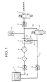
- the device or device shown in Figure 1 provides a system for dosing one within a Catalytic exhaust aftertreatment used Reducing agent.
- Reductant introduced into a mixing chamber, there for Production of an aerosol pressurized with compressed air and introduced into the exhaust gas to be treated.
- Air supply systems and components for catalytic aftertreatment are in themselves known and not the subject of the present application.
- the present application deals with the Reductant delivery system.
- An example is in the following representation as a reducing agent a urea-water solution used, which for simplicity also is called urea.
- 1 denotes a urea tank from which a urea-water solution over a Urea line 1a with a check valve 2 and one Filter 3 designed as a filter screen from a feed pump 4 sucked in and via a second urea line 1b a pressure regulator or damper 5 and another Check valve 6 to a metering or injection valve a (not shown) mixing chamber is promoted.
- the Dosing valve 7 doses the required urea-water solution into a mixing room of the mixing chamber.
- a any overflow quantity that occurs is above the Pressure regulator 5 and a check valve 8 through a Return line 1c can be returned to the urea tank 1.
- the pressure prevailing in the reducing agent line 1b is detectable by means of a pressure sensor 9 and it can Pressure fluctuations are corrected (injection quantity correction).
- the vent valve 10 can be controlled in a clocked manner.
- vent valve 10 By appropriate activation of the vent valve 10 is a venting of the metering valve 7 supplied Feasible urea, overall compared to one conventional solutions leads to higher dosing accuracy. On the back pressure acting on the pump 4 Urea cycle can be compared to conventional solutions can be reduced, causing the pump 4 to be relatively low Pump power can be started. That is, through Opening of the line 1d acting as a bypass appropriate control of the vent valve 10 can a faster than conventional solutions Start of dosing with a longer service life of the Systems are guaranteed.
- the vent valve 10 which is also within the Mixing chamber of the urea metering system can be arranged control logic (not shown) driven. By opening the vent valve 10, as already described, the back pressure in the system. The Counterpressure can therefore be overcome more easily by the pump 4 be, resulting in a lower power consumption and a lower overall performance of the pump 4 results.
- the Vent valve 10 can be used during various Operating states of an engine or a catalytic Exhaust gas aftertreatment are actuated, for example not only during a start-up cycle, but also during the Operation, and so can a dynamic ventilation guarantee.
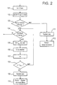
- FIG. 2 shows a start strategy (first start-up) of the Dosing system according to the invention shown.
- Step 101 becomes one to initialize the strategy Start time ta set.
- step 102 During a subsequent step 102 takes place during a time twait2, if necessary, a review of the Components of the system on their functionality (For example, controllability through control logic). It is then determined in a step 103 whether the Speed of pump 4 exceeds a minimum value RPMmin or not. If this is the case, in a step 104 determined whether the pressure in the urea line 1b a adjustable system pressure, which is sufficient for a normal functioning of the urea dosing system viewed, reached or not (Druck Pok). is this pressure reaches Pok, the flowchart branches to a flow chart of a normal, not shown here Functional sequence.
- a step 103 determines whether the pressure in the urea line 1b a adjustable system pressure, which is sufficient for a normal functioning of the urea dosing system viewed, reached or not (Druck Pok). is this pressure reaches Pok, the flowchart branches to a flow chart of a normal, not shown here Functional sequence.
- the vent valve 10 in the flow charts of figures 2 to 4 referred to as EV
- the valve 10 is closed again.
- the opening and closing of the valve 10 serves to vent the line 1b. It is assumed here that too low a pressure in the urea line 1b is due to the presence of air bubbles. Opening and then closing the valve 10 initially leads to a further drop in the pressure, but at the same time to a venting, according to which a higher pressure in the urea line 1 a can in principle be set.
- a pressure build-up time ta is first waited for in a step 107.
- the pressure build-up time ta is incrementally extended until a desired system pressure is reached.
- the time ta for which the desired system pressure or pressure is established in the urea line 1a is compared in a step 108 with a preset time t Def2 . If it is determined that the pressure build-up time ta is less than this time t Def2 , the process branches back to step 104, in which it is again determined whether the pressure in line 1b is greater than the value Pok. If this is the case, the aforementioned branching to the usual control strategy takes place.
- step 108 if it is determined in step 108 that the pressure build-up time ta is greater than the time t Def2 , it is determined in step 109 that the ventilation system (valve 10) is switched off, and in step 110 an error in the system in the sense of found that it cannot be vented.
- step 103 If it is determined in step 103 described above, that the pump speed of pump 4 is RPMmin falls below, a branch is made to a step 111, in which it is found that the The urea dosing system is switched off altogether. In a subsequent step 112 is for a motor defect recognized.
- FIG. 3 shows a flow chart to illustrate dynamic venting during normal operation of the urea metering system.
- a step 201 it is first determined in a step 201 whether the pressure is urea or smaller than a threshold value P limit not. If the urea pressure is not less than this limit value, a decision is made in a step 202 that no ventilation is necessary, ie a ventilation pressure can be set to zero.
- a necessary ventilation pressure P Ent exceeds a ventilation pressure limit value P EntGrenz . If this limit value is exceeded, that is to say venting is necessary with an excessive reduction in pressure, an error is recognized in step 206 to the effect that the system cannot be vented.
- step 205 of this necessary ventilation pressure P Ent is determined and subsequently branch back to step 201 (possibly taking into account a pressure build-up time) in turn determined whether the urea compressed the limit value P limit below or not.
- Figure 4 shows a start-up strategy shown, for example, each time the engine is started is feasible.
- Strategies for Control of a compressed air system which with the Urea system interacts to produce an aerosol, as well as a heating system.
- Heating strategy should be noted that commonly used Urea solutions at temperatures around -11 ° Celsius freeze so that a below this temperature Control of the heating system is necessary.
- a step 301 the metering valve 7 is switched off, In a subsequent step 302, the pump 4 switched off.
- Compressed air is in a step 303 is turned on and in a step 304 a zero point is reached defined for a pressure build-up time.
- a preset limit for example 1 bar, exceeds zero points with regard to a heating time and a drive time of the vent valve 10 (Step 309).
- step 305 it is determined in a step 306 whether or not the time t DL for building up the desired pressure exceeds a limit value t DL limit. If this limit is exceeded, it is determined that there is no compressed air (step 308). If the time t DL does not exceed the limit value, the time t D1 is increased by one increment (t DL +) in a step 307, and it is again determined in step 305 whether the pressure exceeds the preset value.
- step 309 a drive time for the vent valve 10 and the heating system are set to zero.
- a presettable time is waited for during a waiting time t wait1 .
- a subsequent step 311 it is determined whether the system or the urea tank is too cold or not. If this is the case, the heating system is activated and it is determined in step 322 whether or not the required heating time t heating exceeds a presettable limit time t heating limit. If this limit is exceeded, it is recognized that the heater is not working (step 323). If the time t heating limit has not yet been reached, the heating time is increased by one increment (t heating +), after which the system branches back to steps 310 and 311.
- step 311 If it is determined in step 311 that the urea tank or the system is at a sufficient temperature, the start-up strategy for the heating system is completed and the system branches to a step 312 in which it is determined whether the urea pressure is below a minimum value HD min or Not. If this is the case, it is determined in a step 317 whether or not the triggering time of the vent valve exceeds a limit value t EVGrenz . If this is the case, then in a step 320 it is recognized that the vent valve 10 is defective. If this is not the case, the vent valve is opened in a step 318 over a time interval t Evauf . In a subsequent step 319, the activation time t EV is increased by one increment (t EV +), whereupon the system branches back to step 312.
- step 312 if it is recognized in step 312 that the urea pressure is less than the minimum pressure HD min , a check is carried out in step 313 as to whether the urea tank is empty or not. If this is the case, an empty tank is recognized in a step 324. However, if this is not the case, the pump 4 is switched on in a step 314, whereupon the start strategy already described is started in a step 305 and the normal operation of the system is then carried out (step 316).
Landscapes
- Engineering & Computer Science (AREA)
- Chemical & Material Sciences (AREA)
- Chemical Kinetics & Catalysis (AREA)
- Health & Medical Sciences (AREA)
- Environmental & Geological Engineering (AREA)
- Biomedical Technology (AREA)
- Analytical Chemistry (AREA)
- General Chemical & Material Sciences (AREA)
- Oil, Petroleum & Natural Gas (AREA)
- Combustion & Propulsion (AREA)
- Toxicology (AREA)
- Mechanical Engineering (AREA)
- General Engineering & Computer Science (AREA)
- Exhaust Gas After Treatment (AREA)
Abstract
Description
Die vorliegende Erfindung betrifft ein Verfahren zur
Dosierung eines im Rahmen einer katalytischen
Abgasnachbehandlung verwendeten Reduktionsmittels,
insbesondere eines Harnstoffs bzw. einer Harnstoff-Wasser-Lösung,
nach dem Oberbegriff des Patentanspruchs 1.The present invention relates to a method for
Dosage one as part of a catalytic
Exhaust gas treatment used reducing agent,
in particular a urea or a urea-water solution,
according to the preamble of
Als Folge der in den letzten Jahren stets niedriger anzusetzenden Schadstoffgrenzwerte sind zahlreiche Vorrichtungen und Verfahren zur Nachbehandlung von Abgasen von Brennkraftmaschinen entwickelt worden. Beispielsweise mittels Katalysatorsystemen, welche Harnstoff und/oder Ammoniak als Reduktionsmittel zur NOx-Konvertierung verwenden, sind effiziente Abgasnachbehandlungssysteme zur Verfügung gestellt.As a result of the pollutant limit values, which have been increasingly lower in recent years, numerous devices and methods for the aftertreatment of exhaust gases from internal combustion engines have been developed. Efficient exhaust gas aftertreatment systems are made available, for example, by means of catalyst systems which use urea and / or ammonia as a reducing agent for NO x conversion.
Um eine Verminderung von NOx-Bestandteilen in Abgasen zu erzielen, wurden insbesondere für Dieselmotoren Reduktionskatalysatoren entwickelt, die üblicherweise in sogenannte SCR-Katalysatoren (engl. Selective Catalytic Reduction) mit Harnstoffdosiersystem und Speicherkatalysatoren unterteilt werden. Die sogenannten SCR-Katalysatoren werden mittels einer Harnstoff- und/oder Ammoniakreduktionsmittelzufuhr regeneriert, während die sogenannten Speicherkatalysatoren mit Kohlenwasserstoffen des mitgeführten Brennkraftmaschinen-Brennstoffs in sogenannten Abgasfettphasen regeneriert werden.In order to achieve a reduction in NO x components in exhaust gases, reduction catalysts have been developed, especially for diesel engines, which are usually divided into so-called SCR (selective catalytic reduction) catalysts with a urea metering system and storage catalysts. The so-called SCR catalysts are regenerated by means of a urea and / or ammonia reducing agent supply, while the so-called storage catalysts are regenerated with hydrocarbons of the internal combustion engine fuel carried in so-called exhaust gas fat phases.
Aus der EP-A-0381236 ist ein System bekannt, welches zum Entfernen von Stickoxiden in Abgasen aus einem Dieselmotor Ammoniak als Reduktionsmittel zudosiert. Bei diesem System ist ferner ein Turbolader vorgesehen, welcher den Druck des Abgases senkt. Eine verwendete Harnstoff-Wasser-Lösung wird mittels Druckluft zudosiert.A system is known from EP-A-0381236 which is used to remove nitrogen oxides in exhaust gases Ammonia metered in as a reducing agent from a diesel engine. In this system there is also a Turbocharger provided, which lowers the pressure of the exhaust gas. A urea-water solution used is metered in using compressed air.
Aus der DE-A-44 41 261 ist eine Einrichtung zum Nachbehandeln von Abgasen einer Brennkraftmaschine bekannt, bei welcher die Leistung des Katalysators über eine Dosiereinrichtung verbessert werden soll. Die Dosiereinrichtung ist als Kleinstmengendosier-Verdrängerpumpe ausgebildet, die auf einem zylindrischen Rotationskörper einen Gewindegang in der Form einer Nut aufweist, wobei zur Änderung der Förderleistung der Rotationskörper einen Gewindegang in der Form einer Nut aufweist, wobei zur Änderung der Förderleistung der Rotationskörper mit variabler Drehzahl angetrieben wird. Die Zugabe des Reduktionsmittels in das Abgassystem erfolgt vorzugsweise kennfeldabhängig, d.h. in Abhängigkeit von Menge und/oder Zusammensetzung des Abgases.DE-A-44 41 261 describes a device for the aftertreatment of exhaust gases Internal combustion engine known, in which the performance of the catalyst via a metering device should be improved. The metering device is a small-volume metering displacement pump formed on a cylindrical body of revolution a thread in the form of a groove has, in order to change the delivery rate of the rotating body a thread in the form has a groove, the rotary body with variable to change the delivery rate Speed is driven. The reducing agent is added to the exhaust system preferably dependent on map, i.e. depending on the amount and / or composition of the Exhaust gas.
Die US 5 884 475 A beschreibt ein Verfahren zum Freiblasen einer Leitung einer Abgasnachbehandlungsanordnung mittels Druckluft.US 5 884 475 A describes a method for blowing a line free Exhaust gas treatment arrangement by means of compressed air.
Bei herkömmlichen Dosiersystemen stellt man Dosierungenauigkeiten fest, welche durch Druckschwankungen in dem Reduktionsmittelleitungssystem auftreten, welches einen Reduktionsmitteltank beispielsweise mit einer Mischkammer zur Bildung eines Aerosols verbindet. Aufgabe der Erfindung ist es, einen gegenüber herkömmlichen Dosiersystemen genauere Dosierung von Reduktionsmitteln zu ermöglichen.With conventional dosing systems, dosing inaccuracies are observed, Pressure fluctuations occur in the reducing agent line system, which a reducing agent tank, for example with a mixing chamber to form an aerosol combines. The object of the invention is a more precise compared to conventional metering systems To allow dosing of reducing agents.
Diese Aufgabe wird gelöst durch ein Verfahren mit den Merkmalen des Patentanspruchs 1.This object is achieved by a method having the features of
Es wurde festgestellt, dass die Dosiergenauigkeitsschwankungen durch im Reduktionsmittel auftretende Luftblasen verursacht werden. Es wird daher erfindungsgemäß vorgeschlagen, ein herkömmliches Reduktionsmittel-Leitungssystem mit einem zusätzlichen steuerbaren bzw. regelbaren Entlüftungskreislauf auszubilden. Ein derartiger Entlüftungskreislauf ermöglicht eine aktive Entlüftung des Reduktionsmittel-Leitungssystems und damit beispielsweise eine rascheres Anlaufen einer Pumpe. Ein unkontrolliertes Entlüften über ein Dosier- bzw. Einspritzventil, über welches eine Mischkammer mit Reduktionsmittel beaufschlagt wird, kann vermieden werden. Dadurch, dass ein auf eine Förderpumpe wirkender Gegendruck durch Entlüftung vermindert werden kann, können auch der Pumpenanlauf sowie der Pumpenbetrieb verbessert werden.It was found that the metering accuracy fluctuations due to the reducing agent air bubbles are caused. It is therefore proposed according to the invention, a conventional reducing agent line system with an additional controllable or regulable Form ventilation circuit. Such a ventilation circuit enables an active one Ventilation of the reducing agent line system and thus, for example, faster start-up a pump. An uncontrolled venting via a metering or injection valve, via which one Mixing chamber with reducing agent can be avoided. By having one on a feed pump counter pressure can be reduced by venting, can also Pump start-up and pump operation can be improved.
Vorteilhafte Ausgestaltungen der erfindungsgemäßen Vorrichtung bzw. des erfindungsgemäßen Verfahrens sind Gegenstand des Unteranspruchs.Advantageous embodiments of the device according to the invention or of the invention Procedures are the subject of the subclaim.
Zweckmäßigerweise weist der steuerbare Entlüftungskreislauf ein getaktet ansteuerbares Entlüftungsventil auf. Ein derartiges Entlüftungsventil ist in einfacher Weise ansteuerbar und erweist sich in der Praxis als robustes und zuverlässiges Bauteil.The controllable ventilation circuit expediently has a clocked control Vent valve open. On such a vent valve is simple controllable and proves to be robust and in practice reliable component.
Zweckmäßigerweise ist das Entlüftungsventil als 2/2-Wegeventil ausgebildet.The vent valve is expediently a 2/2-way valve educated.
Bevorzugte Ausgestaltungen der Erfindung werden nun anhand der beigefügten Zeichnung weiter erläutert. In dieser zeigt
Figur 1- eine schematische blockschaltbildartige Ansicht einer bevorzugten Ausführungsform der erfindungsgemäßen Vorrichtung,
Figur 2- ein Flußdiagramm zur Darstellung einer mit der erfindungsgemäßen Vorrichtung durchführbaren Startstrategie,
Figur 3- ein Flußdiagramm einer mit der erfindungsgemäßen Vorrichtung durchführbaren Entlüftungsstrategie, und
- Figur 4
- eine mit der erfindungsgemäßen Vorrichtung durchführbare Anlaufstrategie.
- Figure 1
- 2 shows a schematic block diagram view of a preferred embodiment of the device according to the invention,
- Figure 2
- 2 shows a flowchart to illustrate a start strategy that can be carried out with the device according to the invention
- Figure 3
- a flow diagram of a venting strategy which can be carried out with the device according to the invention, and
- Figure 4
- a start-up strategy that can be carried out with the device according to the invention.
Die in Figur 1 dargestellte Vorrichtung bzw. Vorrichtung stellt ein System zur Dosierung eines im Rahmen einer katalytischen Abgasnachbehandlung verwendeten Reduktionsmittels dar. In derartigen Systemen wird Reduktionsmittel in eine Mischkammer eingeführt, dort zur Herstellung eines Aerosols mit Druckluft beaufschlagt und in das zu behandelnde Abgas eingebracht. Luftzufuhrsysteme und Bauteile zur katalytischen Nachbehandlung sind an sich bekannt und nicht Gegenstand der vorliegenden Anmeldung. Die vorliegende Anmeldung beschäftigt sich mit dem Reduktionsmittel-Zuleitungssystem. Beispielhaft wird in der folgenden Darstellung als Reduktionsmittel eine Harnstoff-Wasser-Lösung verwendet, welche der Einfachheit halber auch als Harnstoff bezeichnet wird.The device or device shown in Figure 1 provides a system for dosing one within a Catalytic exhaust aftertreatment used Reducing agent. In such systems Reductant introduced into a mixing chamber, there for Production of an aerosol pressurized with compressed air and introduced into the exhaust gas to be treated. Air supply systems and components for catalytic aftertreatment are in themselves known and not the subject of the present application. The present application deals with the Reductant delivery system. An example is in the following representation as a reducing agent a urea-water solution used, which for simplicity also is called urea.
In Figur 1 ist mit 1 ein Harnstofftank bezeichnet, aus
welchem eine Harnstoff-Wasser-Lösung über eine
Harnstoffleitung 1a mit einem Rückschlagventil 2 und einen
als Filtersieb ausgeführten Filter 3 von einer Förderpumpe
4 angesaugt und über eine zweite Harnstoffleitung 1b mit
einem Druckregler bzw. -dämpfer 5 sowie einem weiteren
Rückschlagventil 6 zu einem Dosier- bzw. Einspritzventil
einer (nicht dargestellten) Mischkammer gefördert wird. Das
Dosierventil 7 dosiert die erforderliche Harnstoff-Wasser-Lösung
in einen Mischraum der Mischkammer ein. Eine
eventuell auftretende Überströmmenge ist über den
Druckregler 5 und ein Rückschlagventil 8 durch eine
Rücklaufleitung 1c in den Harnstofftank 1 zurückführbar.
Der in der Reduktionsmittelleitung 1b herrschende Druck ist
mittels eines Drucksensors 9 feststellbar und es können
Druckschwankungen korrigiert werden (Einspritzmengenkorrektur).In Figure 1, 1 denotes a urea tank from
which a urea-water solution over a
Urea
Zwischen der Pumpe 4 und dem Dosierventil 7, insbesondere
zwischen dem Druckregler 5 und dem Dosierventil 7, zweigt
eine weitere Harnstoffleitung 1d ab, welche mit einem als
Entlüftungsventil 10 dienenden 2/2-Wegeventil
beaufschlagbar ist. Die Harnstoffleitung 1d mündet in der
bereits erwähnten Rücklaufleitung 1c.Between the pump 4 and the metering valve 7, in particular
between the
Das Entlüftungsventil 10 ist getaktet ansteuerbar. The
Durch entsprechende Ansteuerung des Entlüftungsventils 10
ist eine Entlüftung des dem Dosierventil 7 zugeführten
Harnstoffs durchführbar, was insgesamt zu einer gegenüber
herkömmlichen Lösungen höheren Dosiergenauigkeit führt. Ein
die Pumpe 4 beaufschlagender Gegendruck im
Harnstoffkreislauf kann gegenüber herkömmlichen Lösungen
vermindert werden, wodurch die Pumpe 4 mit relativ geringer
Pumpenleistung angefahren werden kann. Das heißt, durch
Öffnung der als Bypass wirkenden Leitung 1d durch
entsprechende Ansteuerung des Entlüftungsventils 10 kann
ein gegenüber herkömmlichen Lösungen schnellerer
Dosierbeginn bei gleichzeitiger längerer Lebensdauer des
Systems gewährleistet werden.By appropriate activation of the
Das Entlüftungsventil 10, welches auch innerhalb der
Mischkammer des Harnstoff-Dosiersystems angeordnet sein
kann, wird von einer (nicht dargestellten) Steuerlogik
angesteuert. Durch Öffnen des Entlüftungsventils 10 sinkt,
wie bereits beschrieben, der Gegendruck im System. Der
Gegendruck kann daher leichter von der Pumpe 4 überwunden
werden, woraus eine geringere Leistungsaufnahme und eine
niedrigere Gesamtleistung der Pumpe 4 resultiert. Das
Entlüftungsventil 10 kann während verschiedener
Betriebszustände eines Motors bzw. einer katalytischen
Abgasnachbehandlung betätigt werden, beispielsweise nicht
nur während eines Anfahrzyklus, sondern auch während des
Betriebes, und kann so eine dynamische Entlüftung
gewährleisten.The
Bevorzugte Ansteuerstrategien bzw. -verfahren des dargestellten Dosiersystems werden nun anhand der Flußdiagramme der Figuren 2 bis 4 näher erläutert. Preferred control strategies or procedures of the Dispensing systems shown are now based on the Flow charts of Figures 2 to 4 explained in more detail.
In Figur 2 ist eine Startstrategie (Erstanlauf) des
erfindungsgemäßen Dosiersystems dargestellt. In einem
Schritt 101 wird zur Initialisierung der Strategie eine
Startzeit ta festgelegt.FIG. 2 shows a start strategy (first start-up) of the
Dosing system according to the invention shown. In one
Während eines anschließenden Schrittes 102 erfolgt während
einer Zeit twait2 gegebenenfalls eine Überprüfung der
Komponenten des Systems auf ihre Funktionsfähigkeit
(beispielsweise Ansteuerbarkeit durch eine Steuerlogik).
Anschließend wird in einem Schritt 103 festgestellt, ob die
Drehzahl der Pumpe 4 einen Minimalwert RPMmin überschreitet
oder nicht. Ist dies der Fall, wird in einem Schritt 104
festgestellt, ob der Druck in der Harnstoffleitung 1b einen
voreinstellbaren Systemdruck, welcher als ausreichend für
einen normalen Funktionsablauf des Harnstoff-Dosiersystems
angesehen wird, erreicht hat oder nicht (Druck Pok). Ist
dieser Druck Pok erreicht, verzweigt das Flußdiagramm zu
einem hier nicht dargestellten Flußdiagramm eines normalen
Funktionsablaufs.During a
Wird jedoch festgestellt, daß der Druck in der
Harnstoffleitung 1a diesen Druck Pok nicht erreicht, wird
das Entlüftungsventil 10 (in den Flußdiagrammen der Figuren
2 bis 4 als EV bezeichnet) über eine bestimmte Zeit tbetr
geöffnet (Schritt 105). In einem anschließenden Schritt 106
wird das Ventil 10 wieder geschlossen. Das Öffnen und
Schließen des Ventils 10 dient der Entlüftung der Leitung
1b. Es wird hierbei davon ausgegangen, daß ein zu niedriger
Druck in der Harnstoffleitung 1b auf die Anwesenheit von
Luftblasen zurückzuführen ist. Durch Öffnen und
anschließendes Schließen des Ventils 10 kommt es zwar
zunächst zu einem weiteren Absinken des Drucks, jedoch
gleichzeitig zu einer Entlüftung, nach welcher prinzipiell
ein höherer Druck in der Harnstoffleitung 1a einstellbar
ist. Zur Feststellung, ob nach Schließen des Ventils 10 in
dem Schritt 106 ein ausreichender Druck in der
Harnstoffleitung 1a erzeugbar ist, wird zunächst in einem
Schritt 107 eine Druckaufbauzeit ta abgewartet. Die
Druckaufbauzeit ta wird hierbei inkrementell bis zum
Erreichen eines gewünschten Systemdrucks verlängert. Die
Zeit ta, für die sich der gewünschte Systemdruck bzw. Druck
in der Harnstoffleitung 1a einstellt, wird in einem Schritt
108 mit einer voreinstellbaren Zeit tDef2 verglichen. Wird
festgestellt, daß die Druckaufbauzeit ta kleiner als diese
Zeit tDef2 ist, erfolgt eine Rückverzweigung zu Schritt 104,
in welchem wiederum festgestellt wird, ob der Druck in der
Leitung 1b größer als der Wert Pok ist. Ist dies nun der
Fall, erfolgt die schon erwähnte Verzweigung zu der
üblichen Ansteuerstrategie.Is found, however, that the pressure in the
Wird in dem Schritt 108 jedoch festgestellt, daß die
Druckaufbauzeit ta größer als die Zeit tDef2 ist, wird in
einem Schritt 109 festgestellt, daß das Entlüftungssystem
(Ventil 10) ausgeschaltet ist, und in einem Schritt 110 ein
Fehler des Systems in dem Sinne, daß es nicht entlüftbar
ist, festgestellt.However, if it is determined in
Wird in dem oben beschriebenen Schritt 103 festgestellt,
daß die Pumpendrehzahl der Pumpe 4 den Wert RPMmin
unterschreitet, erfolgt eine Verzweigung zu einem Schritt
111, in welchem festgestellt wird, daß das
Harnstoffdosiersystem insgesamt ausgeschaltet ist. In einen
anschließenden Schritt 112 wird auf einen Motordefekt
erkannt.If it is determined in
In Figur 3 ist ein Flußdiagramm zur Darstellung eines
dynamischen Entlüftens während des Normalbetriebs des
Harnstoff-Dosiersystems dargestellt. Hier wird zunächst in
einem Schritt 201 festgestellt, ob der Harnstoffdruck
kleiner als ein Grenzwert PGrenz ist oder nicht. Ist der
Harnstoffdruck nicht kleiner als dieser Grenzwert, wird in
einem Schritt 202 entschieden, daß keine Entlüftung
notwendig ist, d. h. ein Entlüftungsdruck gleich Null
gesetzt werden kann.FIG. 3 shows a flow chart to illustrate dynamic venting during normal operation of the urea metering system. Here, it is first determined in a
Ist der Harnstoffdruck jedoch kleiner als der Grenzwert
PGrenz, wird in einem Schritt 203 festgestellt, ob ein
notwendiger Entlüftungsdruck PEnt einen
Entlüftungsdruckgrenzwert PEntGrenz überschreitet oder nicht.
Wird dieser Grenzwert überschritten, d. h. ist eine
Entlüftung unter allzu starker Druckminderung notwendig,
wird in einem Schritt 206 ein Fehler dahingehend erkannt,
daß das System nicht entlüftbar ist.However, if the urea pressure is less than the limit value P limit , it is determined in a
Wird jedoch festgestellt, daß der notwendige
Entlüftungsdruck oberhalb dieses Grenzwertes liegt, wird
das Entlüftungsventil 10 über einen Zeitraum tBel
aufgesteuert. In einen anschließenden Schritt 205 wird der
hierbei notwendige Entlüftungsdruck PEnt festgestellt und
anschließend unter Rückverzweigung auf Schritt 201
(eventuell unter Berücksichtigung einer Druckaufbauzeit)
wiederum festgestellt, ob der Harnstoffdruck den Grenzwert
PGrenz unterschreitet oder nicht. However, if it is determined that the necessary venting pressure is above this limit value, the venting
In Figur 4 wird schließlich eine Anlaufstrategie dargestellt, welche beispielsweise bei jedem Motorstart durchführbar ist. Hierbei werden auch Strategien zur Ansteuerung eines Druckluftsystems, welches mit dem Harnstoffsystem zur Erzeugung eines Aerosols zusammenwirkt, sowie ein Heizungssystem mit berücksichtigt. Bezüglich der Heizstrategie sei angemerkt, daß üblicherweise verwendete Harnstofflösungen bei Temperaturen um etwa -11°Celsius gefrieren, so daß unterhalb dieser Temperatur eine Ansteuerung des Heizungssystems notwendig ist.Finally, Figure 4 shows a start-up strategy shown, for example, each time the engine is started is feasible. Strategies for Control of a compressed air system, which with the Urea system interacts to produce an aerosol, as well as a heating system. Regarding the Heating strategy should be noted that commonly used Urea solutions at temperatures around -11 ° Celsius freeze so that a below this temperature Control of the heating system is necessary.
In einem Schritt 301 wird das Dosierventil 7 abgeschaltet,
in einem anschließenden Schritt 302 wird die Pumpe 4
ausgeschaltet. Druckluft wird in einem Schritt 303
eingeschaltet, und in einem Schritt 304 wird ein Nullpunkt
für eine Druckaufbauzeit definiert. Wird in einem Schritt
305 festgestellt, daß der Luftdruck des Druckluftsystems
einen voreinstellbaren Grenzwert, beispielsweise 1 bar,
überschreitet, werden Nullpunkte bezüglich einer Heizzeit
und einer Ansteuerzeit des Entlüftungsventils 10 gesetzt
(Schritt 309).In a
Wird in dem Schritt 305 jedoch festgestellt, daß die
Druckluft den voreingestellten Wert nicht überschreitet,
wird in einem Schritt 306 festgestellt, ob die Zeit tDL zum
Aufbau des gewünschten Druckes einen Grenzwert tDLGrenz
überschreitet oder nicht. Ist dieser Grenzwert
überschritten, wird festgestellt, daß keine Druckluft
vorhanden ist (Schritt 308). Überschreitet die Zeit tDL den
Grenzwert nicht, wird in einem Schritt 307 die Zeit tD1 um
ein Inkrement erhöht (tDL+), und in dem Schritt 305
wiederum festgestellt, ob der Druck den voreingestellten
Wert überschreitet.However, if it is determined in
Überschreitet der Druck vor Ablauf der Zeit tDLGrenz den
voreingestellten Wert, verzweigt das System, wie bereits
erwähnt, zu Schritt 309, in welchem eine Ansteuerzeit für
das Entlüftungsventil 10 und das Heizungssystem auf Null
gesetzt werden.If the pressure exceeds the preset value before the time t DL limit , the system branches, as already mentioned, to step 309, in which a drive time for the
In einem anschließenden Schritt 310 wird während einer
Wartezeit twait1 eine voreinstellbare Zeit abgewartet. In
einem anschließenden Schritt 311 wird festgestellt, ob das
System bzw. der Harnstofftank zu kalt ist oder nicht. Ist
dies der Fall, wird das Heizungssystem aktiviert, und in
Schritt 322 festgestellt, ob die notwendige Heizzeit tHeiz
eine voreinstellbare Grenzzeit tHeizGrenz überschreitet oder
nicht. Wird diese Grenze überschritten, wird darauf
erkannt, daß die Heizung- nicht funktioniert (Schritt 323).
Ist die Zeit tHeizGrenz noch nicht erreicht, wird die Heizzeit
um ein Inkrement erhöht (tHeiz+), wonach das System zu den
Schritten 310 und 311 zurückverzweigt. Wird in Schritt 311
festgestellt, daß der Harnstofftank bzw. das System eine
ausreichende Temperatur aufweist, ist die Anlaufstrategie
für das Heizsystem abgeschlossen, und das System verzweigt
zu einem Schritt 312, in welchem festgestellt wird, ob der
Harnstoffdruck einen minimalen Wert HDmin unterschreitet
oder nicht. Ist dies der Fall, wird in einem Schritt 317
festgestellt, ob die Ansteuerzeit des Entlüftungsventils
einen Grenzwert tEVGrenz überschreitet oder nicht. Ist dies
der Fall, wird in einem Schritt 320 darauf erkannt, daß das
Entlüftungsventil 10 defekt ist. Ist dies nicht der Fall,
wird in einem Schritt 318 über ein Zeitintervall tEvauf das
Entlüftungsventil geöffnet. In einem anschließenden Schritt
319 wird die Ansteuerzeit tEV um ein Inkrement erhöht
(tEV+), woraufhin das System zu Schritt 312
zurückverzweigt.In a
Wird in Schritt 312 hingegen erkannt, daß der
Harnstoffdruck kleiner als der minimale Druck HDmin ist,
wird in Schritt 313 überprüft, ob der Harnstofftank leer
ist oder nicht. Ist dies der Fall, wird in einem Schritt
324 auf leeren Tank erkannt. Ist dies jedoch nicht der
Fall, wird in einem Schritt 314 die Pumpe 4 eingeschaltet,
woraufhin in einem Schritt 305 die bereits beschriebene
Startstrategie begonnen wird, und anschließend der normale
Betrieb des Systems durchgeführt wird (Schritt 316).On the other hand, if it is recognized in
Claims (2)
- Method for metering a reducing agent used as part of a catalytic exhaust-gas aftertreatment, the reducing agent being fed via a system of lines (1a, 1b) to a metering (7) and/or mixing device, characterized in that a pressure (9) which prevails in the system of lines (1a, 1b), which includes a pump (4), is monitored, and in that, if the pressure is below a threshold value (Pok; Plimit), a bleed valve (10) can be opened (105; 204), so that the system of lines is connected to a bleed circuit (1c, 1d) on that side of the pump (4) which is connected to the metering (7) and/or mixing device, the pressure is initially reduced further and the system of lines (1a, 1b) is bled.
- Method according to Claim 1, characterized in that the bleed circuit includes a bleed valve (10) which can be controlled cyclically and can be actuated in order to modify the pressure in the system of lines.
Applications Claiming Priority (3)
| Application Number | Priority Date | Filing Date | Title |
|---|---|---|---|
| DE19947197A DE19947197A1 (en) | 1999-10-01 | 1999-10-01 | Device and method for dosing a reducing agent |
| DE19947197 | 1999-10-01 | ||
| PCT/DE2000/003299 WO2001025600A1 (en) | 1999-10-01 | 2000-09-22 | Device and method for metering a reducing agent |
Publications (2)
| Publication Number | Publication Date |
|---|---|
| EP1222370A1 EP1222370A1 (en) | 2002-07-17 |
| EP1222370B1 true EP1222370B1 (en) | 2003-12-03 |
Family
ID=7924068
Family Applications (1)
| Application Number | Title | Priority Date | Filing Date |
|---|---|---|---|
| EP00975784A Expired - Lifetime EP1222370B1 (en) | 1999-10-01 | 2000-09-22 | Device and method for metering a reducing agent |
Country Status (5)
| Country | Link |
|---|---|
| EP (1) | EP1222370B1 (en) |
| JP (1) | JP4460811B2 (en) |
| KR (1) | KR100697545B1 (en) |
| DE (2) | DE19947197A1 (en) |
| WO (1) | WO2001025600A1 (en) |
Cited By (2)
| Publication number | Priority date | Publication date | Assignee | Title |
|---|---|---|---|---|
| US8256209B2 (en) | 2005-07-26 | 2012-09-04 | Robert Bosch Gmbh | Device and method for regenerating a particulate filter |
| EP2660436A1 (en) | 2012-05-03 | 2013-11-06 | Emitec France S.A.S. | Method for deaerating a liquid additive supply unit |
Families Citing this family (28)
| Publication number | Priority date | Publication date | Assignee | Title |
|---|---|---|---|---|
| DE10047516A1 (en) * | 2000-09-22 | 2002-04-18 | Bosch Gmbh Robert | Method and device for dosing a reducing agent for removing nitrogen oxides from exhaust gases |
| KR100392606B1 (en) * | 2001-03-24 | 2003-07-23 | 삼성광주전자 주식회사 | cyclone dust-collecting apparatus for vacuum cleaner |
| DE20116379U1 (en) | 2001-10-05 | 2002-01-03 | PUREM Abgassysteme GmbH & Co. KG, 58706 Menden | Device for dosing a gaseous reducing agent |
| AT500849B8 (en) * | 2004-11-15 | 2007-02-15 | Pankl Emission Control Systems | urea dosing |
| AT501091B1 (en) * | 2004-11-15 | 2006-12-15 | Pankl Emission Control Systems | EMISSION CONTROL DEVICE |
| DE102004061259B4 (en) * | 2004-12-20 | 2016-12-15 | Robert Bosch Gmbh | Method and device for thaw detection in a reagent dosing device of an SCR catalytic converter, in particular an internal combustion engine |
| EP1683967B1 (en) | 2004-12-30 | 2007-11-21 | Grundfos NoNox a/s | Device for producing a mixture of reduding agent and air |
| EP1676988B1 (en) * | 2004-12-30 | 2007-04-18 | Grundfos Management A/S | Dosing pump unit |
| ATE444801T1 (en) | 2004-12-30 | 2009-10-15 | Grundfos Nonox As | DOSING PUMP UNIT |
| CN101506482A (en) * | 2006-07-13 | 2009-08-12 | 因勒纪汽车系统研究公司 | System and process for storing an additive and injecting it into the exhaust gases of an engine |
| DE102007033470B4 (en) * | 2007-07-18 | 2012-10-25 | Continental Automotive Gmbh | Apparatus and method for metering a reducing agent into an exhaust tract of a vehicle |
| DE102007044403B4 (en) * | 2007-09-18 | 2011-04-28 | Continental Automotive Gmbh | Device for introducing a reducing agent liquid into an exhaust gas of a combustion plant |
| DE102009023325B4 (en) * | 2008-12-10 | 2012-01-26 | Continental Automotive Gmbh | Method for adapting the injection of injection agent in an injection system |
| DE102009035940C5 (en) | 2009-08-03 | 2017-04-20 | Cummins Ltd. | SCR exhaust treatment device |
| DE102009037564B4 (en) * | 2009-08-14 | 2013-08-29 | Continental Automotive Gmbh | Apparatus and method for dosing a reducing agent in an exhaust gas tract of an internal combustion engine |
| DE102009056181A1 (en) * | 2009-11-27 | 2011-06-01 | Emitec Gesellschaft Für Emissionstechnologie Mbh | Method for operating a delivery device for a reducing agent |
| DE102010004201A1 (en) | 2010-01-08 | 2011-07-14 | Emitec Gesellschaft für Emissionstechnologie mbH, 53797 | Method for operating a delivery device for a reducing agent |
| SE535632C2 (en) * | 2010-06-21 | 2012-10-23 | Scania Cv Ab | Procedure for the presence of air in liquid supply in an SCR system and corresponding SCR system |
| SE536920C2 (en) | 2010-06-21 | 2014-10-28 | Scania Cv Ab | SCR system for exhaust gas purification and method for cooling the metering unit in such an SCR system |
| SE535631C2 (en) * | 2010-06-21 | 2012-10-23 | Scania Cv Ab | Procedure for the presence of air in an HC dosing system and corresponding HC dosing system |
| AT510671B1 (en) * | 2010-10-29 | 2013-11-15 | Hirtenberger Ag | DEVICE FOR THE SELECTIVE CATALYTIC REDUCTION OF NITROGEN OXIDES IN AN ABGASTRAKT OF A MOTOR VEHICLE |
| DE102011003327A1 (en) * | 2011-01-28 | 2012-08-02 | Robert Bosch Gmbh | Method for detecting loading condition of filter, particularly fine filter in selective catalytic reduction dosing system, involves arranging filter between feed pump and dosing unit |
| US8881507B2 (en) * | 2011-08-22 | 2014-11-11 | Mi Yan | Air driven reductant delivery system |
| FR2979948B1 (en) * | 2011-09-14 | 2015-02-20 | Peugeot Citroen Automobiles Sa | METHOD FOR STARTING THE DOSED INJECTION OF A LIQUID AGENT IN AN ASSEMBLY AND INJECTION SYSTEM IMPLEMENTING SAID METHOD |
| DE102012002059A1 (en) * | 2012-02-03 | 2013-08-08 | Emitec Gesellschaft Für Emissionstechnologie Mbh | Method for operating a metering device |
| CN105673154B (en) | 2014-11-21 | 2019-11-08 | 天纳克(苏州)排放系统有限公司 | Common rail, the application of the common rail, urea injection system and its control method |
| JP6732949B2 (en) * | 2016-02-09 | 2020-07-29 | カウテックス テクストロン ゲゼルシャフト ミット ベシュレンクテル ハフツング ウント コンパニー コマンディートゲゼルシャフト | System for storing auxiliary liquid and supplying it to an internal combustion engine of an automobile or a component of an internal combustion engine of an automobile |
| CN109630894B (en) * | 2018-12-21 | 2020-06-26 | 云南大红山管道有限公司 | Automatic air supplement and exhaust device for long-distance pipeline and operation method |
Family Cites Families (4)
| Publication number | Priority date | Publication date | Assignee | Title |
|---|---|---|---|---|
| DE3230608A1 (en) * | 1982-08-18 | 1984-02-23 | Volkswagenwerk Ag, 3180 Wolfsburg | Method for cleaning a soot filter in the exhaust gas system of an internal combustion engine |
| JPH06200857A (en) * | 1993-01-08 | 1994-07-19 | Fuji Heavy Ind Ltd | Fuel pressure control device for high pressure injection type engine |
| ATE187226T1 (en) * | 1994-09-13 | 1999-12-15 | Siemens Ag | METHOD AND DEVICE FOR INTRODUCING LIQUID INTO AN EXHAUST GAS PURIFICATION DEVICE |
| DE4441261A1 (en) * | 1994-11-19 | 1996-05-23 | Bosch Gmbh Robert | Device for the aftertreatment of exhaust gases from an internal combustion engine |
-
1999
- 1999-10-01 DE DE19947197A patent/DE19947197A1/en not_active Withdrawn
-
2000
- 2000-09-22 KR KR1020027004015A patent/KR100697545B1/en not_active IP Right Cessation
- 2000-09-22 EP EP00975784A patent/EP1222370B1/en not_active Expired - Lifetime
- 2000-09-22 JP JP2001528310A patent/JP4460811B2/en not_active Expired - Fee Related
- 2000-09-22 WO PCT/DE2000/003299 patent/WO2001025600A1/en active IP Right Grant
- 2000-09-22 DE DE50004671T patent/DE50004671D1/en not_active Expired - Lifetime
Cited By (3)
| Publication number | Priority date | Publication date | Assignee | Title |
|---|---|---|---|---|
| US8256209B2 (en) | 2005-07-26 | 2012-09-04 | Robert Bosch Gmbh | Device and method for regenerating a particulate filter |
| CN101233303B (en) * | 2005-07-26 | 2012-10-17 | 罗伯特·博世有限公司 | Device and method for regenerating a particulate filter |
| EP2660436A1 (en) | 2012-05-03 | 2013-11-06 | Emitec France S.A.S. | Method for deaerating a liquid additive supply unit |
Also Published As
| Publication number | Publication date |
|---|---|
| WO2001025600A1 (en) | 2001-04-12 |
| JP4460811B2 (en) | 2010-05-12 |
| KR100697545B1 (en) | 2007-03-21 |
| JP2003511599A (en) | 2003-03-25 |
| EP1222370A1 (en) | 2002-07-17 |
| DE19947197A1 (en) | 2001-04-12 |
| DE50004671D1 (en) | 2004-01-15 |
| KR20020034199A (en) | 2002-05-08 |
Similar Documents
| Publication | Publication Date | Title |
|---|---|---|
| EP1222370B1 (en) | Device and method for metering a reducing agent | |
| DE19914787C2 (en) | Emission control system for an internal combustion engine | |
| DE19947198B4 (en) | Device for aftertreatment of exhaust gases of an internal combustion engine | |
| DE102009023325B4 (en) | Method for adapting the injection of injection agent in an injection system | |
| DE102009026510B4 (en) | Exhaust gas purification device for internal combustion engine | |
| DE102006057325B4 (en) | exhaust gas purification device | |
| DE69917990T2 (en) | Device for exhaust gas purification for an internal combustion engine | |
| DE10346220A1 (en) | Fuel injection combustion engine with exhaust gas treatment has a pressure accumulator for use with a reducing agent storage and injection system for spraying the agent into the exhaust gas | |
| EP1761690B1 (en) | Dosing valve system and method for the operation thereof | |
| DE19939807C2 (en) | Method and device for exhaust gas aftertreatment of the exhaust gas generated by an internal combustion engine and its use | |
| DE102009056181A1 (en) | Method for operating a delivery device for a reducing agent | |
| DE102011016967A1 (en) | Method for operating an SCR dosing unit | |
| WO2009037327A1 (en) | Method for detecting the minimum opening time of a reducing agent feed device in an exhaust gas aftertreatment system comprising an scr catalyst | |
| DE102008050356A1 (en) | Exhaust gas purification device for a motor | |
| DE102008002326B4 (en) | Addition amount control means for an exhaust gas purifying agent and exhaust emission control system | |
| DE102004050989A1 (en) | Method for operating an exhaust gas treatment device of an internal combustion engine and device for carrying out the method | |
| DE102006061734A1 (en) | Liquid reducing agent e.g. aqueous urea solution, dosing device for e.g. diesel-operated internal combustion engine, of motor vehicle, has dosing line connected with operating container, which is connected with storage container | |
| EP2310646B1 (en) | Method for operating a urea-water solution metering system | |
| WO2009010569A1 (en) | Device and method for metering a reducing agent into an exhaust gas system of a vehicle | |
| EP3167171B1 (en) | Method for operating a reducing agent dosing of an scr catalyst system, and corresponding scr catalyst system | |
| EP2313181B1 (en) | Method for the controlled feeding of a reducing agent | |
| WO2006050904A1 (en) | Method for operating a supercharged internal combustion engine | |
| DE102008043405A1 (en) | Method for testing the functioning of a pump | |
| DE102006016447A1 (en) | Reagent dosing for a motor exhaust gas cleaning system sets a nominal volume, on a dosing signal, which stays constant until the delivery channel is full to prevent overdosing | |
| WO2020069550A1 (en) | Method and petrol engine arrangement having improved exhaust gas aftertreatment by means of an overrun cut-off strategy |
Legal Events
| Date | Code | Title | Description |
|---|---|---|---|
| PUAI | Public reference made under article 153(3) epc to a published international application that has entered the european phase |
Free format text: ORIGINAL CODE: 0009012 |
|
| 17P | Request for examination filed |
Effective date: 20020502 |
|
| AK | Designated contracting states |
Kind code of ref document: A1 Designated state(s): AT BE CH CY DE DK ES FI FR GB GR IE IT LI LU MC NL PT SE |
|
| RIN1 | Information on inventor provided before grant (corrected) |
Inventor name: HUBER, SVEN Inventor name: KRAH, JUERGEN Inventor name: WEISS, ROLAND Inventor name: FRISCH, WALTER Inventor name: SACHSENHOFER, ROBERT Inventor name: MAYER, HANSPETER Inventor name: FOETSCHL, MARKUS Inventor name: OFFENHUBER, MICHAEL |
|
| GRAH | Despatch of communication of intention to grant a patent |
Free format text: ORIGINAL CODE: EPIDOS IGRA |
|
| GRAS | Grant fee paid |
Free format text: ORIGINAL CODE: EPIDOSNIGR3 |
|
| GRAA | (expected) grant |
Free format text: ORIGINAL CODE: 0009210 |
|
| AK | Designated contracting states |
Kind code of ref document: B1 Designated state(s): DE FR GB IT |
|
| REG | Reference to a national code |
Ref country code: GB Ref legal event code: FG4D Free format text: NOT ENGLISH |
|
| REG | Reference to a national code |
Ref country code: IE Ref legal event code: FG4D Free format text: GERMAN |
|
| REF | Corresponds to: |
Ref document number: 50004671 Country of ref document: DE Date of ref document: 20040115 Kind code of ref document: P |
|
| GBT | Gb: translation of ep patent filed (gb section 77(6)(a)/1977) |
Effective date: 20040310 |
|
| REG | Reference to a national code |
Ref country code: IE Ref legal event code: FD4D |
|
| ET | Fr: translation filed | ||
| PLBE | No opposition filed within time limit |
Free format text: ORIGINAL CODE: 0009261 |
|
| STAA | Information on the status of an ep patent application or granted ep patent |
Free format text: STATUS: NO OPPOSITION FILED WITHIN TIME LIMIT |
|
| 26N | No opposition filed |
Effective date: 20040906 |
|
| PGFP | Annual fee paid to national office [announced via postgrant information from national office to epo] |
Ref country code: GB Payment date: 20130920 Year of fee payment: 14 |
|
| PGFP | Annual fee paid to national office [announced via postgrant information from national office to epo] |
Ref country code: IT Payment date: 20130924 Year of fee payment: 14 |
|
| GBPC | Gb: european patent ceased through non-payment of renewal fee |
Effective date: 20140922 |
|
| PG25 | Lapsed in a contracting state [announced via postgrant information from national office to epo] |
Ref country code: GB Free format text: LAPSE BECAUSE OF NON-PAYMENT OF DUE FEES Effective date: 20140922 |
|
| PG25 | Lapsed in a contracting state [announced via postgrant information from national office to epo] |
Ref country code: IT Free format text: LAPSE BECAUSE OF NON-PAYMENT OF DUE FEES Effective date: 20140922 |
|
| REG | Reference to a national code |
Ref country code: FR Ref legal event code: PLFP Year of fee payment: 17 |
|
| REG | Reference to a national code |
Ref country code: FR Ref legal event code: PLFP Year of fee payment: 18 |
|
| PGFP | Annual fee paid to national office [announced via postgrant information from national office to epo] |
Ref country code: FR Payment date: 20170925 Year of fee payment: 18 |
|
| PGFP | Annual fee paid to national office [announced via postgrant information from national office to epo] |
Ref country code: DE Payment date: 20171128 Year of fee payment: 18 |
|
| REG | Reference to a national code |
Ref country code: DE Ref legal event code: R119 Ref document number: 50004671 Country of ref document: DE |
|
| PG25 | Lapsed in a contracting state [announced via postgrant information from national office to epo] |
Ref country code: DE Free format text: LAPSE BECAUSE OF NON-PAYMENT OF DUE FEES Effective date: 20190402 |
|
| PG25 | Lapsed in a contracting state [announced via postgrant information from national office to epo] |
Ref country code: FR Free format text: LAPSE BECAUSE OF NON-PAYMENT OF DUE FEES Effective date: 20180930 |