EP2660436A1 - Procédé de purge d'air d'une unité d'alimentation d'un additif liquide - Google Patents
Procédé de purge d'air d'une unité d'alimentation d'un additif liquide Download PDFInfo
- Publication number
- EP2660436A1 EP2660436A1 EP20120290150 EP12290150A EP2660436A1 EP 2660436 A1 EP2660436 A1 EP 2660436A1 EP 20120290150 EP20120290150 EP 20120290150 EP 12290150 A EP12290150 A EP 12290150A EP 2660436 A1 EP2660436 A1 EP 2660436A1
- Authority
- EP
- European Patent Office
- Prior art keywords
- delivery
- pressure
- line
- delivery line
- pump
- Prior art date
- Legal status (The legal status is an assumption and is not a legal conclusion. Google has not performed a legal analysis and makes no representation as to the accuracy of the status listed.)
- Granted
Links
- 238000000034 method Methods 0.000 title claims abstract description 72
- 239000000654 additive Substances 0.000 title claims abstract description 69
- 239000007788 liquid Substances 0.000 title claims abstract description 69
- 230000000996 additive effect Effects 0.000 title claims abstract description 68
- 238000012360 testing method Methods 0.000 claims abstract description 21
- 238000005086 pumping Methods 0.000 claims abstract description 7
- 230000033001 locomotion Effects 0.000 claims description 25
- 238000002347 injection Methods 0.000 claims description 24
- 239000007924 injection Substances 0.000 claims description 24
- 230000008569 process Effects 0.000 claims description 18
- 239000007789 gas Substances 0.000 claims description 17
- 238000002485 combustion reaction Methods 0.000 claims description 9
- 238000011010 flushing procedure Methods 0.000 claims description 8
- 238000010926 purge Methods 0.000 claims description 3
- 238000004140 cleaning Methods 0.000 claims description 2
- 230000000977 initiatory effect Effects 0.000 claims description 2
- 238000013022 venting Methods 0.000 description 8
- 239000000243 solution Substances 0.000 description 7
- WTHDKMILWLGDKL-UHFFFAOYSA-N urea;hydrate Chemical compound O.NC(N)=O WTHDKMILWLGDKL-UHFFFAOYSA-N 0.000 description 6
- 238000010586 diagram Methods 0.000 description 5
- 239000012528 membrane Substances 0.000 description 4
- 238000013519 translation Methods 0.000 description 4
- 239000003054 catalyst Substances 0.000 description 3
- 239000003638 chemical reducing agent Substances 0.000 description 3
- 230000006735 deficit Effects 0.000 description 3
- 230000035945 sensitivity Effects 0.000 description 3
- MWUXSHHQAYIFBG-UHFFFAOYSA-N Nitric oxide Chemical class O=[N] MWUXSHHQAYIFBG-UHFFFAOYSA-N 0.000 description 2
- 230000008901 benefit Effects 0.000 description 2
- 230000005540 biological transmission Effects 0.000 description 2
- 230000003197 catalytic effect Effects 0.000 description 2
- 238000010531 catalytic reduction reaction Methods 0.000 description 2
- 230000008859 change Effects 0.000 description 2
- 230000007547 defect Effects 0.000 description 2
- 230000001419 dependent effect Effects 0.000 description 2
- 238000001514 detection method Methods 0.000 description 2
- 230000007774 longterm Effects 0.000 description 2
- 239000000203 mixture Substances 0.000 description 2
- 238000012544 monitoring process Methods 0.000 description 2
- XSQUKJJJFZCRTK-UHFFFAOYSA-N Urea Chemical compound NC(N)=O XSQUKJJJFZCRTK-UHFFFAOYSA-N 0.000 description 1
- 230000006978 adaptation Effects 0.000 description 1
- 238000000889 atomisation Methods 0.000 description 1
- 239000004202 carbamide Substances 0.000 description 1
- 239000011248 coating agent Substances 0.000 description 1
- 238000000576 coating method Methods 0.000 description 1
- 238000010276 construction Methods 0.000 description 1
- 238000011109 contamination Methods 0.000 description 1
- 230000003247 decreasing effect Effects 0.000 description 1
- 238000013461 design Methods 0.000 description 1
- 238000006073 displacement reaction Methods 0.000 description 1
- 230000000694 effects Effects 0.000 description 1
- 239000012530 fluid Substances 0.000 description 1
- 230000002431 foraging effect Effects 0.000 description 1
- 230000005484 gravity Effects 0.000 description 1
- 238000012423 maintenance Methods 0.000 description 1
- 238000007726 management method Methods 0.000 description 1
- 238000012986 modification Methods 0.000 description 1
- 230000004048 modification Effects 0.000 description 1
- 238000000746 purification Methods 0.000 description 1
- 230000009467 reduction Effects 0.000 description 1
- 238000006722 reduction reaction Methods 0.000 description 1
- 230000008439 repair process Effects 0.000 description 1
- 238000011144 upstream manufacturing Methods 0.000 description 1
- 238000009423 ventilation Methods 0.000 description 1
Images


Classifications
-
- F—MECHANICAL ENGINEERING; LIGHTING; HEATING; WEAPONS; BLASTING
- F01—MACHINES OR ENGINES IN GENERAL; ENGINE PLANTS IN GENERAL; STEAM ENGINES
- F01N—GAS-FLOW SILENCERS OR EXHAUST APPARATUS FOR MACHINES OR ENGINES IN GENERAL; GAS-FLOW SILENCERS OR EXHAUST APPARATUS FOR INTERNAL COMBUSTION ENGINES
- F01N3/00—Exhaust or silencing apparatus having means for purifying, rendering innocuous, or otherwise treating exhaust
- F01N3/08—Exhaust or silencing apparatus having means for purifying, rendering innocuous, or otherwise treating exhaust for rendering innocuous
- F01N3/10—Exhaust or silencing apparatus having means for purifying, rendering innocuous, or otherwise treating exhaust for rendering innocuous by thermal or catalytic conversion of noxious components of exhaust
- F01N3/24—Exhaust or silencing apparatus having means for purifying, rendering innocuous, or otherwise treating exhaust for rendering innocuous by thermal or catalytic conversion of noxious components of exhaust characterised by constructional aspects of converting apparatus
-
- F—MECHANICAL ENGINEERING; LIGHTING; HEATING; WEAPONS; BLASTING
- F01—MACHINES OR ENGINES IN GENERAL; ENGINE PLANTS IN GENERAL; STEAM ENGINES
- F01N—GAS-FLOW SILENCERS OR EXHAUST APPARATUS FOR MACHINES OR ENGINES IN GENERAL; GAS-FLOW SILENCERS OR EXHAUST APPARATUS FOR INTERNAL COMBUSTION ENGINES
- F01N9/00—Electrical control of exhaust gas treating apparatus
-
- F—MECHANICAL ENGINEERING; LIGHTING; HEATING; WEAPONS; BLASTING
- F01—MACHINES OR ENGINES IN GENERAL; ENGINE PLANTS IN GENERAL; STEAM ENGINES
- F01N—GAS-FLOW SILENCERS OR EXHAUST APPARATUS FOR MACHINES OR ENGINES IN GENERAL; GAS-FLOW SILENCERS OR EXHAUST APPARATUS FOR INTERNAL COMBUSTION ENGINES
- F01N2610/00—Adding substances to exhaust gases
- F01N2610/02—Adding substances to exhaust gases the substance being ammonia or urea
-
- F—MECHANICAL ENGINEERING; LIGHTING; HEATING; WEAPONS; BLASTING
- F01—MACHINES OR ENGINES IN GENERAL; ENGINE PLANTS IN GENERAL; STEAM ENGINES
- F01N—GAS-FLOW SILENCERS OR EXHAUST APPARATUS FOR MACHINES OR ENGINES IN GENERAL; GAS-FLOW SILENCERS OR EXHAUST APPARATUS FOR INTERNAL COMBUSTION ENGINES
- F01N2610/00—Adding substances to exhaust gases
- F01N2610/14—Arrangements for the supply of substances, e.g. conduits
- F01N2610/1466—Means for venting air out of conduits or tanks
-
- F—MECHANICAL ENGINEERING; LIGHTING; HEATING; WEAPONS; BLASTING
- F01—MACHINES OR ENGINES IN GENERAL; ENGINE PLANTS IN GENERAL; STEAM ENGINES
- F01N—GAS-FLOW SILENCERS OR EXHAUST APPARATUS FOR MACHINES OR ENGINES IN GENERAL; GAS-FLOW SILENCERS OR EXHAUST APPARATUS FOR INTERNAL COMBUSTION ENGINES
- F01N2610/00—Adding substances to exhaust gases
- F01N2610/14—Arrangements for the supply of substances, e.g. conduits
- F01N2610/1473—Overflow or return means for the substances, e.g. conduits or valves for the return path
-
- F—MECHANICAL ENGINEERING; LIGHTING; HEATING; WEAPONS; BLASTING
- F01—MACHINES OR ENGINES IN GENERAL; ENGINE PLANTS IN GENERAL; STEAM ENGINES
- F01N—GAS-FLOW SILENCERS OR EXHAUST APPARATUS FOR MACHINES OR ENGINES IN GENERAL; GAS-FLOW SILENCERS OR EXHAUST APPARATUS FOR INTERNAL COMBUSTION ENGINES
- F01N2900/00—Details of electrical control or of the monitoring of the exhaust gas treating apparatus
- F01N2900/06—Parameters used for exhaust control or diagnosing
- F01N2900/18—Parameters used for exhaust control or diagnosing said parameters being related to the system for adding a substance into the exhaust
- F01N2900/1806—Properties of reducing agent or dosing system
- F01N2900/1808—Pressure
-
- F—MECHANICAL ENGINEERING; LIGHTING; HEATING; WEAPONS; BLASTING
- F01—MACHINES OR ENGINES IN GENERAL; ENGINE PLANTS IN GENERAL; STEAM ENGINES
- F01N—GAS-FLOW SILENCERS OR EXHAUST APPARATUS FOR MACHINES OR ENGINES IN GENERAL; GAS-FLOW SILENCERS OR EXHAUST APPARATUS FOR INTERNAL COMBUSTION ENGINES
- F01N2900/00—Details of electrical control or of the monitoring of the exhaust gas treating apparatus
- F01N2900/06—Parameters used for exhaust control or diagnosing
- F01N2900/18—Parameters used for exhaust control or diagnosing said parameters being related to the system for adding a substance into the exhaust
- F01N2900/1806—Properties of reducing agent or dosing system
- F01N2900/1822—Pump parameters
-
- Y—GENERAL TAGGING OF NEW TECHNOLOGICAL DEVELOPMENTS; GENERAL TAGGING OF CROSS-SECTIONAL TECHNOLOGIES SPANNING OVER SEVERAL SECTIONS OF THE IPC; TECHNICAL SUBJECTS COVERED BY FORMER USPC CROSS-REFERENCE ART COLLECTIONS [XRACs] AND DIGESTS
- Y02—TECHNOLOGIES OR APPLICATIONS FOR MITIGATION OR ADAPTATION AGAINST CLIMATE CHANGE
- Y02A—TECHNOLOGIES FOR ADAPTATION TO CLIMATE CHANGE
- Y02A50/00—TECHNOLOGIES FOR ADAPTATION TO CLIMATE CHANGE in human health protection, e.g. against extreme weather
- Y02A50/20—Air quality improvement or preservation, e.g. vehicle emission control or emission reduction by using catalytic converters
-
- Y—GENERAL TAGGING OF NEW TECHNOLOGICAL DEVELOPMENTS; GENERAL TAGGING OF CROSS-SECTIONAL TECHNOLOGIES SPANNING OVER SEVERAL SECTIONS OF THE IPC; TECHNICAL SUBJECTS COVERED BY FORMER USPC CROSS-REFERENCE ART COLLECTIONS [XRACs] AND DIGESTS
- Y02—TECHNOLOGIES OR APPLICATIONS FOR MITIGATION OR ADAPTATION AGAINST CLIMATE CHANGE
- Y02T—CLIMATE CHANGE MITIGATION TECHNOLOGIES RELATED TO TRANSPORTATION
- Y02T10/00—Road transport of goods or passengers
- Y02T10/10—Internal combustion engine [ICE] based vehicles
- Y02T10/40—Engine management systems
Definitions
- the invention relates to a method for venting a conveyor for a liquid additive.
- Conveyor units for a liquid additive are used, for example, in the automotive sector to meter a liquid additive into an exhaust gas treatment device for cleaning the exhaust gases of an internal combustion engine.
- the selective catalytic reduction (SCR) process is frequently carried out, in which nitrogen oxide compounds in the exhaust gas of the internal combustion engine are reduced with the aid of a reducing agent.
- This reducing agent can be supplied as a liquid additive.
- a urea-water solution is then preferably used as a reducing agent or as a liquid additive. Urea-water solution is available for this purpose with a urea content of 32.5%, for example under the trade name AdBlue ® .
- a liquid additive delivery unit typically removes the liquid additive from a tank in which the liquid additive is stored.
- the delivery unit typically has a delivery line which extends from a suction point on a tank to an injection device (on an exhaust line), at which the liquid additive is discharged.
- the delivery line is usually filled with the liquid additive during operation. It may happen that there is air in the delivery unit (or in the delivery line). This may be due, for example, to the fact that the delivery unit has been emptied in a long downtime and / or because the delivery unit (pump) sucks in air when there is no liquid additive in a suction point for the liquid additive in the tank.
- Air in a conveyor unit is often problematic. Due to the air in the conveyor unit, the promotion can be hindered or the delivery rate of the delivery unit can be reduced. In addition, it can not be clearly determined how much liquid additive is delivered or added to the exhaust system when there is air in the delivery unit because it can not be detected whether liquid additive or only air is being delivered through the injection device.
- This method can be carried out at a delivery unit, which has a pump and a line system, wherein the pump is adapted to build a delivery pressure in the piping system and to suck liquid additive from a tank and conveyed into the piping system.
- Adjacent to the line system is a vent valve, which is connected to a return line and via which liquid additive or air, which is located in the conduit system, can be returned to the tank.
- Adjacent to the line system is also a pressure sensor with which the pressure in the line system can be monitored. If the pressure in the piping system is below a threshold value, the described venting valve is opened. The pressure in the piping system then initially drops further and it is subjected to a Krersconstituted by the conduit system and the return line, through which the air is flushed out of the conduit system through the return line back into the tank.
- a disadvantage of this method is that during the venting of the pressure in the piping system drops and therefore no metered accurate promotion of liquid additive can be done by the conveyor unit.
- the pressure required for delivery it is regularly necessary for the pressure required for delivery to be present in the pipeline system. This For example, it is because the flow rate of liquid additive through the pipe system and / or by a metering valve on the pressure in the pipe system is dependent.
- the problem is also that this is an emergency solution is proposed if the entire conveyor system already no longer works, especially so the pressure required for the promotion can not be established. The then very limited or lengthy ways to remedy this defect involve the risk that the ongoing exhaust aftertreatment is permanently disturbed and / or a removal of the defect is still no longer possible during operation of the automobile.
- the delivery unit has a delivery line.
- the delivery line is preferably divisible into a suction line section and a pressure line section, the pump being positioned between both sections.
- liquid additive Via the suction line section, liquid additive can be sucked from a tank for the liquid additive.
- About the pressure line section can be dispensed liquid additive.
- Liquid additive can be supplied via the pressure line section to an injection device, for example in an exhaust gas treatment device.
- the injection device may have an electronically controllable injector, which can be actively opened and closed.
- the injection device may have a nozzle with which the liquid additive can be accelerated, atomized and / or evenly distributed, for example.
- the pump is arranged in the delivery line between the Ansaugleitunsab mustard and the pressure line section.
- the pump connects the suction line section to the pressure line section.
- the pump is preferably a pulsed and / or stepping pump.
- the movable pump element is reciprocable in / on a pump chamber of the pump.
- the pump chamber can be adjoined by pump valves.
- a first pump valve is then arranged between the pump chamber and the suction line, and another between the pump chamber and the pressure line.
- the pump valves indicate a direction of flow from the suction line into the pumping chamber and from the pumping chamber into the pressure line.
- the movable pump element may be formed, for example, by a piston, by a slide or by a membrane.
- the movable pump element is designed in several parts and consists for example of a piston and a membrane, wherein a movement of the piston via a transmission medium (for example, a fluid such as an oil) is transmitted to the membrane. Then there is an indirect drive of the membrane, in which the piston is driven.
- a transmission medium for example, a fluid such as an oil
- the pump preferably has a rotary drive which performs a rotational movement which is transmitted via a translation means to the movable pump element, which performs a linear movement up and down.
- the movement of the pump element is then preferably sinusoidal.
- the translation means may be, for example, a cam, a cam, a camshaft and / or a connecting rod.
- the rotary drive of the pump is preferably operated so that the suction phase in relation to the delivery phase is relatively short.
- the delivery phase is at least 5 times or even 10 times the suction phase in time.
- the rotary drive is thus designed so that it can perform a part of a rotational movement in which the suction phase takes place relatively quickly, while it can be operated more slowly during the delivery phase. This is made possible by a corresponding drive motor of the rotary drive.
- a delivery phase of the feed pump preferably several metering operations take place.
- a metering process it is meant here that a specific metering request of a control device which controls the delivery unit is fulfilled.
- the volume of the pump chamber is accordingly chosen so that more liquid additive is contained in the pump chamber than is regularly necessary to fulfill a single Dosieranmother.
- the movable pump element of the pump is preferably progressively advanced to meet the individual dosing requirements.
- an accelerated movement of the movable pump element preferably begins to quickly perform the short suction phase and to move the pump to the next delivery phase.
- At least one measuring device is preferably provided, via which the position of the movable pump element can be determined very accurately.
- the entire range of movement of the movable pump element with the measuring means is so accurately resolved / detectable that fifty, one hundred or more different positions of the movable pump element can be detected.
- the Measuring point for detecting the position of the movable pump element may also be provided on the rotary drive in a pump with rotary drive. With the aid of the measuring device, it is then possible to detect the angle at which the rotary drive is currently positioned or how many steps have already been completed. Characterized in that the movable pump element is coupled via a transmission means to the rotary drive, the position of the movable pump element can then be detected with the measuring means.
- the delivery line of the delivery unit is preferably (almost) rigid or rigid, in particular in the region of the pressure line. This is advantageous so that the amount of liquid additive displaced out of the pump chamber by the movement of the movable pump element also reaches (as far as possible) completely to an injection device connected to the delivery line, and not only the delivery line is expanded by the displacement of the liquid additive from the pump chamber and the pressure in the delivery line increases.
- the rigidity of the delivery line is designed, for example, such that the delivery line deforms by less than 1% with a pressure increase of 1 bar or the volume filled with liquid additive in the delivery unit increases by less than 1%.
- a delivery pressure in the delivery line is established by a movement of the movable pump element (in each case). This happens when a suction phase of the conveyor unit or the pump is completed and a pumping phase of the pump begins. From the beginning of the delivery phase, the movable pump element preferably has to be moved only slightly so that the delivery pressure is built up.
- the movement of the movable pump element to the construction of the delivery pressure preferably corresponds to less than 45 °, and more preferably less than 30 °, ie less than one eighth and more preferably less than one twelfth of a complete rotation of the rotary drive (with which the movement of the pump element in the (single) suction phase and the (single) delivery phase is realized).
- the pump is preferably designed such that the delivery pressure in the delivery line can be established independently of whether air is present in the delivery unit and / or detected. This can be achieved in that the maximum pump chamber volume and the minimum pump chamber volume are selected so that a corresponding pressure increase is possible even when the pump chamber is completely filled with a compressible medium.
- the maximum pump chamber volume and the minimum pump chamber volume are predetermined by the possible range of movement of the movable pump element in the pump chamber.
- the maximum pump chamber volume is preferably at least 10 times the minimum pump chamber volume.
- the pressure in the pressure line section of the delivery line typically fluctuates between a minimum pressure and a maximum pressure during operation.
- the maximum pressure is preferably present during a majority of the delivery phase and in particular corresponds to the delivery pressure.
- the value of the delivery pressure is predetermined, for example, by the opening pressure of a self-opening valve in the injection device and / or (in the case of an active injector in the injection device) by a control device which opens the active injector when the pressure in the pressure line section reaches the delivery pressure.
- the minimum pressure is due to the design and adjusts during the suction phase in the pressure line section, because during the suction phase of the pump no liquid additive is promoted.
- a delivery pressure is established in the delivery line or in the pressure line section of the delivery line.
- the delivery pressure is preferably between 3 and 9 bar, more preferably between 3.5 and 5 bar.
- a constant delivery pressure is advantageous for the repeated metering operations, because, for example, uniform atomization of the liquid additive at an injection device can be achieved by a constant delivery pressure.
- steps b), c) and d) of the method described below are preferably carried out while step a) is carried out in parallel, ie the pressure in the delivery line is (still) built up by the movement of the movable pump element.
- step b) it is determined if a predetermined test pressure is reached in the delivery line.
- a pressure sensor is preferably provided adjacent to the delivery line, with which the pressure in the delivery line (in particular at the pressure line section of the delivery line) can be monitored.
- the predetermined test pressure is a pressure threshold, which is achieved in particular before the desired delivery pressure is reached.
- step c) the pump element position is determined which is present when the test pressure is reached.
- This pump element position can be detected, for example, with a measuring medium which monitors or determines the position or position of the pump element. About the angular position of the rotary drive can then be closed to the pump element position.
- the determined pump element position is compared with a predetermined limit position.
- the predetermined limit position corresponds to a predetermined position which the movable pump element has during the delivery phase.
- the movable pump element during the funding phase further than this predetermined limit position must be occupied, so that the test pressure in the delivery line is reached, it is assumed that a pressure increase rate in the line due to an undesirably high amount of air in the delivery line with the desired pump activity no longer is reachable. Thus, more energy is now required to adjust the delivery pressure, so that only a smaller number of dosing is still possible thereafter. If the test pressure in the delivery line is already reached before the movable pump element reaches the specified limit position, it is assumed that there is no amount of air in the delivery line that noticeably affects the dosage.
- step e) a flushing process for at least a part (or even the entire) delivery line is performed.
- the described method reliably detects air in the delivery unit without actually causing a pressure drop in the delivery line of the delivery unit during metering. Thus, an increased conveying accuracy can be achieved. Also, it is not necessary that the dosage of liquid additive to an injector is interrupted when air is detected in the delivery line. This represents a considerable advantage over the prior art.
- step e) is carried out only after completion of the delivery phase.
- the operation of the pump of the conveyor unit in the delivery phase and suction phases is subdivided. It is a particular advantage of the method described that, in the event that air is detected in the delivery unit during a delivery phase, this delivery phase can first be completed before the venting process is initiated. This makes it possible to provide the ventilation of the conveyor unit at a time when no dosing requirements for liquid additive are placed on the conveyor unit. The dosage of liquid additive can be further stirred undisturbed by the described method, despite a (very small) bubble. This is made possible by the method because the delivery pressure in the delivery line is also reached when there is air in the delivery line.
- step e) is carried out only if in step d) several times in succession air in the delivery line is detected.
- the method described is advantageous if the method steps a) to d) are carried out in each delivery phase of the delivery unit become.
- the method steps a) to d) do not hinder the regular operation of the conveyor unit. It is therefore possible to carry out these method steps during each delivery phase of the delivery unit, without any impairment of the promotion of the metering of liquid additive with the delivery unit taking place.
- air in the delivery unit or in the delivery line is detected particularly early and if the air could lead to an impairment of the promotion, can be reacted very quickly.
- step e air is conveyed through the injection device from the delivery line addition.
- the delivery unit it is not necessary for the delivery unit to have a return line.
- the method can therefore be carried out with a particularly inexpensive and particularly simple conveyor unit.
- a modified operation of the pump and / or the injection device can be carried out until the undesirably high amount of air (together with the liquid additive) is expelled from the delivery line. Then you can switch back to the normal dosing mode.
- the method described is advantageous when the delivery unit has a return line which branches off from the delivery line, and during the rinsing process in step e), air is conveyed out of the delivery line through the return line.
- the feed unit has a return line, which branches off from the feed line and back leads to a tank for the liquid additive.
- This return line is preferably shut off near the branch point by a return valve which is closed during the regular conveying operation of the Forderü.
- an injection device connected to the delivery line is closed, so that no liquid additive is discharged through the injection device.
- the provided on / in the return line return valve is opened, so that a purge cycle formed by the delivery line and the return line.
- the mixture of liquid additive and air present in the delivery line is conveyed back into the tank. In the tank, the liquid additive and the air separate by gravity and / or measures may be taken to prevent re-aspiration of air.
- the delivery unit has a return line, which leads back into the tank for the liquid additive.
- the method described is advantageous when the predetermined test pressure is significantly smaller than the delivery pressure and (preferably) less than 0.5 bar, more preferably less than 0.2 bar, above a minimum pressure in the delivery line.
- test pressure it is possible to detect air in the delivery line very quickly at the beginning of the delivery phase, without any impairment of the promotion of liquid additive has already occurred.
- the test pressure is adaptable.
- the test pressure over the duration of the operation of the conveyor unit can also be adjusted (automatically and / or manually), For example, to account for aging effects, repair / maintenance adjustments or various additives.
- a delivery unit for a liquid additive comprising a pump with a movable pump element, a delivery line and a control device, which is set up for carrying out the method.
- the control unit preferably has data connections to the pump (measuring means), a pressure sensor of the delivery line and / or to a valve of the delivery unit.
- the control unit comprises a memory unit and a computing unit, so that on the one hand predetermined values for the comparison with the test pressure, delivery pressure, the pump position, etc. are provided and a comparison of these measured values and reference values can be carried out.
- the memory element may also be writable, so that here also an adaptation can be made.
- the control unit may be a separate module, but it is also possible that the control unit is integrated in a higher-level control unit, which controls the dosage itself, for example.
- a motor vehicle comprising an internal combustion engine and a described delivery unit, with which liquid additive can be conveyed into the exhaust gas treatment device.
- the invention finds application in a diesel internal combustion engine, wherein a urea-water solution is added upstream of a SCR catalyst metered into an exhaust gas treatment device.
- the delivery unit is preferably listed with a metering pump, a passive metering valve and a return line, which can be activated with a return valve.
- the addition of the urea-water solution can be done with and / or without compressed air support.
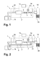
- a delivery unit 1 is shown, with which a liquid additive (in particular a urea-water solution) from a tank 19 can be transported to an injection device 8, wherein the injection device 8, the liquid additive in an exhaust gas treatment device 18 supplies.
- liquid urea-water solution is mixed with the exhaust gas flowing in the exhaust gas treatment device 18 and fed to an SCR catalytic converter 38.
- SCR process for the reduction of nitrogen oxide compounds in the exhaust gas can be carried out, the person skilled in the art being aware of the configuration of such SCR catalysts (eg honeycomb bodies with corresponding catalytic coating).
- the conveyor unit according to Fig. 1 has a pump 2, which is located in a delivery line 4, which extends from the tank 19 to the injection device 8 back.
- the delivery line 4 can be subdivided into a suction line section 35 extending from the tank 19 to the pump and into a pressure line section 34 extending from the pump 2 to the injection device 8.
- a pressure sensor 20 is connected, with which the pressure in the delivery line 4 (in the pressure line section 34) can be determined and / or monitored.
- the pressure sensor 20 and the pump 2 are connected to a control unit 15. With the control unit 15, the described method can be performed.
- the Fig. 1 is further indicated that in the delivery line 4 and air 7 (shown here in the manner of bubbles) is present. This air 7 can be conveyed out with the described method with the delivery line 4.
- the delivery line 4 can also be subdivided in a suction inlet section 35 from the tank 19 to the pump 2 and into a pressure line section 34 from the pump 2 to the injection device 8.
- a pressure line section 34 from the pump 2 to the injection device 8.
- a pressure sensor 20 connected, with which the pressure in the delivery line 4 (in the pressure line section 34) can be determined / monitored.
- the pressure sensor 20 and the pump 2 are also according to Fig. 2 connected to a control unit 15 with which the described method can be performed.
- Fig. 3 shows a sketch of a pump 2, which is suitable for a conveyor unit, with which the described method can be performed.
- the pump 2 is a metering pump, with which a precise metering of the liquid additive can take place (and the metering is not predetermined by a timed opening signal of an injector).
- the pump 2 has a movable pump element 3 which is reciprocable in a pump chamber to change the volume of the pump chamber 23. By a movement of the movable pump element 3, the volume of the pump chamber between a minimum pump chamber volume 37 and a maximum pump chamber volume 36 can be changed.
- Adjacent to the pump chamber 23 are two pump valves 24, via which liquid additive can be sucked into the pump chamber 23 during a suction phase of the pump 2 and pushed out of the pump chamber 23 during a delivery phase of the pump 2.
- the movable pump element 3 is movable between the minimum pump chamber volume 37 and the maximum pump chamber volume 36 in a movement range 6. Any pump element position 10 in the movement region 6 can be detected with the aid of a measuring device 22.
- the measuring means 22 is arranged on a rotary drive 13 of the pump 2.
- the rotary drive 13 is via a translation means 14, which according to Fig. 3 designed as a connecting rod, connected to the movable Punpenelement 3.
- the angular position 31 is representative of the pump element position 10 due to this fixed connection.
- Fig. 4 10 shows an automotive vehicle 16 (eg, a passenger car, a boat, a land vehicle, or a truck) comprising an internal combustion engine 17 (eg, a diesel engine) and an exhaust treatment device 18 adapted to purify the exhaust gases of the internal combustion engine 17.
- an injection device 8 the exhaust gas treatment device 18, a liquid additive can be supplied.
- an exhaust gas purification process for example, the selective catalytic reduction process, may be performed.
- the injection device 8 is supplied by a conveyor unit 1 with liquid additive.
- a control unit 15 is connected, with which the method described can be performed.
- Fig. 5 a diagram is shown, which should illustrate the operation of the conveyor unit.
- Fig. 5 shows 3 different curves with each other, each of which is plotted on a uniform time axis 25.
- the lowest curve is a pump element position curve 27, which shows the position of the pump element over time.
- suction phases 29 and delivery phases 28 of the delivery unit can be seen in the diagram. It can be seen that the moving pump element moves faster during suction phases 29 than during delivery phases 28 (the larger the curve in terms of magnitude).
- a suction phase 29 and a delivery phase 28 together correspond to a complete up and down movement of the movable pump element over the entire range of motion, as in Fig. 3 is shown.
- a (single) suction phase 29 and a (single) conveying phase 28 preferably correspond to a (single) rotation of the rotary drive through 360 °.
- a limit position 32 of the movable ramp element is marked on the vertical axis, which must be observed for step d) of the described method.
- a plurality of metering requirements 33 are preferably met, which are transmitted, for example, from a control unit to the conveyor unit.
- the middle curve in Fig. 5 is a pressure curve 26, which represents the pressure in the delivery line and in particular in a pressure line section of the delivery line. It can be seen that during the delivery phases 28 there is mostly a (approximately) constant delivery pressure 12 in the delivery line.
- the delivery pressure 12 preferably corresponds to the maximum pressure which exists in the delivery line and which is predetermined, for example, by an opening pressure of a (passive, spring-biased) valve on the injection device.
- the pressure in the delivery line drops to a minimum pressure 30. This is due to the fact that during the suction phase no liquid additive is conveyed into the delivery line, by which the pressure after / at the opening of the valve is maintained.
- the pressure in the delivery line in the delivery phase 28 is first established. This happens the slower the more air is in the delivery line. Therefore, at a time 5, the method step b) is carried out, in which it is determined that the pressure in the delivery line reaches a predetermined test pressure 11. It is monitored which pump element position 10 is present when the Test pressure 11 is reached at time 5. This pump element position 10 can then be used to perform the method step d) and determine whether the pump element position 10 exceeds the predetermined limit position 32. If this is the case, it is assumed that there is air in the delivery line.
- Fig. 6 is shown once again how the pressure curve 26 changes when air is present in the delivery line.
- the pressure curve 26 is also according to Fig. 6 Plotted on the time axis 25 and alternates between a minimum pressure 30 during suction phase and a delivery pressure 12 during delivery phases 28 back and forth.
- the pressure curve 26 shifts as in the upper region of the Fig. 6 indicated by dashed lines.
- the time 5 at which a test pressure 11 is reached in the delivery line shifts so backwards.
- the pump element position curve 27 is shown on the time axis 25.
- the different times 5 correspond respectively to different pump element positions 10.
- the limit position 32 is entered. If the pump element position 10 exceeds the limit position 32, air in the delivery line is detected in step d) of the method described.
- the method described makes it possible to detect air in the delivery line of a delivery unit for a liquid additive particularly reliably, without having to interrupt the delivery of the liquid additive to the delivery unit.
- the invention succeeds in solving or at least alleviating the technical problems described in connection with the prior art. It has been disclosed a particularly advantageous method for venting a liquid additive delivery unit, wherein the sensitivity of the monitoring and the dosing accuracy can be improved in the long term and simultaneously a retrofittable system was provided with little effort.
Landscapes
- Engineering & Computer Science (AREA)
- Chemical & Material Sciences (AREA)
- Chemical Kinetics & Catalysis (AREA)
- Combustion & Propulsion (AREA)
- Mechanical Engineering (AREA)
- General Engineering & Computer Science (AREA)
- Health & Medical Sciences (AREA)
- Toxicology (AREA)
- Exhaust Gas After Treatment (AREA)
Priority Applications (1)
| Application Number | Priority Date | Filing Date | Title |
|---|---|---|---|
| EP12290150.7A EP2660436B1 (fr) | 2012-05-03 | 2012-05-03 | Procédé de purge d'air d'une unité d'alimentation d'un additif liquide |
Applications Claiming Priority (1)
| Application Number | Priority Date | Filing Date | Title |
|---|---|---|---|
| EP12290150.7A EP2660436B1 (fr) | 2012-05-03 | 2012-05-03 | Procédé de purge d'air d'une unité d'alimentation d'un additif liquide |
Publications (2)
| Publication Number | Publication Date |
|---|---|
| EP2660436A1 true EP2660436A1 (fr) | 2013-11-06 |
| EP2660436B1 EP2660436B1 (fr) | 2016-06-15 |
Family
ID=46125343
Family Applications (1)
| Application Number | Title | Priority Date | Filing Date |
|---|---|---|---|
| EP12290150.7A Active EP2660436B1 (fr) | 2012-05-03 | 2012-05-03 | Procédé de purge d'air d'une unité d'alimentation d'un additif liquide |
Country Status (1)
| Country | Link |
|---|---|
| EP (1) | EP2660436B1 (fr) |
Cited By (4)
| Publication number | Priority date | Publication date | Assignee | Title |
|---|---|---|---|---|
| EP2955351A1 (fr) * | 2014-06-12 | 2015-12-16 | Toyota Jidosha Kabushiki Kaisha | Remplir d'un système d'alimentation eau-urée |
| US9512769B2 (en) | 2014-06-12 | 2016-12-06 | Toyota Jidosha Kabushiki Kaisha | Urea water supply system |
| JP2016205363A (ja) * | 2014-06-12 | 2016-12-08 | トヨタ自動車株式会社 | 尿素水供給システム |
| CN112648058A (zh) * | 2021-01-04 | 2021-04-13 | 东风汽车股份有限公司 | 一种发动机scr系统尿素喷射装置及其故障诊断方法 |
Citations (2)
| Publication number | Priority date | Publication date | Assignee | Title |
|---|---|---|---|---|
| EP1222370B1 (fr) | 1999-10-01 | 2003-12-03 | Robert Bosch Gmbh | Dispositif et procede pour doser un agent de reduction |
| DE102009056181A1 (de) * | 2009-11-27 | 2011-06-01 | Emitec Gesellschaft Für Emissionstechnologie Mbh | Verfahren zum Betrieb einer Fördervorrichtung für ein Reduktionsmittel |
-
2012
- 2012-05-03 EP EP12290150.7A patent/EP2660436B1/fr active Active
Patent Citations (2)
| Publication number | Priority date | Publication date | Assignee | Title |
|---|---|---|---|---|
| EP1222370B1 (fr) | 1999-10-01 | 2003-12-03 | Robert Bosch Gmbh | Dispositif et procede pour doser un agent de reduction |
| DE102009056181A1 (de) * | 2009-11-27 | 2011-06-01 | Emitec Gesellschaft Für Emissionstechnologie Mbh | Verfahren zum Betrieb einer Fördervorrichtung für ein Reduktionsmittel |
Cited By (6)
| Publication number | Priority date | Publication date | Assignee | Title |
|---|---|---|---|---|
| EP2955351A1 (fr) * | 2014-06-12 | 2015-12-16 | Toyota Jidosha Kabushiki Kaisha | Remplir d'un système d'alimentation eau-urée |
| US9512769B2 (en) | 2014-06-12 | 2016-12-06 | Toyota Jidosha Kabushiki Kaisha | Urea water supply system |
| JP2016205363A (ja) * | 2014-06-12 | 2016-12-08 | トヨタ自動車株式会社 | 尿素水供給システム |
| US9551261B2 (en) | 2014-06-12 | 2017-01-24 | Toyota Jidosha Kabushiki Kaisha | Urea water supply system |
| CN112648058A (zh) * | 2021-01-04 | 2021-04-13 | 东风汽车股份有限公司 | 一种发动机scr系统尿素喷射装置及其故障诊断方法 |
| CN112648058B (zh) * | 2021-01-04 | 2022-02-18 | 东风汽车股份有限公司 | 一种发动机scr系统尿素喷射装置及其故障诊断方法 |
Also Published As
| Publication number | Publication date |
|---|---|
| EP2660436B1 (fr) | 2016-06-15 |
Similar Documents
| Publication | Publication Date | Title |
|---|---|---|
| EP2898197B1 (fr) | Procédé de fonctionnement d'un dispositif de dosage | |
| EP2504540B1 (fr) | Procédé de fonctionement d'un dispositif d'alimentation d'un moyen de reduction | |
| EP2989305B1 (fr) | Procédé permettant de faire fonctionner un dispositif destiné à la délivrance dosée d'un liquide | |
| DE102012209538B4 (de) | Verfahren und Vorrichtung zum Überprüfen der Funktionstüchtigkeit von Hydraulikkomponenten in einem Abgasnachbehandlungssystem für ein Kraftfahrzeug | |
| DE102009023325B4 (de) | Verfahren zur Adaption der Injektionsmittelzufuhr in einem Injektionssystem | |
| DE102007044610B4 (de) | Verfahren zur Detektion der minimalen Öffnungszeit einer Reduktionsmittelzuführeinrichtung in einem Abgasnachbehandlungssystem mit einem SCR-Katalysator | |
| DE102014107903B4 (de) | Technik zur Bestimmung des Einspritzverhaltens eines Kraftstoffinjektors | |
| WO2014195082A1 (fr) | Procédé permettant de faire fonctionner un dispositif destiné à refouler un liquide | |
| WO2007124791A1 (fr) | Procédé et dispositif de dosage d'un agent de réduction dans un système d'échappement d'un moteur à combustion interne | |
| EP2660436B1 (fr) | Procédé de purge d'air d'une unité d'alimentation d'un additif liquide | |
| EP3469195B1 (fr) | Procédé de vidage d'un système de refoulement d'agent réducteur d'un catalyseur scr | |
| DE102007030555A1 (de) | Einspritzpumpenanordnung und Verfahren zum Einspritzen eines Fluids | |
| DE102017204300A1 (de) | Verfahren zur Diagnose eines SCR-Systems | |
| WO2012052357A1 (fr) | Procédé pour faire fonctionner un dispositif de dosage | |
| DE102013218552A1 (de) | Verfahren zum Betreiben eines hydraulischen Förder- und Dosiersystems | |
| EP2809898A2 (fr) | Procédé permettant de faire fonctionner un dispositif de dosage | |
| WO2012150103A1 (fr) | Dispositif de pompage pour système de dosage | |
| DE102010030858A1 (de) | Verfahren zur Überwachung einer Dosiereinrichtung | |
| DE102013104250A1 (de) | Verfahren zum Betrieb einer Vorrichtung zur dosierten Bereitstellung einer Flüssigkeit | |
| DE102013104242A1 (de) | Vorrichtung zur dosierten Bereitstellung einer Flüssigkeit | |
| DE102017209406B4 (de) | Verfahren und Vorrichtung zum Erkennen von defekten Komponenten eines Abgasnachbehandlungssystems | |
| DE102016210619A1 (de) | Verfahren zur Diagnose eines Reagenzmittel-Dosiersystems, Vorrichtung zur Durchführung des Verfahrens, Computer-Programm sowie Computer-Programmprodukt | |
| DE102016203841A1 (de) | Verfahren zum Betreiben eines Förder- und Dosiersystems für die Reduktionsmittellösung eines SCR-Katalysators | |
| EP4256182B1 (fr) | Procédé et dispositif permettant le dosage d'une solution d'urée aqueuse | |
| DE102019219636A1 (de) | Verfahren zum Betreiben eines Fluid-Versorgungssystem und Fluid-Versorgungssystem |
Legal Events
| Date | Code | Title | Description |
|---|---|---|---|
| PUAI | Public reference made under article 153(3) epc to a published international application that has entered the european phase |
Free format text: ORIGINAL CODE: 0009012 |
|
| AK | Designated contracting states |
Kind code of ref document: A1 Designated state(s): AL AT BE BG CH CY CZ DE DK EE ES FI FR GB GR HR HU IE IS IT LI LT LU LV MC MK MT NL NO PL PT RO RS SE SI SK SM TR |
|
| AX | Request for extension of the european patent |
Extension state: BA ME |
|
| 17P | Request for examination filed |
Effective date: 20131028 |
|
| RBV | Designated contracting states (corrected) |
Designated state(s): AL AT BE BG CH CY CZ DE DK EE ES FI FR GB GR HR HU IE IS IT LI LT LU LV MC MK MT NL NO PL PT RO RS SE SI SK SM TR |
|
| RAP1 | Party data changed (applicant data changed or rights of an application transferred) |
Owner name: EMITEC GESELLSCHAFT FUER EMISSIONSTECHNOLOGIE MBH |
|
| 17Q | First examination report despatched |
Effective date: 20150526 |
|
| GRAP | Despatch of communication of intention to grant a patent |
Free format text: ORIGINAL CODE: EPIDOSNIGR1 |
|
| INTG | Intention to grant announced |
Effective date: 20151207 |
|
| RIN1 | Information on inventor provided before grant (corrected) |
Inventor name: TRUONG, ANTHONY Inventor name: JANIAUT, MICHAEL Inventor name: KORNATZ, YAN |
|
| RAP1 | Party data changed (applicant data changed or rights of an application transferred) |
Owner name: CONTINENTAL AUTOMOTIVE GMBH |
|
| GRAS | Grant fee paid |
Free format text: ORIGINAL CODE: EPIDOSNIGR3 |
|
| GRAA | (expected) grant |
Free format text: ORIGINAL CODE: 0009210 |
|
| AK | Designated contracting states |
Kind code of ref document: B1 Designated state(s): AL AT BE BG CH CY CZ DE DK EE ES FI FR GB GR HR HU IE IS IT LI LT LU LV MC MK MT NL NO PL PT RO RS SE SI SK SM TR |
|
| REG | Reference to a national code |
Ref country code: CH Ref legal event code: EP Ref country code: GB Ref legal event code: FG4D Free format text: NOT ENGLISH |
|
| REG | Reference to a national code |
Ref country code: IE Ref legal event code: FG4D Free format text: LANGUAGE OF EP DOCUMENT: GERMAN |
|
| REG | Reference to a national code |
Ref country code: AT Ref legal event code: REF Ref document number: 806629 Country of ref document: AT Kind code of ref document: T Effective date: 20160715 |
|
| REG | Reference to a national code |
Ref country code: DE Ref legal event code: R096 Ref document number: 502012007405 Country of ref document: DE |
|
| REG | Reference to a national code |
Ref country code: LT Ref legal event code: MG4D |
|
| REG | Reference to a national code |
Ref country code: NL Ref legal event code: MP Effective date: 20160615 |
|
| PG25 | Lapsed in a contracting state [announced via postgrant information from national office to epo] |
Ref country code: LT Free format text: LAPSE BECAUSE OF FAILURE TO SUBMIT A TRANSLATION OF THE DESCRIPTION OR TO PAY THE FEE WITHIN THE PRESCRIBED TIME-LIMIT Effective date: 20160615 Ref country code: NO Free format text: LAPSE BECAUSE OF FAILURE TO SUBMIT A TRANSLATION OF THE DESCRIPTION OR TO PAY THE FEE WITHIN THE PRESCRIBED TIME-LIMIT Effective date: 20160915 Ref country code: FI Free format text: LAPSE BECAUSE OF FAILURE TO SUBMIT A TRANSLATION OF THE DESCRIPTION OR TO PAY THE FEE WITHIN THE PRESCRIBED TIME-LIMIT Effective date: 20160615 |
|
| PG25 | Lapsed in a contracting state [announced via postgrant information from national office to epo] |
Ref country code: HR Free format text: LAPSE BECAUSE OF FAILURE TO SUBMIT A TRANSLATION OF THE DESCRIPTION OR TO PAY THE FEE WITHIN THE PRESCRIBED TIME-LIMIT Effective date: 20160615 Ref country code: GR Free format text: LAPSE BECAUSE OF FAILURE TO SUBMIT A TRANSLATION OF THE DESCRIPTION OR TO PAY THE FEE WITHIN THE PRESCRIBED TIME-LIMIT Effective date: 20160916 Ref country code: SE Free format text: LAPSE BECAUSE OF FAILURE TO SUBMIT A TRANSLATION OF THE DESCRIPTION OR TO PAY THE FEE WITHIN THE PRESCRIBED TIME-LIMIT Effective date: 20160615 Ref country code: NL Free format text: LAPSE BECAUSE OF FAILURE TO SUBMIT A TRANSLATION OF THE DESCRIPTION OR TO PAY THE FEE WITHIN THE PRESCRIBED TIME-LIMIT Effective date: 20160615 Ref country code: RS Free format text: LAPSE BECAUSE OF FAILURE TO SUBMIT A TRANSLATION OF THE DESCRIPTION OR TO PAY THE FEE WITHIN THE PRESCRIBED TIME-LIMIT Effective date: 20160615 Ref country code: LV Free format text: LAPSE BECAUSE OF FAILURE TO SUBMIT A TRANSLATION OF THE DESCRIPTION OR TO PAY THE FEE WITHIN THE PRESCRIBED TIME-LIMIT Effective date: 20160615 |
|
| PG25 | Lapsed in a contracting state [announced via postgrant information from national office to epo] |
Ref country code: RO Free format text: LAPSE BECAUSE OF FAILURE TO SUBMIT A TRANSLATION OF THE DESCRIPTION OR TO PAY THE FEE WITHIN THE PRESCRIBED TIME-LIMIT Effective date: 20160615 Ref country code: IS Free format text: LAPSE BECAUSE OF FAILURE TO SUBMIT A TRANSLATION OF THE DESCRIPTION OR TO PAY THE FEE WITHIN THE PRESCRIBED TIME-LIMIT Effective date: 20161015 Ref country code: SK Free format text: LAPSE BECAUSE OF FAILURE TO SUBMIT A TRANSLATION OF THE DESCRIPTION OR TO PAY THE FEE WITHIN THE PRESCRIBED TIME-LIMIT Effective date: 20160615 Ref country code: CZ Free format text: LAPSE BECAUSE OF FAILURE TO SUBMIT A TRANSLATION OF THE DESCRIPTION OR TO PAY THE FEE WITHIN THE PRESCRIBED TIME-LIMIT Effective date: 20160615 Ref country code: IT Free format text: LAPSE BECAUSE OF FAILURE TO SUBMIT A TRANSLATION OF THE DESCRIPTION OR TO PAY THE FEE WITHIN THE PRESCRIBED TIME-LIMIT Effective date: 20160615 Ref country code: EE Free format text: LAPSE BECAUSE OF FAILURE TO SUBMIT A TRANSLATION OF THE DESCRIPTION OR TO PAY THE FEE WITHIN THE PRESCRIBED TIME-LIMIT Effective date: 20160615 |
|
| PG25 | Lapsed in a contracting state [announced via postgrant information from national office to epo] |
Ref country code: PL Free format text: LAPSE BECAUSE OF FAILURE TO SUBMIT A TRANSLATION OF THE DESCRIPTION OR TO PAY THE FEE WITHIN THE PRESCRIBED TIME-LIMIT Effective date: 20160615 Ref country code: PT Free format text: LAPSE BECAUSE OF FAILURE TO SUBMIT A TRANSLATION OF THE DESCRIPTION OR TO PAY THE FEE WITHIN THE PRESCRIBED TIME-LIMIT Effective date: 20161017 Ref country code: ES Free format text: LAPSE BECAUSE OF FAILURE TO SUBMIT A TRANSLATION OF THE DESCRIPTION OR TO PAY THE FEE WITHIN THE PRESCRIBED TIME-LIMIT Effective date: 20160615 Ref country code: SM Free format text: LAPSE BECAUSE OF FAILURE TO SUBMIT A TRANSLATION OF THE DESCRIPTION OR TO PAY THE FEE WITHIN THE PRESCRIBED TIME-LIMIT Effective date: 20160615 |
|
| REG | Reference to a national code |
Ref country code: DE Ref legal event code: R097 Ref document number: 502012007405 Country of ref document: DE |
|
| PLBE | No opposition filed within time limit |
Free format text: ORIGINAL CODE: 0009261 |
|
| STAA | Information on the status of an ep patent application or granted ep patent |
Free format text: STATUS: NO OPPOSITION FILED WITHIN TIME LIMIT |
|
| REG | Reference to a national code |
Ref country code: FR Ref legal event code: PLFP Year of fee payment: 6 |
|
| 26N | No opposition filed |
Effective date: 20170316 |
|
| PG25 | Lapsed in a contracting state [announced via postgrant information from national office to epo] |
Ref country code: DK Free format text: LAPSE BECAUSE OF FAILURE TO SUBMIT A TRANSLATION OF THE DESCRIPTION OR TO PAY THE FEE WITHIN THE PRESCRIBED TIME-LIMIT Effective date: 20160615 |
|
| PG25 | Lapsed in a contracting state [announced via postgrant information from national office to epo] |
Ref country code: SI Free format text: LAPSE BECAUSE OF FAILURE TO SUBMIT A TRANSLATION OF THE DESCRIPTION OR TO PAY THE FEE WITHIN THE PRESCRIBED TIME-LIMIT Effective date: 20160615 Ref country code: LU Free format text: LAPSE BECAUSE OF NON-PAYMENT OF DUE FEES Effective date: 20170531 |
|
| REG | Reference to a national code |
Ref country code: CH Ref legal event code: PL |
|
| GBPC | Gb: european patent ceased through non-payment of renewal fee |
Effective date: 20170503 |
|
| PG25 | Lapsed in a contracting state [announced via postgrant information from national office to epo] |
Ref country code: MC Free format text: LAPSE BECAUSE OF FAILURE TO SUBMIT A TRANSLATION OF THE DESCRIPTION OR TO PAY THE FEE WITHIN THE PRESCRIBED TIME-LIMIT Effective date: 20160615 |
|
| REG | Reference to a national code |
Ref country code: IE Ref legal event code: MM4A |
|
| PG25 | Lapsed in a contracting state [announced via postgrant information from national office to epo] |
Ref country code: CH Free format text: LAPSE BECAUSE OF NON-PAYMENT OF DUE FEES Effective date: 20170531 Ref country code: LI Free format text: LAPSE BECAUSE OF NON-PAYMENT OF DUE FEES Effective date: 20170531 |
|
| PG25 | Lapsed in a contracting state [announced via postgrant information from national office to epo] |
Ref country code: LU Free format text: LAPSE BECAUSE OF NON-PAYMENT OF DUE FEES Effective date: 20170503 |
|
| REG | Reference to a national code |
Ref country code: BE Ref legal event code: MM Effective date: 20170531 |
|
| PG25 | Lapsed in a contracting state [announced via postgrant information from national office to epo] |
Ref country code: IE Free format text: LAPSE BECAUSE OF NON-PAYMENT OF DUE FEES Effective date: 20170503 Ref country code: GB Free format text: LAPSE BECAUSE OF NON-PAYMENT OF DUE FEES Effective date: 20170503 |
|
| REG | Reference to a national code |
Ref country code: FR Ref legal event code: PLFP Year of fee payment: 7 |
|
| REG | Reference to a national code |
Ref country code: AT Ref legal event code: MM01 Ref document number: 806629 Country of ref document: AT Kind code of ref document: T Effective date: 20170503 |
|
| PG25 | Lapsed in a contracting state [announced via postgrant information from national office to epo] |
Ref country code: BE Free format text: LAPSE BECAUSE OF NON-PAYMENT OF DUE FEES Effective date: 20170531 Ref country code: AT Free format text: LAPSE BECAUSE OF NON-PAYMENT OF DUE FEES Effective date: 20170503 |
|
| PG25 | Lapsed in a contracting state [announced via postgrant information from national office to epo] |
Ref country code: MT Free format text: LAPSE BECAUSE OF FAILURE TO SUBMIT A TRANSLATION OF THE DESCRIPTION OR TO PAY THE FEE WITHIN THE PRESCRIBED TIME-LIMIT Effective date: 20160615 |
|
| PG25 | Lapsed in a contracting state [announced via postgrant information from national office to epo] |
Ref country code: AL Free format text: LAPSE BECAUSE OF FAILURE TO SUBMIT A TRANSLATION OF THE DESCRIPTION OR TO PAY THE FEE WITHIN THE PRESCRIBED TIME-LIMIT Effective date: 20160615 |
|
| PG25 | Lapsed in a contracting state [announced via postgrant information from national office to epo] |
Ref country code: HU Free format text: LAPSE BECAUSE OF FAILURE TO SUBMIT A TRANSLATION OF THE DESCRIPTION OR TO PAY THE FEE WITHIN THE PRESCRIBED TIME-LIMIT; INVALID AB INITIO Effective date: 20120503 |
|
| PG25 | Lapsed in a contracting state [announced via postgrant information from national office to epo] |
Ref country code: BG Free format text: LAPSE BECAUSE OF FAILURE TO SUBMIT A TRANSLATION OF THE DESCRIPTION OR TO PAY THE FEE WITHIN THE PRESCRIBED TIME-LIMIT Effective date: 20160615 |
|
| PG25 | Lapsed in a contracting state [announced via postgrant information from national office to epo] |
Ref country code: CY Free format text: LAPSE BECAUSE OF NON-PAYMENT OF DUE FEES Effective date: 20160615 |
|
| PG25 | Lapsed in a contracting state [announced via postgrant information from national office to epo] |
Ref country code: MK Free format text: LAPSE BECAUSE OF FAILURE TO SUBMIT A TRANSLATION OF THE DESCRIPTION OR TO PAY THE FEE WITHIN THE PRESCRIBED TIME-LIMIT Effective date: 20160615 |
|
| PG25 | Lapsed in a contracting state [announced via postgrant information from national office to epo] |
Ref country code: TR Free format text: LAPSE BECAUSE OF FAILURE TO SUBMIT A TRANSLATION OF THE DESCRIPTION OR TO PAY THE FEE WITHIN THE PRESCRIBED TIME-LIMIT Effective date: 20160615 |
|
| REG | Reference to a national code |
Ref country code: DE Ref legal event code: R081 Ref document number: 502012007405 Country of ref document: DE Owner name: VITESCO TECHNOLOGIES GMBH, DE Free format text: FORMER OWNER: CONTINENTAL AUTOMOTIVE GMBH, 30165 HANNOVER, DE |
|
| REG | Reference to a national code |
Ref country code: DE Ref legal event code: R084 Ref document number: 502012007405 Country of ref document: DE |
|
| REG | Reference to a national code |
Ref country code: DE Ref legal event code: R081 Ref document number: 502012007405 Country of ref document: DE Owner name: VITESCO TECHNOLOGIES GMBH, DE Free format text: FORMER OWNER: VITESCO TECHNOLOGIES GMBH, 30165 HANNOVER, DE |
|
| P01 | Opt-out of the competence of the unified patent court (upc) registered |
Effective date: 20230530 |
|
| PGFP | Annual fee paid to national office [announced via postgrant information from national office to epo] |
Ref country code: DE Payment date: 20240531 Year of fee payment: 13 |
|
| PGFP | Annual fee paid to national office [announced via postgrant information from national office to epo] |
Ref country code: FR Payment date: 20240528 Year of fee payment: 13 |