EP1221694A1 - Codeur/decodeur vocal - Google Patents
Codeur/decodeur vocal Download PDFInfo
- Publication number
- EP1221694A1 EP1221694A1 EP99943314A EP99943314A EP1221694A1 EP 1221694 A1 EP1221694 A1 EP 1221694A1 EP 99943314 A EP99943314 A EP 99943314A EP 99943314 A EP99943314 A EP 99943314A EP 1221694 A1 EP1221694 A1 EP 1221694A1
- Authority
- EP
- European Patent Office
- Prior art keywords
- signal
- algebraic codebook
- pitch lag
- pulse
- frame
- Prior art date
- Legal status (The legal status is an assumption and is not a legal conclusion. Google has not performed a legal analysis and makes no representation as to the accuracy of the status listed.)
- Granted
Links
- 230000003044 adaptive effect Effects 0.000 claims abstract description 89
- 238000003786 synthesis reaction Methods 0.000 claims abstract description 46
- 230000015572 biosynthetic process Effects 0.000 claims abstract description 45
- 238000000034 method Methods 0.000 claims abstract description 33
- 238000005070 sampling Methods 0.000 claims description 70
- 230000003111 delayed effect Effects 0.000 claims description 6
- 230000000694 effects Effects 0.000 claims description 5
- 238000013139 quantization Methods 0.000 description 49
- 239000013598 vector Substances 0.000 description 33
- 238000012545 processing Methods 0.000 description 28
- 238000010586 diagram Methods 0.000 description 24
- 238000011156 evaluation Methods 0.000 description 12
- 230000004044 response Effects 0.000 description 5
- 238000012546 transfer Methods 0.000 description 4
- 238000005311 autocorrelation function Methods 0.000 description 3
- 238000004891 communication Methods 0.000 description 3
- 230000001755 vocal effect Effects 0.000 description 3
- 230000005540 biological transmission Effects 0.000 description 2
- 239000000872 buffer Substances 0.000 description 2
- 230000008859 change Effects 0.000 description 2
- 230000006835 compression Effects 0.000 description 2
- 238000007906 compression Methods 0.000 description 2
- 230000003247 decreasing effect Effects 0.000 description 2
- 230000006866 deterioration Effects 0.000 description 2
- 238000010295 mobile communication Methods 0.000 description 2
- 230000001052 transient effect Effects 0.000 description 2
- 240000001973 Ficus microcarpa Species 0.000 description 1
- 238000004364 calculation method Methods 0.000 description 1
- 238000010276 construction Methods 0.000 description 1
- 230000005284 excitation Effects 0.000 description 1
- 238000002474 experimental method Methods 0.000 description 1
- 239000000284 extract Substances 0.000 description 1
- 230000008569 process Effects 0.000 description 1
- 230000009467 reduction Effects 0.000 description 1
- 238000009877 rendering Methods 0.000 description 1
- 230000000717 retained effect Effects 0.000 description 1
- 238000001228 spectrum Methods 0.000 description 1
- 230000017105 transposition Effects 0.000 description 1
Images


Classifications
-
- G—PHYSICS
- G10—MUSICAL INSTRUMENTS; ACOUSTICS
- G10L—SPEECH ANALYSIS TECHNIQUES OR SPEECH SYNTHESIS; SPEECH RECOGNITION; SPEECH OR VOICE PROCESSING TECHNIQUES; SPEECH OR AUDIO CODING OR DECODING
- G10L19/00—Speech or audio signals analysis-synthesis techniques for redundancy reduction, e.g. in vocoders; Coding or decoding of speech or audio signals, using source filter models or psychoacoustic analysis
- G10L19/04—Speech or audio signals analysis-synthesis techniques for redundancy reduction, e.g. in vocoders; Coding or decoding of speech or audio signals, using source filter models or psychoacoustic analysis using predictive techniques
- G10L19/08—Determination or coding of the excitation function; Determination or coding of the long-term prediction parameters
- G10L19/09—Long term prediction, i.e. removing periodical redundancies, e.g. by using adaptive codebook or pitch predictor
-
- G—PHYSICS
- G10—MUSICAL INSTRUMENTS; ACOUSTICS
- G10L—SPEECH ANALYSIS TECHNIQUES OR SPEECH SYNTHESIS; SPEECH RECOGNITION; SPEECH OR VOICE PROCESSING TECHNIQUES; SPEECH OR AUDIO CODING OR DECODING
- G10L19/00—Speech or audio signals analysis-synthesis techniques for redundancy reduction, e.g. in vocoders; Coding or decoding of speech or audio signals, using source filter models or psychoacoustic analysis
- G10L19/04—Speech or audio signals analysis-synthesis techniques for redundancy reduction, e.g. in vocoders; Coding or decoding of speech or audio signals, using source filter models or psychoacoustic analysis using predictive techniques
- G10L19/08—Determination or coding of the excitation function; Determination or coding of the long-term prediction parameters
- G10L19/10—Determination or coding of the excitation function; Determination or coding of the long-term prediction parameters the excitation function being a multipulse excitation
- G10L19/107—Sparse pulse excitation, e.g. by using algebraic codebook
-
- G—PHYSICS
- G10—MUSICAL INSTRUMENTS; ACOUSTICS
- G10L—SPEECH ANALYSIS TECHNIQUES OR SPEECH SYNTHESIS; SPEECH RECOGNITION; SPEECH OR VOICE PROCESSING TECHNIQUES; SPEECH OR AUDIO CODING OR DECODING
- G10L19/00—Speech or audio signals analysis-synthesis techniques for redundancy reduction, e.g. in vocoders; Coding or decoding of speech or audio signals, using source filter models or psychoacoustic analysis
- G10L19/04—Speech or audio signals analysis-synthesis techniques for redundancy reduction, e.g. in vocoders; Coding or decoding of speech or audio signals, using source filter models or psychoacoustic analysis using predictive techniques
- G10L19/16—Vocoder architecture
- G10L19/18—Vocoders using multiple modes
-
- G—PHYSICS
- G10—MUSICAL INSTRUMENTS; ACOUSTICS
- G10L—SPEECH ANALYSIS TECHNIQUES OR SPEECH SYNTHESIS; SPEECH RECOGNITION; SPEECH OR VOICE PROCESSING TECHNIQUES; SPEECH OR AUDIO CODING OR DECODING
- G10L19/00—Speech or audio signals analysis-synthesis techniques for redundancy reduction, e.g. in vocoders; Coding or decoding of speech or audio signals, using source filter models or psychoacoustic analysis
- G10L2019/0001—Codebooks
- G10L2019/0007—Codebook element generation
- G10L2019/0008—Algebraic codebooks
Definitions
- This invention relates to a voice encoding and voice decoding apparatus for encoding/decoding voice at a low bit rate of below 4 kbps. More particularly, the invention relates to a voice encoding and voice decoding apparatus for encoding/decoding voice at low bit rates using an A-b-S (Analysis-by-Synthesis)-type vector quantization. It is expected that A-b-S voice encoding typified by CELP (Code Excited Linear Predictive Coding) will be an effective scheme for implementing highly efficient compression of information while maintaining speech quality in digital mobile communications and intercorporate communications systems.
- CELP Code Excited Linear Predictive Coding
- CELP Code Excited Linear Prediction
- Fig. 15 is a diagram illustrating the principles of CELP.
- the human vocal tract is approximated by an LPC synthesis filter H(z) expressed by the following equation: and it is assumed that the input (sound-source signal) to H(z) can be separated into (1) a pitch-period component representing the periodicity of speech and (2) a noise component representing randomness.
- CELP rather than transmitting the input voice signal to the decoder side directly, extracts the filter coefficients of the LPC synthesis filter and the pitch-period component and noise component of the excitation signal, quantizes these to obtain quantization indices and transmits the quantization indices, thereby implementing a high degree of information compression.
- Fig. 16 is a diagram useful in describing the quantization method. Here sets of large numbers of quantization LPC coefficients have been stored in a quantization table 2a in correspondence with index numbers 1 to n.
- a minimum-distance index detector 2c finds the q for which the distance d is minimum and sends the index q to the decoder side.
- an LPC synthesis filter constituting an auditory weighting synthesis filter 3 is expressed by the following equation:
- a sound-source signal is divided into two components, namely a pitch-period component and a noise component, an adaptive codebook 4 storing a sequence of past sound-source signals is used to quantize the pitch-period component and an algebraic codebook or noise codebook is used to quantize the noise component.
- an adaptive codebook 4 storing a sequence of past sound-source signals is used to quantize the pitch-period component
- an algebraic codebook or noise codebook is used to quantize the noise component. Described below will be typical CELP-type voice encoding using the adaptive codebook 4 and algebraic codebook 5 as sound-source codebooks.
- the adaptive codebook 4 is adapted to successively output N samples of sound-source signals (referred to as "periodicity signals"), which are delayed by one pitch (one sample), in association with indices 1 to L.
- the adaptive codebook is constituted by a buffer BF for storing the pitch-period component of the latest 227 samples.
- a periodicity signal comprising 1 to 80 samples is specified by index 1
- a periodicity signal comprising 2 to 81 samples is specified by index 2
- ⁇ a periodicity signal comprising 147 to 227 samples
- An adaptive-codebook search is performed in accordance with the following procedure: First, a bit lag L representing lag from the present frame is set to an initial value L 0 (e.g., 20). Next, a past periodicity signal (adaptive code vector) P L , which corresponds to the lag L, is extracted from the adaptive codebook 4. That is, an adaptive code vector P L indicated by index L is extracted and P L is input to the auditory weighting synthesis filter 3 to obtain an output AP L , where A represents the impulse response of the auditory weighting synthesis filter 3 constructed by cascade connecting an auditory weighting filter W(z) and an LPC synthesis filter Hq(z).
- any filter can be used as the auditory weighting filter.
- an adaptive code vector P L at a pitch lag Lopt for which the error power of Equation (4) is minimum will be expressed by the following equation: where T signifies a transposition. Accordingly, an error-power evaluation unit 7 finds the pitch lag Lopt that satisfies Equation (5).
- the algebraic codebook 5 is constituted by a plurality of pulses of amplitude 1 or -1.
- Fig. 18 illustrates pulse positions for a case where frame length is 40 samples.
- Fig. 19 is a diagram useful in describing sampling points assigned to each of the pulse-system groups 1 to 4.
- the algebraic codebook search will now be described with regard to this example.
- the pulse positions of each of the pulse systems group are limited as illustrated in Fig. 18.
- a combination of pulses for which the error power relative to the input voice is minimized in the reconstruction region is decided from among the combinations of pulse positions of each of the pulse systems. More specifically, with ⁇ opt as the optimum pitch gain found by the adaptive codebook search, the output PL of the adaptive codebook is multiplied by the gain ⁇ opt and the product is input to an adder 8.
- the pulsed signals are input successively to the adder 8 from the algebraic codebook 5 and a pulsed signal is specified that will minimize the difference between the input signal X and a reconstructed signal obtained by inputting the adder output to the weighting synthesis filter 3.
- a target vector X' for an algebraic codebook search is generated in accordance with the following equation from the optimum adaptive codebook output P L and optimum pitch gain ⁇ opt obtained from the input signal X by the adaptive codebook search:
- X' X - ⁇ optAP L
- pulse position and amplitude (sign) are expressed by 17 bits and therefore 2 17 combinations exist, as mentioned above.
- C K represent a kth algebraic-code output vector
- the error-power evaluation unit 7 searches for k as set forth below.
- Equation (1) Q k in the numerator of Equation (1) is represented by the following equation: where S k (i) is the pulse amplitude (+1 or -1) in the ith pulse system of C k and m k (i) represents the position of the pulse. Further, the denominator E k of Equation (10) is found by the following equation: It is also possible to conduct a search using Q k in Equation (13) and E k in Equation (14).
- the gain quantization method is optional and a method such as scalar quantization or vector quantization can be used. For example, it is so arranged that ⁇ , ⁇ are quantized and the quantization indices of the gain are transmitted to the decoder through a method similar to that employed by the LPC-coefficient quantizer 2.
- an output information selector 9 sends the decoder (1) the quantization index of the LPC coefficient, (2) pitch lag Lopt, (3) an algebraic codebook index (pulsed-signal specifying data), and (4) a quantization index of gain.
- the state of the adaptive codebook 4 is updated.
- state updating a frame length of the sound-source signal of the oldest frame (the frame farthest in the past) in the adaptive codebook is discarded and a frame length of the latest sound-source signal found in the present frame is stored.
- the initial state of the adaptive codebook 4 is the zero state, i.e., a state in which the amplitudes of all samples are zero.
- the CELP system produces a model of the speech generation process, quantizes the characteristic parameters of this model and transmits the parameters, thereby making it possible to compress speech efficiently.
- CELP (and improvements therein) makes it possible to realize high-quality reconstructed speech at a bit rate on the order of 8 to 16 kbps.
- ITU-T Recommendation G.729A (CS-ACELP) makes it possible to achieve a sound quality equal to that of 32-kbps ADPCM on the condition of a low bit rate of 8 kbps. From the standpoint of effective utilization of the communication channel, however, there is now a need to implement high-quality reconstructed speech at a very low bit rate of less than 4 kbps.
- the simplest method of reducing bit rate is to raise the efficiency of vector quantization by increasing frame length, which is the unit of encoding.
- the CS-ACELP frame length is 5 ms (40 samples) and, as mentioned above, the noise component of the sound-source signal is vector-quantized at 17 bits per frame.
- Fig. 20 illustrates an example of pulse placement in a case where four pulses reside in a 10-ms frame.
- the pulses (sampling points and polarities) of first to third pulse systems in Fig. 20 are each represented by five bits and the pulses of a fourth pulse system are represented by six bits, so that 21 bits are necessary to express the indices of the algebraic codebook. That is, in a case where the algebraic codebook is used, if frame length is simply doubled to 10 ms, the combinations of pulses increase by an amount commensurate with the increase in positions at which pulses reside unless the number of pulses per frame is reduced. As a consequence, the number of quantization bits also increases.
- the only method available to make the number of bits of the algebraic codebook indices equal to 17 is to reduce the number of pulses, as illustrated in Fig. 21 by way of example.
- the quality of reconstructed speech deteriorates markedly when the number of pulses per frame is made three or less. This phenomenon can be readily understood qualitatively. Specifically, if there are four pulses per frame (Fig. 18) in a case where the frame length is 5 ms, then eight pulses will be present in 10 ms. By contrast, if there are three pulses per frame (Fig.
- bit rate cannot be reduced unless the number of pulses per frame is reduced. If the number of pulses is reduced, however, the quality of reconstructed speech deteriorates by a wide margin. Accordingly, with the method of raising the efficiency of vector quantization simply by increasing frame length, achieving high-quality reconstructed speed at a bit rate of 4 kbps is difficult.
- an object of the present invention is to make it possible to reduce the bit rate and reconstruct high-quality speech.
- an encoder sends a decoder (1) a quantization index of an LPC coefficient, (2) pitch lag Lopt of an adaptive codebook, (3) an algebraic codebook index (pulsed-signal specifying data), and (4) a quantization index of gain.
- eight bits are necessary to transmit the pitch lag. If pitch lag need not be sent, therefore, the number of bits used to express the algebraic codebook index can be increased commensurately. In other words, the number of pulses contained in the pulsed signal output from the algebraic codebook can be increased and it therefore becomes possible to transmit high-quality voice code and to achieve high-quality reproduction.
- pitch lag need not be sent, therefore, the number of bits used to express the algebraic codebook index can be increased commensurately. In other words, the number of pulses contained in the pulsed signal output from the algebraic codebook can be increased and it therefore becomes possible to transmit high-quality voice code and to achieve high-quality reproduction.
- a steady segment of speech is such that the pitch period varies slowly. The quality of
- an encoding mode 1 that uses pitch lag obtained from an input signal of a present frame
- an encoding mode 2 that uses pitch lag obtained from an input signal of a past frame
- a first algebraic codebook having a small number of pulses is used in the encoding mode 1
- a second algebraic codebook having a large number of pulses is used in the encoding mode 2.
- an encoder carries out encoding frame by frame in each of the encoding modes 1 and 2 and sends a decoder a code obtained by encoding an input signal in whichever mode enables more accurate reconstruction of the input signal. If this arrangement is adopted, the bit rate can be reduced and it becomes possible to reconstruct high-quality speech.
- an encoding mode 1 that uses pitch lag obtained from an input signal of a present frame
- an encoding mode 2 that uses pitch lag obtained from an input signal of a past frame
- a first algebraic codebook having a small number of pulses is used in the encoding mode 1
- a second algebraic codebook in which the number of pulses is greater than that of the first algebraic codebook is used in the encoding mode 2.
- the optimum mode is decided based upon a property of the input signal, e.g., the periodicity of the input signal, and encoding is carried out on the basis of the mode decided. If this arrangement is adopted, the bit rate can be reduced and it becomes possible to reconstruct high-quality speech.
- the present invention provides a first encoding mode (mode 0), which uses pitch lag obtained from an input signal of a present frame, as pitch lag of a present frame and uses an algebraic codebook of a small number of pulses and a second encoding mode (mode 1) that uses pitch lag obtained from an input signal of a past frame, e.g., the immediately preceding frame, and uses an algebraic codebook, the number of pulses of which is greater than that of the algebraic codebook used in mode 0.
- the mode in which encoding is performed is decided depending upon which mode makes it possible to reconstruct speech faithfully. Since the number of pulses can be increased in mode 1, the noise component of a voice signal can be expressed more faithfully as compared with mode 0.
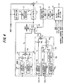
- Fig. 1 is a diagram useful in describing a first overview of the present invention.
- the number of dimensions of x is assumed to be the same as the number N of samples constituting a frame.
- the number of dimensions of a vector is assumed to be N unless specified otherwise.
- An LPC synthesis filter 13 representing the speech characteristics of the human vocal tract in constituted by ⁇ (i) and the transfer function thereof is represented by the following equation:
- a first encoder 14 that operates in mode 0 has an adaptive codebook (adaptive codebook 0) 14a, an algebraic codebook (algebraic codebook 0) 14b, gain multipliers 14c, 14d and an adder 14e.
- a second encoder 15 that operates in mode 1 has an adaptive codebook (adaptive codebook 1) 15a, an algebraic codebook (algebraic codebook 1) 15b, gain multipliers 15c, 15d and an adder 15e.
- the adaptive codebooks 14a, 15a are implemented by buffers that store the pitch-period components of the latest n samples in the past, as described in conjunction with Fig. 17.
- the placement of pulses of the algebraic codebook 14b in the first encoder 14 is as shown in Fig. 2.
- the placement of pulses of the algebraic codebook 15b in the second encoder 15 is as shown in Fig. 3.
- Five bits are required to express the pulse positions and pulse polarities in all of the pulse-system groups 0 to 4.
- the first encoder 14 has the same structure as that used in ordinary CELP, and the codebook search also is performed in the same manner as CELP. Specifically, pitch lag L is varied over a predetermined range (e.g., 20 to 147) in the first adaptive codebook 14a, adaptive codebook output P 0 (L) at each pitch lag is input to the LPC filter 13 via a mode changeover unit 16, an arithmetic unit 17 calculates error power between the LPC synthesis filter output signal and the input signal x, and an error-power evaluation unit 18 finds an optimum pitch lag Lag and an optimum pitch gain ⁇ 0 for which error power is minimized.
- a predetermined range e.g. 20 to 147
- P 0 (L) at each pitch lag is input to the LPC filter 13 via a mode changeover unit 16
- an arithmetic unit 17 calculates error power between the LPC synthesis filter output signal and the input signal x
- an error-power evaluation unit 18 finds an optimum pitch lag Lag and
- m 2 17 represents the size of the algebraic codebook 14b (the total number of combinations of pulses).
- Mode 1 differs from mode 0 in that the adaptive codebook search is not conducted. It is generally known that a steady segment of speech is such that the pitch period varies slowly. The quality of reconstructed speech will suffer almost no deterioration in the steady segment even if pitch lag of the present frame is regarded as being the same as pitch lag in a past (e.g., the immediately preceding) frame. In such case it is unnecessary to send pitch lag to a decoder and hence leeway equivalent to the number of bits (e.g., eight) necessary to encode pitch lag is produced.
- these eight bits are used to express the index of the algebraic codebook. If this expedient is adopted, the placement of pulses in the algebraic codebook 15b can be made as shown in Fig. 3 and the number of pulses of the pulse signal can be increased. When the number of transmitted bits of an algebraic codebook (or noise codebook, etc.) is enlarged in CELP, a more complicated sound-source signal can be expressed and the quality of reconstructed speech is improved.
- the second encoder 15 does not conduct an adaptive codebook search, regards optimum pitch lag lag_old, which was obtained in a past frame (e.g., the preceding frame), as optimum lag of the present frame and finds the optimum pitch gain ⁇ 1 prevailing at this time.
- the second encoder 15 conducts an algebraic codebook search using the algebraic codebook 15b in a manner similar to that of the algebraic codebook search in the first encoder 14, and decides an optimum index I 1 and optimum algebraic codebook gain ⁇ 1 specifying a pulsed signal for which the error power is smallest.
- the error-power evaluation unit 18 calculates each error power between the sound-source vectors e 0 , e 1 and input signal.
- a mode decision unit 19 compares the error power values that enter from the error-power evaluation unit 18 and decides the mode which will finally be used is that which provides the smaller error power.
- An output-information selector 20 selects, and transmits to the decoder, mode information, LPC quantization index, pitch lag and the algebraic codebook index and gain quantization index of the mode used.
- the state of the adaptive codebook is updated before the input signal of the next frame is processed.
- state updating a frame length of the sound-source signal of the oldest frame (the frame farthest in the past) in the adaptive codebook is discarded and the latest sound-source signal e x (sound-source signal e 0 or e 1 ) found in the present frame is stored.
- the initial state of the adaptive codebook is assumed to be the zero state.
- the mode finally used is decided after the adaptive codebook search / algebraic codebook search are conducted in all modes (modes 0, 1).
- the above description is rendered using two adaptive codebooks. However, since exactly the same past sound-source signals will have been stored in the two adaptive codebooks, implementation is permissible using one of the adaptive codebooks.
- Fig. 4 is a diagram useful in describing a second overview of the present invention, in which components identical with those shown in Fig. 1 are designated by like reference characters. This arrangement differs in the construction of the second encoder 15.
- the algebraic codebook 15b of the second encoder 15 Provided as the algebraic codebook 15b of the second encoder 15 are (1) a first algebraic codebook 15b 1 and (2) a second algebraic codebook 15b 2 in which the number of pulses is greater than that of the first algebraic codebook 15b 1 .
- the first algebraic codebook 15b 1 has the pulse placement shown in Fig. 3.
- an algebraic codebook changeover unit 15f selects the pulsed signal output of the first algebraic codebook 15b 1 if the value of Lag_old in the past is greater than M, and selects the pulsed signal output of the second algebraic codebook 15b 2 if the value of Lag_old is less than M.
- a pitch periodizing unit 15g executes pitch periodization processing for repeatedly outputting the pulsed signal pattern of the second algebraic codebook 15b 2 .
- mode 1 in addition to (1) the conventional CELP mode (mode 0), (2) a mode (mode 1) in which the amount of information for transmitting pitch lag is reduced by using past pitch lag and the amount of information of an algebraic codebook is increased correspondingly, thereby making it possible to obtain high-quality reconstructed voice in a steady segment of speech, such as a voiced segment. Further, by switching between mode 0 and mode 1 in dependence upon the properties of the input signal, it is possible to obtain high-quality reconstructed voice even with regard to input voice of various properties.
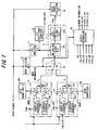
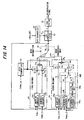
- Fig. 6 is a block diagram of a first embodiment of a voice encoding apparatus according to the present invention.
- This apparatus has the structure of a voice encoder comprising two modes, namely mode 0 and mode 1.
- the LPC analyzer 11 and LPC-coefficient quantizer 12, which are common to mode 0 and mode 1, will be described first.
- the input signal is divided into fixed-length frames on the order of 5 to 10 ms, and encoding processing is executed in frame units. It is assumed here that the number of samplings in one frame is N.
- the gain quantization method is optional and a method such as scalar quantization or vector quantization can be used.
- the LPC coefficients, rather than being quantized directly, may be quantized after first being converted to another parameter of superior quantization characteristic and interpolation characteristic, such as a k parameter (reflection coefficient) or LSP (line-spectrum pair).
- the transfer function H(z) of an LPC synthesis filter 13a constructing the auditory weighting LPC filter 13 is given by the following equation: It is possible for a filter of any type to be used as an auditory weighting filter 13b. A filter indicated by Equation (3) can be used.
- the first encoder 14, which operates in accordance with mode 0 has the same structure as that used in ordinary CELP, includes the adaptive codebook 14a, algebraic codebook 14b, gain multipliers 14c, 14d, an adder 14e and a gain quantizer 14h, and obtains (1) optimum pitch lag Lag, (2) an algebraic codebook index index_C1 and (3) a gain index index_g1.
- the search method of the adaptive codebook 14a and the search method of the algebraic codebook 14b in mode 0 are the same as the methods described in the section (A) above relating to an overview of the present invention.
- Equation (21) The first term on the right side of Equation (21) signifies placement of pulse s 0 at pulse position m 0 in pulse-system group 0, the second term on the right side signifies placement of pulse s 1 at pulse position m 1 in pulse-system group 1, and the third term on the right side signifies placement of pulse s 2 at pulse position m 2 in pulse-system group 2.
- the pulsed output signal of Equation (21) is output successively and a search is conducted for the optimum pulsed signal.
- the gain quantizer 14h quantizes pitch gain an algebraic codebook gain.
- the sound-source vector e 0 is input to the weighting filter 13b and the output thereof is input to the LPC synthesis filter 13a, whereby a weighted synthesized output syn 0 is created.
- the error-power evaluation unit 18 of mode 0 calculates error power err0 between the input signal x and output syn 0 of the LPC synthesis filter and inputs the error power to the
- the adaptive codebook 15a does not execute search processing, regards optimum pitch lag lag_old, which was obtained in a past frame (e.g., the preceding frame), as optimum lag of the present frame and finds the optimum pitch gain ⁇ 1 .
- the optimum pitch gain can be calculated in accordance with Equation (6).
- the number of pulses can be made 5 in the pulse placement of the algebraic codebook 15b, as shown in Fig. 3.
- the algebraic codebook index Index_C1 and gain index Index_g1 are obtained by successively outputting C 1 (n) expressed by Equation (23).
- the method of searching the algebraic codebook 15b is the same as the method described in the section (A) above relating to an overview of the present invention.
- the mode decision unit 19 compares err0 and err1 and decides that the mode which will finally be used is that which provides the smaller error power.
- the state of the adaptive codebook is updated before the input signal of the next frame is processed.
- state updating the oldest frame (the frame farthest in the past) of the sound-source signal in the adaptive codebook is discarded and the latest sound-source signal e x (the above-mentioned e 0 or e 1 ) found in the present frame is stored.
- the initial state of the adaptive codebook is assumed to be the zero state, i.e., a state in which the amplitudes of all samples are zero.
- the conventional CELP mode mode 0
- mode 1 a mode in which the pitch-lag information is reduced by using past pitch lag and the amount of information of an algebraic codebook is increased by the amount of reduction.
- Fig. 7 is a block diagram of a second embodiment of a voice encoding apparatus, in which components identical with those of the first embodiment shown in Fig. 6 are designated by like reference characters.
- an adaptive codebook search and an algebraic codebook search are executed in each mode, the mode that affords the smaller error is decided upon as the mode finally used, the pitch lag Lag_opt, algebraic codebook index Index_C and the gain index Index_g found in this mode are selected and these are transmitted to the decoder.
- the properties of the input signal are investigated before the search, which mode is to be adopted is decided in accordance with these properties, and encoding is executed by conducting the adaptive codebook search / algebraic codebook search in whichever mode has been adopted.
- the second embodiment differs from the first embodiment in that:
- the mode decision unit 31 investigates the properties of the input signal x and generates mode information indicating which of the modes 0, 1 should be adopted in accordance with these properties.
- the mode information becomes 0 if mode 0 is determined to be optimum and becomes mode 1 if mode 1 is determined to be optimum.
- the mode-output selector 32 selects the output of the first encoder 14 or the output of the second encoder 15.
- a method of detecting a change in open-loop lag can be used as the method of rendering the mode decision.
- Fig. 8 shows the processing flow for deciding the mode adopted based upon the properties of the input signal.
- step 102 the k for which the autocorrelation function R(k) is maximized is found (step 102).
- Lag k that prevails when the autocorrelation function R(k) is maximized is referred to as "open-loop lag" and is represented by L.
- Open-loop lag found similarly in the preceding frame shall be denoted L_old.
- L_old Open-loop lag found similarly in the preceding frame
- L_old Open-loop lag found similarly in the preceding frame
- step 103 finds the difference (L_old - L) between open-loop lag L_old of the preceding frame and open-loop lag L of the present frame (step 103). If (L_old - L) is greater than a predetermined threshold value, then it is construed that the periodicity of input voice has undergone a large change and, hence, the mode information is set to 0.
- (L_old - L) is less than the predetermined threshold value, then it is construed that the periodicity of input voice has not changed as compared with the preceding frame and, hence, the mode information is set to 1 (step 104).
- the above-described processing is thenceforth repeated frame by frame. Furthermore, following the end of mode decision, the open-loop lag L found in the present frame is retained as L_old in order to render the mode decision for the next frame.
- the mode-output selector 32 selects a terminal 0 if the mode information is 0 and selects a terminal 1 if the mode information is 1. Accordingly, the two modes do not function simultaneously in the same frame.
- the first encoder 14 conducts a search of the adaptive codebook 14a and of algebraic codebook 14b, after which quantization of pitch gain ⁇ 0 and algebraic codebook gain ⁇ 0 is executed by the gain quantizer 14h.
- the second encoder conforming to mode 1 does not operate at this time.
- the second encoder 15 does not conduct an adaptive codebook search, regards optimum pitch lag lag_old found in a past frame (e.g., the preceding frame) as the optimum lag of the present frame and obtains the optimum pitch gain ⁇ 1 that prevails at this time.
- the second encoder 15 conducts an algebraic codebook search using the algebraic codebook 15b and decides the optimum index I 1 and optimum gain ⁇ 1 that specify the pulsed signal for which error power is minimized.
- a gain quantizer 15h then executes quantization of the pitch gain ⁇ 1 and algebraic codebook gain ⁇ 1 .
- the first encoder 14 on the side of mode 0 does not operate at this time.
- mode encoding in which mode encoding is to be performed is decided based upon the properties of the input signal before a codebook search, encoding is performed in this mode and the result is output.
- encoding is performed in this mode and the result is output.
- Fig. 9 is a block diagram of a third embodiment of a voice encoding apparatus, in which components identical with those of the first embodiment shown in Fig. 6 are designated by like reference characters. This embodiment differs from the first embodiment in that:
- the first encoder 14 obtains optimum pitch lag Lag, the algebraic codebook index Index_C0 and the gain index Index_g0 by processing exactly the same as that of the first embodiment.
- the second encoder 15 does not conduct a search of the adaptive codebook 15a and uses the optimum pitch lag Lag_old, which was decided in a past frame (e.g., the preceding frame), as the optimum pitch lag of the present frame in a manner similar to that of the first embodiment.
- the optimum pitch gain is calculated in accordance with Equation (6).
- the second encoder 15 conducts the search using the first algebraic codebook 15b 1 or second algebraic codebook 15b 2 , depending upon the value of the pitch lag Lag_old.
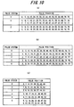
- Equation (21) An example of pulse placement of the algebraic codebook 14b used in mode 0 is illustrated in Fig. 10(a). This pulse placement is that for a case where the number of pulses is three and the number of quantization bits is 17.
- the first algebraic codebook 15b 1 has this pulse placement and successively outputs pulsed signals having a pulse of a positive polarity or negative polarity at sampling points extracted one at a time from each of the pulse-system groups. Further, an example of pulse placement in a case where six pulses reside in a period of time shorter than the duration of one frame at 25 bits is as shown in (c) of Fig. 10.
- the second algebraic codebook 15b 2 has this pulse placement and successively outputs pulsed signals having a pulse of a positive polarity or negative polarity at sampling points extracted one at a time from each of the pulse-system groups.
- the pulse placement of (b) of Fig. 10 is such that the number of pulses per frame is two greater in comparison with (a) of Fig. 10.
- the pulse placement of (c) of Fig. 10 is such that the pulses are placed over a narrow range (sampling points 0 to 55); there are three more pulses in comparison with (a) of Fig. 10. In mode 1, therefore, it is possible to encode a sound-source signal more precisely than in mode 0.
- the second algebraic codebook 15b 2 places pulses over a range (sampling points 0 to 55) narrower than that of the first algebraic codebook 15b 1 but the number of pulses is greater.
- the second algebraic codebook 15b 2 is capable of encoding the sound-source signal more precisely than the first algebraic codebook 15b 1 .
- mode 1 therefore, if the periodicity of the input signal x is short, a pulsed signal, which is the noise component, is generated using the second algebraic codebook 15b 2 . If the periodicity of the input signal x is long, then a pulsed signal that is the noise component is generated using the first algebraic codebook 15b 2 .
- a search is conducted using the second algebraic codebook 15b 2 .
- the method of searching the second algebraic codebook 15b 2 may be similar to the algebraic codebook search already described, though it is required that impulse response be subjected to pitch periodization before search processing is executed.
- the pitch periodization method will not be only simple repetition; repetition may be performed while decreasing or increasing Lag_old-number of the leading samples at a fixed rate.
- Fig. 11 is a conceptual view of pitch periodization by the pitch periodizing unit 15g, in which (1) represents a pulsed signal, namely a noise component, prior to the pitch periodization, and (2) represents the pulsed signal after the pitch periodization.
- the pulsed signal after pitch periodization is obtained by repeating (copying) a noise component A of an amount commensurate with pitch lag Lag_old before pitch periodization.
- the pitch periodization method will not be only simple repetition; repetition may be performed while decreasing or increasing Lag_old-number of the leading samples at a fixed rate.
- the algebraic codebook changeover unit 15f connects a switch Sw to a terminal Sa if the value of past pitch lag Lag_old is greater than the threshold value Th, whereby the pulsed signal output from the first algebraic codebook 15b 1 is input to the gain multiplier 15d. The latter multiplies the input signal by the algebraic codebook gain ⁇ 1 . Further, the algebraic codebook changeover unit 15f connects the switch Sw to a terminal Sb if the value of past pitch lag Lag_old is less than the threshold value Th, whereby the pulsed signal output from the first algebraic codebook 15b 1 , which signal has undergone pitch periodization by the pitch periodizing unit 15g, is input to the gain multiplier 15d. The latter multiplies the input signal by the algebraic codebook gain ⁇ 1 .
- the third embodiment is as set forth above.
- the number of quantization bits and pulse placements illustrated in this embodiment are examples, and various numbers of quantization bits and various pulse placements are possible. Further, though two encoding modes have been described in this embodiment, three or more modes may be used.
- two weighting filters two LPC synthesis filters and two error-power evaluation units are used.
- these pairs of devices can be united into single common devices and the inputs to the filters may be switched.
- the number of pulses and pulse placement are changed over adaptively in accordance with the value of past pitch lag, thereby making it possible to perform encoding more precisely in comparison with conventional voice encoding and to obtain high-quality reconstructed speech.
- Fig. 12 is a block diagram of a fourth embodiment of a voice encoding apparatus.
- the properties of the input signal are investigated prior to a search, which mode of modes 0, 1 is to be adopted is decided in accordance with these properties, and encoding is performed by conducting the adaptive codebook search / algebraic codebook search in whichever mode has been adopted.
- the fourth embodiment differs from the third embodiment in that:
- the mode decision processing executed by the mode decision unit 31 is the same as the processing shown in Fig. 8.
- mode encoding in which mode encoding is to be performed is decided based upon the properties of the input signal before a codebook search, encoding is performed in this mode and the result is output.
- encoding is performed in this mode and the result is output.
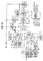
- Fig. 13 is a block diagram of a first embodiment of a voice decoding apparatus. This apparatus generates a voice signal by decoding code information sent from the voice encoding apparatus (of the first and second embodiments).
- An LPC synthesis filter 52 is a filter having a transfer characteristic indicated by the following equation using the LPC coefficient ⁇ q (i):
- a first decoder 53 corresponds to the first encoder 14 in the voice encoding apparatus and includes an adaptive codebook 53a, an algebraic codebook 53b, gain multipliers 53c, 53d and an adder 53e.
- the algebraic codebook 53b has the pulse placement shown in Fig. 2.
- a second first decoder 54 corresponds to the second encoder 15 in the voice encoding apparatus and includes an adaptive codebook 54a, an algebraic codebook 54b, gain multipliers 54c, 54d and an adder 54e.
- the algebraic codebook 54b has the pulse placement shown in Fig. 3.
- the pitch lag Lag enters the adaptive codebook 53a of the first decoder and 80 samples of a pitch-period component (adaptive codebook vector) P 0 corresponding to this pitch lag Lag are output by the adaptive codebook 53a. Further, the algebraic codebook index Index_C enters the algebraic codebook 53b of the first decoder and the corresponding noise component (algebraic codebook vector) C 0 is output.
- the algebraic codebook vector C 0 is generated in accordance with Equation (21).
- the gain index Index_g enters a gain dequantizer 55 and the dequantized value ⁇ 0 of pitch gain and dequantized value ⁇ 0 of algebraic codebook gain enter the multipliers 53c, 53d from the gain dequantizer 55.
- the pitch lag Lag_old of the preceding frame enters the adaptive codebook 54a of the second decoder and 80 samples of a pitch-period component (adaptive codebook vector) P 1 corresponding to this pitch lag Lag_old are output by the adaptive codebook 54a.
- the algebraic codebook index Index_C enters the algebraic codebook 54b of the second decoder and the corresponding noise component (algebraic codebook vector) C 1 (n) is generated in accordance with Equation (25).
- the gain index Index_g enters the gain dequantizer 55 and the dequantized value ⁇ 1 of pitch gain and dequantized value ⁇ 1 of algebraic codebook gain enter the multipliers 54c, 54d from the gain dequantizer 55.
- a mode changeover unit 56 changes over a switch Sw2 in accordance with the mode information. Specifically, Sw2 is connected to a terminal 0 if the mode information is 0, whereby e 0 becomes the sound-source signal ex. If the mode information is 1, then the switch Sw2 is connected to terminal 1 so that e 1 becomes the sound-source signal ex.
- the sound-source signal ex is input to the adaptive codebooks 53a, 54a to update the content thereof. That is, the sound-source signal of the oldest frame in the adaptive codebook is discarded and the latest sound-source signal ex found in the present frame is stored.
- the sound-source signal ex is input to the LPC synthesis filter 52 constituted by the LPC quantization coefficient ⁇ q (i), and the LPC synthesis filter 52 outputs an LPC-synthesized output y.
- the LPC-synthesized output y may be output as reconstructed speech, it is preferred that this signal be passed through a post filter 57 in order to enhance sound quality.
- the post filter 57 may be of any structure.
- the number of pulses and pulse placement are changed over adaptively in accordance with the value of past pitch lag, thereby making it possible to obtain reconstructed speech of a quality higher than that of the conventional voice decoding apparatus.
- Fig. 14 is a block diagram of a second embodiment of a voice decoding apparatus.
- This apparatus generates a voice signal by decoding code information sent from the voice encoding apparatus (of the third and fourth embodiments).
- Components identical with those of the first embodiment in Fig. 13 are designated by like reference characters.
- This embodiment differs from the first embodiment in that:
- the mode information is 0, decoding processing exactly the same as that of the first embodiment is executed.
- the mode information is 1, on the other hand, if pitch lag Lag_old of the preceding frame is greater than the predetermined threshold value Th (e.g., 55), the algebraic codebook index Index_C enters the first algebraic codebook 54b 1 and a codebook output C 1 (n) is generated in accordance with Equation (25). If pitch lag Lag_old is less than the predetermined threshold value Th, then the algebraic codebook index Index_C enters the first algebraic codebook 54b 2 and a codebook output C 1 (n) is generated in accordance with Equation (27). Decoding processing identical with that of the first embodiment is thenceforth executed and a reconstructed speech signal is output from the post filter 57.
- Th e.g. 55
- the number of pulses and pulse placement are changed over adaptively in accordance with the value of past pitch lag, thereby making it possible to obtain reconstructed speech of a quality higher than that of the conventional voice decoding apparatus.
- the conventional CELP mode mode 0
- mode 1 a mode in which, by using past pitch lag, the pitch-lag information necessary for an adaptive codebook is reduced while the amount of information in an algebraic codebook is increased.
Landscapes
- Engineering & Computer Science (AREA)
- Physics & Mathematics (AREA)
- Multimedia (AREA)
- Health & Medical Sciences (AREA)
- Audiology, Speech & Language Pathology (AREA)
- Human Computer Interaction (AREA)
- Signal Processing (AREA)
- Acoustics & Sound (AREA)
- Computational Linguistics (AREA)
- Algebra (AREA)
- General Physics & Mathematics (AREA)
- Mathematical Analysis (AREA)
- Mathematical Optimization (AREA)
- Mathematical Physics (AREA)
- Pure & Applied Mathematics (AREA)
- Theoretical Computer Science (AREA)
- Compression, Expansion, Code Conversion, And Decoders (AREA)
Applications Claiming Priority (1)
| Application Number | Priority Date | Filing Date | Title |
|---|---|---|---|
| PCT/JP1999/004991 WO2001020595A1 (fr) | 1999-09-14 | 1999-09-14 | Codeur/decodeur vocal |
Publications (3)
| Publication Number | Publication Date |
|---|---|
| EP1221694A1 true EP1221694A1 (fr) | 2002-07-10 |
| EP1221694A4 EP1221694A4 (fr) | 2005-06-22 |
| EP1221694B1 EP1221694B1 (fr) | 2006-07-19 |
Family
ID=14236705
Family Applications (1)
| Application Number | Title | Priority Date | Filing Date |
|---|---|---|---|
| EP99943314A Expired - Lifetime EP1221694B1 (fr) | 1999-09-14 | 1999-09-14 | Codeur/decodeur vocal |
Country Status (5)
| Country | Link |
|---|---|
| US (1) | US6594626B2 (fr) |
| EP (1) | EP1221694B1 (fr) |
| JP (1) | JP4005359B2 (fr) |
| DE (1) | DE69932460T2 (fr) |
| WO (1) | WO2001020595A1 (fr) |
Cited By (6)
| Publication number | Priority date | Publication date | Assignee | Title |
|---|---|---|---|---|
| US7817677B2 (en) | 2004-08-30 | 2010-10-19 | Qualcomm Incorporated | Method and apparatus for processing packetized data in a wireless communication system |
| US8085678B2 (en) | 2004-10-13 | 2011-12-27 | Qualcomm Incorporated | Media (voice) playback (de-jitter) buffer adjustments based on air interface |
| US8155965B2 (en) | 2005-03-11 | 2012-04-10 | Qualcomm Incorporated | Time warping frames inside the vocoder by modifying the residual |
| US8355907B2 (en) | 2005-03-11 | 2013-01-15 | Qualcomm Incorporated | Method and apparatus for phase matching frames in vocoders |
| US8600739B2 (en) | 2007-11-05 | 2013-12-03 | Huawei Technologies Co., Ltd. | Coding method, encoder, and computer readable medium that uses one of multiple codebooks based on a type of input signal |
| US8723700B2 (en) | 2009-06-19 | 2014-05-13 | Huawei Technologies Co., Ltd. | Method and device for pulse encoding, method and device for pulse decoding |
Families Citing this family (27)
| Publication number | Priority date | Publication date | Assignee | Title |
|---|---|---|---|---|
| US7457415B2 (en) | 1998-08-20 | 2008-11-25 | Akikaze Technologies, Llc | Secure information distribution system utilizing information segment scrambling |
| US6934677B2 (en) | 2001-12-14 | 2005-08-23 | Microsoft Corporation | Quantization matrices based on critical band pattern information for digital audio wherein quantization bands differ from critical bands |
| US7240001B2 (en) * | 2001-12-14 | 2007-07-03 | Microsoft Corporation | Quality improvement techniques in an audio encoder |
| JP2005520206A (ja) * | 2002-03-12 | 2005-07-07 | ディリチウム ネットワークス ピーティーワイ リミテッド | オーディオ・トランスコーダにおける適応コードブック・ピッチ・ラグ計算方法 |
| US7502743B2 (en) | 2002-09-04 | 2009-03-10 | Microsoft Corporation | Multi-channel audio encoding and decoding with multi-channel transform selection |
| JP4676140B2 (ja) | 2002-09-04 | 2011-04-27 | マイクロソフト コーポレーション | オーディオの量子化および逆量子化 |
| US7299190B2 (en) * | 2002-09-04 | 2007-11-20 | Microsoft Corporation | Quantization and inverse quantization for audio |
| KR100463417B1 (ko) * | 2002-10-10 | 2004-12-23 | 한국전자통신연구원 | 상관함수의 최대값과 그의 후보값의 비를 이용한 피치검출 방법 및 그 장치 |
| JP2004157381A (ja) * | 2002-11-07 | 2004-06-03 | Hitachi Kokusai Electric Inc | 音声符号化装置及び方法 |
| KR100465316B1 (ko) * | 2002-11-18 | 2005-01-13 | 한국전자통신연구원 | 음성 부호화기 및 이를 이용한 음성 부호화 방법 |
| US7698132B2 (en) * | 2002-12-17 | 2010-04-13 | Qualcomm Incorporated | Sub-sampled excitation waveform codebooks |
| TWI225637B (en) * | 2003-06-09 | 2004-12-21 | Ali Corp | Method for calculation a pitch period estimation of speech signals with variable step size |
| WO2005020210A2 (fr) * | 2003-08-26 | 2005-03-03 | Sarnoff Corporation | Procede et appareil pour codage audio a debit binaire variable adaptatif |
| US20050091047A1 (en) * | 2003-10-27 | 2005-04-28 | Gibbs Jonathan A. | Method and apparatus for network communication |
| JP4789430B2 (ja) * | 2004-06-25 | 2011-10-12 | パナソニック株式会社 | 音声符号化装置、音声復号化装置、およびこれらの方法 |
| US7539612B2 (en) * | 2005-07-15 | 2009-05-26 | Microsoft Corporation | Coding and decoding scale factor information |
| WO2007105586A1 (fr) * | 2006-03-10 | 2007-09-20 | Matsushita Electric Industrial Co., Ltd. | Dispositif et procede de codage |
| US8712766B2 (en) * | 2006-05-16 | 2014-04-29 | Motorola Mobility Llc | Method and system for coding an information signal using closed loop adaptive bit allocation |
| US20090240494A1 (en) * | 2006-06-29 | 2009-09-24 | Panasonic Corporation | Voice encoding device and voice encoding method |
| US8364492B2 (en) * | 2006-07-13 | 2013-01-29 | Nec Corporation | Apparatus, method and program for giving warning in connection with inputting of unvoiced speech |
| CN101226744B (zh) * | 2007-01-19 | 2011-04-13 | 华为技术有限公司 | 语音解码器中实现语音解码的方法及装置 |
| WO2009033288A1 (fr) * | 2007-09-11 | 2009-03-19 | Voiceage Corporation | Procédé et dispositif de recherche dans un livre de codes algébriques lors d'un codage vocal ou audio |
| JP4490507B2 (ja) * | 2008-09-26 | 2010-06-30 | パナソニック株式会社 | 音声分析装置および音声分析方法 |
| JP5320508B2 (ja) * | 2010-07-16 | 2013-10-23 | 日本電信電話株式会社 | 符号化装置、復号装置、これらの方法、プログラム及び記録媒体 |
| CN102623012B (zh) | 2011-01-26 | 2014-08-20 | 华为技术有限公司 | 矢量联合编解码方法及编解码器 |
| KR101542370B1 (ko) | 2011-02-16 | 2015-08-12 | 니폰 덴신 덴와 가부시끼가이샤 | 부호화 방법, 복호 방법, 부호화 장치, 복호 장치, 프로그램, 및 기록 매체 |
| WO2013176177A1 (fr) * | 2012-05-23 | 2013-11-28 | 日本電信電話株式会社 | Procédé de codage, procédé de décodage, dispositif de codage, dispositif de décodage, programme et support d'enregistrement |
Citations (1)
| Publication number | Priority date | Publication date | Assignee | Title |
|---|---|---|---|---|
| US5734789A (en) * | 1992-06-01 | 1998-03-31 | Hughes Electronics | Voiced, unvoiced or noise modes in a CELP vocoder |
Family Cites Families (25)
| Publication number | Priority date | Publication date | Assignee | Title |
|---|---|---|---|---|
| JP2940005B2 (ja) * | 1989-07-20 | 1999-08-25 | 日本電気株式会社 | 音声符号化装置 |
| DE69133296T2 (de) * | 1990-02-22 | 2004-01-29 | Nec Corp | Sprachcodierer |
| US5754976A (en) * | 1990-02-23 | 1998-05-19 | Universite De Sherbrooke | Algebraic codebook with signal-selected pulse amplitude/position combinations for fast coding of speech |
| US5701392A (en) * | 1990-02-23 | 1997-12-23 | Universite De Sherbrooke | Depth-first algebraic-codebook search for fast coding of speech |
| JP2538450B2 (ja) | 1991-07-08 | 1996-09-25 | 日本電信電話株式会社 | 音声の励振信号符号化・復号化方法 |
| US5396576A (en) * | 1991-05-22 | 1995-03-07 | Nippon Telegraph And Telephone Corporation | Speech coding and decoding methods using adaptive and random code books |
| JPH05167457A (ja) * | 1991-12-19 | 1993-07-02 | Matsushita Electric Ind Co Ltd | 音声符号化装置 |
| JP2774003B2 (ja) * | 1991-12-24 | 1998-07-09 | 沖電気工業株式会社 | コード励振線形予測符号化装置 |
| JP3057907B2 (ja) * | 1992-06-16 | 2000-07-04 | 松下電器産業株式会社 | 音声符号化装置 |
| DE69309557T2 (de) * | 1992-06-29 | 1997-10-09 | Nippon Telegraph & Telephone | Verfahren und Vorrichtung zur Sprachkodierung |
| JP2779886B2 (ja) * | 1992-10-05 | 1998-07-23 | 日本電信電話株式会社 | 広帯域音声信号復元方法 |
| JP3230782B2 (ja) | 1993-08-17 | 2001-11-19 | 日本電信電話株式会社 | 広帯域音声信号復元方法 |
| JP3199142B2 (ja) | 1993-09-22 | 2001-08-13 | 日本電信電話株式会社 | 音声の励振信号符号化方法および装置 |
| DE69426860T2 (de) * | 1993-12-10 | 2001-07-19 | Nec Corp | Sprachcodierer und Verfahren zum Suchen von Codebüchern |
| US5684920A (en) * | 1994-03-17 | 1997-11-04 | Nippon Telegraph And Telephone | Acoustic signal transform coding method and decoding method having a high efficiency envelope flattening method therein |
| FR2729245B1 (fr) * | 1995-01-06 | 1997-04-11 | Lamblin Claude | Procede de codage de parole a prediction lineaire et excitation par codes algebriques |
| JP3235703B2 (ja) * | 1995-03-10 | 2001-12-04 | 日本電信電話株式会社 | ディジタルフィルタのフィルタ係数決定方法 |
| JP3471542B2 (ja) * | 1996-10-31 | 2003-12-02 | 日本電気株式会社 | 音声符号化装置 |
| JP3174742B2 (ja) * | 1997-02-19 | 2001-06-11 | 松下電器産業株式会社 | Celp型音声復号化装置及びcelp型音声復号化方法 |
| WO1998020483A1 (fr) * | 1996-11-07 | 1998-05-14 | Matsushita Electric Industrial Co., Ltd. | Generateur de vecteur de source sonore, codeur et decodeur vocal |
| US6345246B1 (en) * | 1997-02-05 | 2002-02-05 | Nippon Telegraph And Telephone Corporation | Apparatus and method for efficiently coding plural channels of an acoustic signal at low bit rates |
| US6073092A (en) * | 1997-06-26 | 2000-06-06 | Telogy Networks, Inc. | Method for speech coding based on a code excited linear prediction (CELP) model |
| US6014618A (en) * | 1998-08-06 | 2000-01-11 | Dsp Software Engineering, Inc. | LPAS speech coder using vector quantized, multi-codebook, multi-tap pitch predictor and optimized ternary source excitation codebook derivation |
| US6330533B2 (en) * | 1998-08-24 | 2001-12-11 | Conexant Systems, Inc. | Speech encoder adaptively applying pitch preprocessing with warping of target signal |
| US6295520B1 (en) * | 1999-03-15 | 2001-09-25 | Tritech Microelectronics Ltd. | Multi-pulse synthesis simplification in analysis-by-synthesis coders |
-
1999
- 1999-09-14 EP EP99943314A patent/EP1221694B1/fr not_active Expired - Lifetime
- 1999-09-14 DE DE69932460T patent/DE69932460T2/de not_active Expired - Lifetime
- 1999-09-14 WO PCT/JP1999/004991 patent/WO2001020595A1/fr active IP Right Grant
- 1999-09-14 JP JP2001524094A patent/JP4005359B2/ja not_active Expired - Fee Related
-
2002
- 2002-01-08 US US10/046,125 patent/US6594626B2/en not_active Expired - Lifetime
Patent Citations (1)
| Publication number | Priority date | Publication date | Assignee | Title |
|---|---|---|---|---|
| US5734789A (en) * | 1992-06-01 | 1998-03-31 | Hughes Electronics | Voiced, unvoiced or noise modes in a CELP vocoder |
Non-Patent Citations (2)
| Title |
|---|
| See also references of WO0120595A1 * |
| WOODARD J ET AL: "A DUAL-RATE ALGEBRAIC CELP-BASED SPEECH TRANSCEIVER" PROCEEDINGS OF THE VEHICULAR TECHNOLOGY CONFERENCE. STOCKHOLM, JUNE 8, vol. VOL. 3 CONF. 44, 8 June 1994 (1994-06-08), pages 1690-1694, XP000497710 ISBN: 0-7803-1928-1 * |
Cited By (11)
| Publication number | Priority date | Publication date | Assignee | Title |
|---|---|---|---|---|
| US7817677B2 (en) | 2004-08-30 | 2010-10-19 | Qualcomm Incorporated | Method and apparatus for processing packetized data in a wireless communication system |
| US7826441B2 (en) | 2004-08-30 | 2010-11-02 | Qualcomm Incorporated | Method and apparatus for an adaptive de-jitter buffer in a wireless communication system |
| US7830900B2 (en) | 2004-08-30 | 2010-11-09 | Qualcomm Incorporated | Method and apparatus for an adaptive de-jitter buffer |
| US8331385B2 (en) | 2004-08-30 | 2012-12-11 | Qualcomm Incorporated | Method and apparatus for flexible packet selection in a wireless communication system |
| US8085678B2 (en) | 2004-10-13 | 2011-12-27 | Qualcomm Incorporated | Media (voice) playback (de-jitter) buffer adjustments based on air interface |
| US8155965B2 (en) | 2005-03-11 | 2012-04-10 | Qualcomm Incorporated | Time warping frames inside the vocoder by modifying the residual |
| US8355907B2 (en) | 2005-03-11 | 2013-01-15 | Qualcomm Incorporated | Method and apparatus for phase matching frames in vocoders |
| US8600739B2 (en) | 2007-11-05 | 2013-12-03 | Huawei Technologies Co., Ltd. | Coding method, encoder, and computer readable medium that uses one of multiple codebooks based on a type of input signal |
| US8723700B2 (en) | 2009-06-19 | 2014-05-13 | Huawei Technologies Co., Ltd. | Method and device for pulse encoding, method and device for pulse decoding |
| US9349381B2 (en) | 2009-06-19 | 2016-05-24 | Huawei Technologies Co., Ltd | Method and device for pulse encoding, method and device for pulse decoding |
| US10026412B2 (en) | 2009-06-19 | 2018-07-17 | Huawei Technologies Co., Ltd. | Method and device for pulse encoding, method and device for pulse decoding |
Also Published As
| Publication number | Publication date |
|---|---|
| US6594626B2 (en) | 2003-07-15 |
| DE69932460T2 (de) | 2007-02-08 |
| US20020111800A1 (en) | 2002-08-15 |
| EP1221694B1 (fr) | 2006-07-19 |
| EP1221694A4 (fr) | 2005-06-22 |
| JP4005359B2 (ja) | 2007-11-07 |
| DE69932460D1 (de) | 2006-08-31 |
| WO2001020595A1 (fr) | 2001-03-22 |
Similar Documents
| Publication | Publication Date | Title |
|---|---|---|
| EP1221694B1 (fr) | Codeur/decodeur vocal | |
| US5602961A (en) | Method and apparatus for speech compression using multi-mode code excited linear predictive coding | |
| EP1224662B1 (fr) | Codage de la parole a debit binaire variable de type celp avec classification phonetique | |
| EP0409239B1 (fr) | Procédé pour le codage et le décodage de la parole | |
| EP1619664B1 (fr) | Appareil de codage et de décodage de la parole et méthodes pour cela | |
| JP3996213B2 (ja) | 入力標本列処理方法 | |
| EP0514912B1 (fr) | Procédés de codage et décodage de parole | |
| US5140638A (en) | Speech coding system and a method of encoding speech | |
| EP0802524B1 (fr) | Codeur de parole | |
| EP0898267B1 (fr) | Système de codage de la parole | |
| EP1062661B1 (fr) | Codage de la parole | |
| US20090112581A1 (en) | Method and apparatus for transmitting an encoded speech signal | |
| AU6397094A (en) | Vector quantizer method and apparatus | |
| JPH0990995A (ja) | 音声符号化装置 | |
| EP0654909A1 (fr) | Codeur-decodeur predictif lineaire a excitation par codes | |
| EP1096476B1 (fr) | Décodage de la parole | |
| EP0865027B1 (fr) | Méthode de codage du vecteur composant aléatoire dans un codeur ACELP | |
| EP1513137A1 (fr) | Système de traitement de la parole à excitation à impulsions multiples | |
| EP0778561B1 (fr) | Dispositif de codage de la parole | |
| EP0557940B1 (fr) | Système de codage de la parole | |
| JPH09319398A (ja) | 信号符号化装置 | |
| JPH0944195A (ja) | 音声符号化装置 | |
| EP1187337B1 (fr) | Processeur de codage de parole et procede de codage de parole | |
| US6098037A (en) | Formant weighted vector quantization of LPC excitation harmonic spectral amplitudes | |
| JP2003044099A (ja) | ピッチ周期探索範囲設定装置及びピッチ周期探索装置 |
Legal Events
| Date | Code | Title | Description |
|---|---|---|---|
| PUAI | Public reference made under article 153(3) epc to a published international application that has entered the european phase |
Free format text: ORIGINAL CODE: 0009012 |
|
| 17P | Request for examination filed |
Effective date: 20020115 |
|
| AK | Designated contracting states |
Kind code of ref document: A1 Designated state(s): AT BE CH CY DE DK ES FI FR GB GR IE IT LI LU MC NL PT SE |
|
| RIC1 | Information provided on ipc code assigned before grant |
Free format text: 7G 10L 9/14 A |
|
| RBV | Designated contracting states (corrected) |
Designated state(s): DE FR GB |
|
| A4 | Supplementary search report drawn up and despatched |
Effective date: 20050506 |
|
| RIC1 | Information provided on ipc code assigned before grant |
Ipc: 7G 10L 19/10 B Ipc: 7G 10L 19/08 B Ipc: 7G 10L 19/14 A |
|
| 17Q | First examination report despatched |
Effective date: 20050622 |
|
| GRAP | Despatch of communication of intention to grant a patent |
Free format text: ORIGINAL CODE: EPIDOSNIGR1 |
|
| GRAS | Grant fee paid |
Free format text: ORIGINAL CODE: EPIDOSNIGR3 |
|
| GRAA | (expected) grant |
Free format text: ORIGINAL CODE: 0009210 |
|
| AK | Designated contracting states |
Kind code of ref document: B1 Designated state(s): DE FR GB |
|
| REG | Reference to a national code |
Ref country code: GB Ref legal event code: FG4D |
|
| REF | Corresponds to: |
Ref document number: 69932460 Country of ref document: DE Date of ref document: 20060831 Kind code of ref document: P |
|
| ET | Fr: translation filed | ||
| PLBE | No opposition filed within time limit |
Free format text: ORIGINAL CODE: 0009261 |
|
| STAA | Information on the status of an ep patent application or granted ep patent |
Free format text: STATUS: NO OPPOSITION FILED WITHIN TIME LIMIT |
|
| 26N | No opposition filed |
Effective date: 20070420 |
|
| REG | Reference to a national code |
Ref country code: FR Ref legal event code: PLFP Year of fee payment: 17 |
|
| PGFP | Annual fee paid to national office [announced via postgrant information from national office to epo] |
Ref country code: GB Payment date: 20150909 Year of fee payment: 17 Ref country code: DE Payment date: 20150908 Year of fee payment: 17 |
|
| PGFP | Annual fee paid to national office [announced via postgrant information from national office to epo] |
Ref country code: FR Payment date: 20150811 Year of fee payment: 17 |
|
| REG | Reference to a national code |
Ref country code: DE Ref legal event code: R119 Ref document number: 69932460 Country of ref document: DE |
|
| GBPC | Gb: european patent ceased through non-payment of renewal fee |
Effective date: 20160914 |
|
| REG | Reference to a national code |
Ref country code: FR Ref legal event code: ST Effective date: 20170531 |
|
| PG25 | Lapsed in a contracting state [announced via postgrant information from national office to epo] |
Ref country code: DE Free format text: LAPSE BECAUSE OF NON-PAYMENT OF DUE FEES Effective date: 20170401 Ref country code: FR Free format text: LAPSE BECAUSE OF NON-PAYMENT OF DUE FEES Effective date: 20160930 Ref country code: GB Free format text: LAPSE BECAUSE OF NON-PAYMENT OF DUE FEES Effective date: 20160914 |