EP1221528B1 - Fire-resistant glazing - Google Patents
Fire-resistant glazing Download PDFInfo
- Publication number
- EP1221528B1 EP1221528B1 EP01100432A EP01100432A EP1221528B1 EP 1221528 B1 EP1221528 B1 EP 1221528B1 EP 01100432 A EP01100432 A EP 01100432A EP 01100432 A EP01100432 A EP 01100432A EP 1221528 B1 EP1221528 B1 EP 1221528B1
- Authority
- EP
- European Patent Office
- Prior art keywords
- spacer
- glazing
- fire
- fire protective
- fire protection
- Prior art date
- Legal status (The legal status is an assumption and is not a legal conclusion. Google has not performed a legal analysis and makes no representation as to the accuracy of the status listed.)
- Expired - Lifetime
Links
Images


Classifications
-
- E—FIXED CONSTRUCTIONS
- E06—DOORS, WINDOWS, SHUTTERS, OR ROLLER BLINDS IN GENERAL; LADDERS
- E06B—FIXED OR MOVABLE CLOSURES FOR OPENINGS IN BUILDINGS, VEHICLES, FENCES OR LIKE ENCLOSURES IN GENERAL, e.g. DOORS, WINDOWS, BLINDS, GATES
- E06B5/00—Doors, windows, or like closures for special purposes; Border constructions therefor
- E06B5/10—Doors, windows, or like closures for special purposes; Border constructions therefor for protection against air-raid or other war-like action; for other protective purposes
- E06B5/16—Fireproof doors or similar closures; Adaptations of fixed constructions therefor
- E06B5/165—Fireproof windows
-
- E—FIXED CONSTRUCTIONS
- E06—DOORS, WINDOWS, SHUTTERS, OR ROLLER BLINDS IN GENERAL; LADDERS
- E06B—FIXED OR MOVABLE CLOSURES FOR OPENINGS IN BUILDINGS, VEHICLES, FENCES OR LIKE ENCLOSURES IN GENERAL, e.g. DOORS, WINDOWS, BLINDS, GATES
- E06B1/00—Border constructions of openings in walls, floors, or ceilings; Frames to be rigidly mounted in such openings
- E06B1/04—Frames for doors, windows, or the like to be fixed in openings
- E06B1/36—Frames uniquely adapted for windows
- E06B1/38—Frames uniquely adapted for windows for shop, show, or like large windows
-
- E—FIXED CONSTRUCTIONS
- E06—DOORS, WINDOWS, SHUTTERS, OR ROLLER BLINDS IN GENERAL; LADDERS
- E06B—FIXED OR MOVABLE CLOSURES FOR OPENINGS IN BUILDINGS, VEHICLES, FENCES OR LIKE ENCLOSURES IN GENERAL, e.g. DOORS, WINDOWS, BLINDS, GATES
- E06B3/00—Window sashes, door leaves, or like elements for closing wall or like openings; Layout of fixed or moving closures, e.g. windows in wall or like openings; Features of rigidly-mounted outer frames relating to the mounting of wing frames
- E06B3/54—Fixing of glass panes or like plates
- E06B3/5481—Fixing of glass panes or like plates by means of discrete fixing elements, e.g. glazing clips, glaziers points
Definitions
- the invention relates to a fire-resistant glazing of several, arranged in a common plane fire protection windows, the adjacent edges are to form a parting line at a distance from each other and are of at least one support, which is arranged at a distance from the glazing in the room and fixed to the space-limiting surfaces is, wherein the support is provided with support brackets to which the fire panels are attached.
- Such fire-resistant glazing is known from EP-B1 0 658 677.
- An essential static element of this fire-resistant glazing is a support structure made of a metal support which is arranged freely in the room at a distance from the fire-protection panes and which is fastened by its ends to the respective space-limiting surfaces.
- Such fire-resistant glazing which is located outside the glazing level freestanding in the support structure is advantageous.
- Their metatarsals are exposed in case of fire to an all-round heat effect, so that they can expand substantially uniformly and without major tension.
- temperature-induced stresses on the fire-resistant glazing can be kept low, so that even with prolonged exposure to fire and heat it shows no more pronounced bulges.
- the fire protection windows with the support brackets are each by means of two support plates connected. These clamp the respective fire protection pane between them, to which they are clamped together by screws which pass through the holes in the fire protection windows.
- the disadvantage of this construction is the fact that the production of such holes in the corner region of the fire protection is difficult, especially since fire panels are multi-layered arranged between glass layers, built up in the event of fire protective active layers containing layers, and the fire protection due to this structure critical to punctiform mechanical loads react. Particularly sensitive are fire protection windows in the edge area and here again in the corner area, which is why it should be strived to dispense as far as possible in the vicinity of these critical zones on a subsequent mechanical processing of the fire protection windows.
- a facade cladding, inter alia, for fire-resistant glazings is known in which the plates are connected to the building structure via plate holder.
- These plate holders are arranged on the horizontal edges of the facade panels and consist of two clamping plates, which are clamped together by clamping means in the form of screws. These screws are located in the joints between the facade panels and clamp the facade panels with the interposition of elastic seals between them.
- the inner clamping plate is connected to the building structure via a threaded bolt.
- the facade panels are clamped in the edge region with a certain clamping force, which leads in particular to fire in an increased mechanical load, which is unfavorable especially in the edge of fire protection windows and can lead to premature destruction.
- the invention has for its object to provide a low-voltage even in case of fire behaving fire-resistant glazing, are avoided in the critical mechanical stresses in problematic edge and corner area of the fire protection.
- the solution of this problem by the invention is characterized in that in each case a corner of four adjacent fire protection discs are held by means of a spacer in the form of a four-armed cross on each support bracket, wherein the arms of the spacer are in the parting line, the two each above the spacer arranged fire protection disks stand up on the spacer and all four fire protection panels are held laterally by a plate which covers on the side facing away from the support of the glazing part of the edge of the fire panels and is connected by a screw to the support bracket.
- the fire protection discs are with their end face over a large area on the spacer, which is connected to the respective support bracket of the support, without exerting a clamping or clamping force on the fire protection windows. Due to the large-area standing up, the mechanical load on the sensitive edge of the fire-resistant windows is significantly lower than in the prior art.
- the lateral forces acting on the fire-resistant glazing are excluded from the support bracket or the plate. Since this plate is part of the edge of the Covered fire panels, the lateral forces are removed from the plate via the support bracket on the support. At the same time the plate covers the spacer, so that this is invisible in a frontal view of the fire panel.
- the screw penetrates a central bore of the spacer.
- the transition between the arms of the spacer is rounded.
- the corners of the fire protection windows are bevelled, preferably at an angle of 45 °. In this way, it is ensured that the fire protection plate is supported exclusively flat on one of the arms of the spacer, without causing mechanical stresses in the immediate corner region of the fire protection pane.
- the plate is provided at its side facing the glazing with recesses for partially receiving the spacer.
- the construction of a fire-resistant glazing according to the invention is particularly suitable because of its simple structure and its voltage-dissipating mounting of the fire protection glass to be made entirely or partially of wood.
- the invention accordingly proposes that Support bracket and / or the support made of a wood core, which is surrounded on all sides by fire protection plates.
- the outer sides of the fire protection panels may be provided with a wooden cladding for visual reasons, so that the viewer the impression of an existing solely wooden support structure is created.
- the spacer is made of wood, preferably made of layer of glued wood.
- the wood may be pretreated in a suitable manner, for example by an impregnation increasing the flash point.
- the fire-resistant glazing shown in Fig. 1 is the translucent subdivision of two adjoining rooms and consists of a total of nine fixed fire protection panels 1. Part of the fire-resistant glazing can also be movable and designed as a door fire panels. Such fire-resistant glazing incorporating a double-leaf door is z. As shown in EP 0658677 B1.
- each support 7 is fixed at its lower end to the bottom 4 and with its upper end to the ceiling 3 of the room.
- the two supports 7 are in the embodiment of FIG. 1 behind the actual plane of the glazing freely in space, which is why the supports 7 are shown in dashed lines.
- each support bracket 8 From the vertical supports 7, horizontal support brackets 8 extend to those points of the glazing in which the corners of a total of four adjacent fire protection windows 1 meet.
- Fig. 1 of each support bracket 8 only a plate 9 can be seen, which covers the support bracket 8 at the end face. The corners of the involved fire protection panels 1 are in this case clamped between this plate 9 and the end face 14 of the support bracket 8 and secured in this way in the lateral direction.
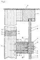
- Fig. 2 details of the static connection of the fire panels 1 using the support 7, the support bracket 8, the plate 9 and further, hereinafter described in more detail parts are shown.
- the support 7 consists of a core 10 made of hardwood, which is covered on all sides with fire protection plates 11, preferably based on calcium silicate.
- the fire protection panels 11 in turn are mainly for aesthetic reasons their outer sides provided with a wooden panel 12.
- the cross section of the support 7 is square or rectangular, but can be realized in basically the same construction and a round wooden support.
- the cross section of the horizontal support bracket 8 corresponds in principle to the cross section of the support 7.
- the support bracket 8 is composed of a core 10 made of hardwood, this core 10 surrounding fire protection panels 11 and finally an optical wood trim 12 together.
- the cross section of the support bracket 8 is square in the embodiment.
- the support bracket 8 is screwed by long screws 13, which emanate from the end face 14 of the support bracket 8, with the core 10 of the support 7.
- FIG. 3 shows a section through the support bracket 8 with the central core 10, the fire protection panels 11 and the wood panel 12. Also shown in dashed lines on the front side 14 of the support bracket 8 attached spacer 15.
- the spacer 15 is in Fig. 2nd shown in section and consists of layer-glued wood, which is preferably impregnated fire-resistant.
- FIG. 4 in which the spacer 15 is shown by itself, shows the cross-shaped configuration of the spacer 15 with a total of four arms 16 a, 16 b, 16 c, 16 d.
- the width and height of the spacer 15 corresponds to the width and height of the support bracket 8, at the end face 14, the spacer 15 is arranged.
- the four arms 16a, 16b, 16c, 16d of the spacer 15 start from a common core 17. In the region of the core 17, the spacer 15 is designed in such a way that the transition from one arm 16 a to the next arm 16 b is designed in the manner of a rounding 18.
- a total of eight flat and flat contact surfaces 19 for the fire protection windows 1 of the glazing are formed on the spacer 15.
- Fig. 5 it is shown how the four total coincident on the spacer 15 fire protection disks 1 abut in their corner region of the contact surfaces 19 of the spacer 15. It is important here that the corners of the fire protection panels 1 are provided with chamfers 20.
- the chamfers 20 are at an angle of 45 ° with respect to the relevant As a result of the chamfers 20 there is no corner contact between the sensitive fire protection glass 1 and the spacer 15. Rather, the fire panels are 1 exclusively with their straight edges 21 on the also just designed contact surfaces 19, so that a planar and non-linear or punctiform support of the sensitive fire protection panels 1 results.
- the plate 9 by means of the screw 23, the head is supported on the outside of the plate 9, bolted to the core 10 of the support bracket 8.
- the screw 23 is through a bore 24 in the middle, d. H. in the core 17 of the spacer 15 passed.
- the plate 9 is provided on its side facing the glazing 25 with recesses 26 for partially receiving the spacer 15. Accordingly, the recesses 26 of the existing wooden plate 9 are formed with a slight oversize as well as the cross-shaped contour of the spacer 15th
Abstract
Description
Die Erfindung betrifft eine Brandschutzverglasung aus mehreren, in einer gemeinsamen Ebene angeordneten Brandschutzscheiben, deren benachbarte Ränder unter Ausbildung einer Trennfuge im Abstand voneinander liegen und die von mindestens einer Stützegehalten sind, die im Abstand zu der Verglasung freistehend im Raum angeordnet und an den raumbegrenzenden Flächen befestigt ist, wobei die Stütze mit Tragkonsolen versehen ist, an denen die Brandschutzscheiben befestigt sind.The invention relates to a fire-resistant glazing of several, arranged in a common plane fire protection windows, the adjacent edges are to form a parting line at a distance from each other and are of at least one support, which is arranged at a distance from the glazing in the room and fixed to the space-limiting surfaces is, wherein the support is provided with support brackets to which the fire panels are attached.
Eine solche Brandschutzverglasung ist aus der EP-B1 0 658 677 bekannt. Ein wesentliches statisches Element dieser Brandschutzverglasungen ist eine Stützkonstruktion aus einer mit Abstand zu den Brandschutzscheiben frei im Raum angeordneten Metallstütze, die mit ihren Enden an den jeweiligen raumbegrenzenden Flächen befestigt ist. Bei derartigen Brandschutzverglasungen ist die sich außerhalb der Verglasungsebene freistehend im Raum befindliche Stützkonstruktion von Vorteil. Deren Metatistützen sind im Brandfall einer allseitigen Hitzewirkung ausgesetzt, so daß sie sich im wesentlichen gleichmäßig und ohne größere Verspannungen ausdehnen können. Infolge dieses weitgehend spannungsarmen Verhaltens lassen sich auch temperaturbedingte Spannungen auf die Brandschutzverglasung gering halten, so daß diese auch bei länger andauernder Einwirkung von Feuer und Hitze keine stärkeren Wölbungenzeigt.Such fire-resistant glazing is known from EP-B1 0 658 677. An essential static element of this fire-resistant glazing is a support structure made of a metal support which is arranged freely in the room at a distance from the fire-protection panes and which is fastened by its ends to the respective space-limiting surfaces. In such fire-resistant glazing, which is located outside the glazing level freestanding in the support structure is advantageous. Their metatarsals are exposed in case of fire to an all-round heat effect, so that they can expand substantially uniformly and without major tension. As a result of this largely stress-free behavior, temperature-induced stresses on the fire-resistant glazing can be kept low, so that even with prolonged exposure to fire and heat it shows no more pronounced bulges.
Bei der Brandsch utzverglasung nach der EP-B1 0 658 677 sind die Brandschutzscheiben mit den Tragkonsolen jeweils mittels zweier Stützplatten verbunden. Diese spannen die jeweilige Brandschutzscheibe zwischen sich ein, wozu sie durch Schrauben miteinander verspannt sind, die Bohrungen in den Brandschutzscheiben durchgreifen. Der Nachteil dieser Konstruktion ist darin zu sehen, daß das Herstellen derartiger Bohrungen im Eckenbereich der Brandschutzscheiben schwierig ist, zumal Brandschutzscheiben mehrlagig mit zwischen Glasschichten angeordneten, einen im Brandfall aufschäumenden Schutzwirkstoff enthaltenden Schichten aufgebaut sind, und die Brandschutzscheiben infolge dieses Aufbaus kritisch auf punktförmige mechanische Belastungen reagieren. Besonders empfindlich sind Brandschutzscheiben im Randbereich und hier wiederum im Eckenbereich, weshalb es anzustreben ist, in der Nähe dieser kritischen Zonen auf eine nachträgliche mechanische Bearbeitung der Brandschutzscheiben so weit als möglich zu verzichten.In the fire protection glazing according to EP-B1 0 658 677, the fire protection windows with the support brackets are each by means of two support plates connected. These clamp the respective fire protection pane between them, to which they are clamped together by screws which pass through the holes in the fire protection windows. The disadvantage of this construction is the fact that the production of such holes in the corner region of the fire protection is difficult, especially since fire panels are multi-layered arranged between glass layers, built up in the event of fire protective active layers containing layers, and the fire protection due to this structure critical to punctiform mechanical loads react. Particularly sensitive are fire protection windows in the edge area and here again in the corner area, which is why it should be strived to dispense as far as possible in the vicinity of these critical zones on a subsequent mechanical processing of the fire protection windows.
Aus der EP-A 0 712 971 ist eine Fassadenverkleidung unter anderem für Brandschutzverglasungen bekannt, bei der die Platten mit der Gebäudestruktur über Plattenhalter verbunden sind. Diese Plattenhalter sind an den waagerechten Rändern der Fassadenplatten angeordnet und bestehen aus zwei Klemmplatten, die durch Spannmittel in der Form von Schrauben miteinander verspannt sind. Diese Schrauben liegen in den Trennfugen zwischen den Fassadenplatten und spannen die Fassadenplatten unter Zwischenfügen von elastischen Dichtungen zwischen sich ein. Die innere Klemmplatte ist über einen Gewindebolzen mit der Gebäudestruktur verbunden. Bei dieser Konstruktion werden zwar Bohrungen oder Durchbrüche in den Fassadenplatten vermieden; die Fassadenplatten werden jedoch im Randbereich mit einer gewissen Klemmkraft eingespannt, die insbesondere im Brandfall zu einer erhöhten mechanischen Belastung führt, die gerade im Randbereich von Brandschutzscheiben ungünstig ist und zu vorzeitigen Zerstörungen führen kann.From EP-A 0 712 971 a facade cladding, inter alia, for fire-resistant glazings is known in which the plates are connected to the building structure via plate holder. These plate holders are arranged on the horizontal edges of the facade panels and consist of two clamping plates, which are clamped together by clamping means in the form of screws. These screws are located in the joints between the facade panels and clamp the facade panels with the interposition of elastic seals between them. The inner clamping plate is connected to the building structure via a threaded bolt. In this construction, although holes or breakthroughs are avoided in the facade panels; However, the facade panels are clamped in the edge region with a certain clamping force, which leads in particular to fire in an increased mechanical load, which is unfavorable especially in the edge of fire protection windows and can lead to premature destruction.
Auch bei der Konstruktion nach der EP-A 0 384 418, die eine brandsichere Halterung für Brandschutzscheiben zeigt, werden die Scheiben im Randbereich zwischen einer Halteleiste und einem Halteprofil unter Zwischenfügen von Dichtelementen mittels Verschraubungen eingespannt. Die Verschraubungen sind über ein Tragprofil mit dem Gebäude verbunden. Bei dieser bekannten Konstruktion werden keine punktförmigen Plattenhalter verwendet, sondern ganzflächig an den Rändern der Scheiben angreifende Profile. Beide der voranstehend beschriebenen Konstruktionen unterscheiden sich von der eingangs abgewandelten EP-B1 0 658 677 dadurch, daß die Brandschutzscheiben unmittelbar mit dem Gebäude verbunden sind und keine freistehend im Raum angeordnete Stützkonstruktion verwenden, deren Stützen im Brandfall allseitig der Hitzeeinwirkung ausgesetzt sind.Also in the construction according to EP-A 0 384 418, which shows a fireproof holder for fire protection panels, the discs are clamped in the edge region between a retaining strip and a retaining profile with the interposition of sealing elements by means of screwing. The glands are connected to the building via a supporting profile. In this known construction, no punctiform plate holders are used, but over the entire surface at the edges of the discs attacking profiles. Both of the above-described constructions differ from the initially modified EP-B1 0 658 677 in that the fire panels are directly connected to the building and no freestanding space arranged support structure use, the supports are exposed in all cases of heat in the event of fire.
Der Erfindung liegt die Aufgabe zugrunde, eine sich auch im Brandfall spannungsarm verhaltende Brandschutzverglasung zu schaffen, bei der kritische mechanische Belastungen im problematischen Rand- und Eckenbereich der Brandschutzscheiben vermieden werden.The invention has for its object to provide a low-voltage even in case of fire behaving fire-resistant glazing, are avoided in the critical mechanical stresses in problematic edge and corner area of the fire protection.
Die Lösung dieser Aufgabenstellung durch die Erfindung ist dadurch gekennzeichnet, daß jeweils eine Ecke von vier aneinander grenzenden Brandschutzscheiben mittels eines Distanzstückes in Gestalt eines vierarmigen Kreuzes an jeder Tragkonsolegehalten sind, wobei sich die Arme des Distanzstückes in den Trennfuge befinden, die zwei jeweils oberhalb des Distanzstückes angeordneten Brändschutzscheiben auf dem Distanzstück aufstehen und alle vier Brandschutzscheiben durch eine Platte seitlich gehalten sind, die auf der der Stütze abgewandten Seite der Verglasung einen Teil des Randes der Brandschutzscheiben überdeckt und mittels einer Schraube mit der Tragkonsole verbunden ist.The solution of this problem by the invention is characterized in that in each case a corner of four adjacent fire protection discs are held by means of a spacer in the form of a four-armed cross on each support bracket, wherein the arms of the spacer are in the parting line, the two each above the spacer arranged fire protection disks stand up on the spacer and all four fire protection panels are held laterally by a plate which covers on the side facing away from the support of the glazing part of the edge of the fire panels and is connected by a screw to the support bracket.
Mit der erfindungsgemäßen Brandschutzverglasung, die ohne Bohrungen in dem besonders kritischen Rand- und Eckenbereich der beteiligten Brandschutzscheiben auskommt, werden mechanische Spannungsspitzen infolge einer punkt- oder linienförmigen Abführung des beträchtlichen Gewichtes der mehrlagigen Brandschutzscheiben vermieden. Die Brandschutzscheiben stehen mit ihrer Stirnfläche großflächig auf dem Distanzstück auf, welches mit der jeweiligen Tragkonsole der Stütze verbunden ist, ohne eine Klemm- oder Einspannkraft auf die Brandschutzscheiben auszuüben. Durch das großflächige Aufstehen ist die mechanische Belastung des empfindlichen Randes der Brandschutzscheiben deutlich geringer als beim Stand der Technik. Die seitlich auf die Brandschutzverglasung einwirkenden Kräfte werden von der Tragkonsole bzw. der Platte ausgenommen. Da diese Platte einen Teil des Randes der Brandschutzscheiben überdeckt, werden die seitlichen Kräfte von der Platte über die Tragkonsole auf die Stütze abgeführt. Gleichzeitig deckt die Platte das Distanzstück ab, so daß dieses bei einer frontalen Betrachtung der Brandschutzscheibe unsichtbar ist.With the fire-resistant glazing according to the invention, which does not require drilling in the particularly critical edge and corner areas of the fire protection panels involved, mechanical stress peaks due to a point or linear discharge of the considerable weight of the multilayer fire protection windows are avoided. The fire protection discs are with their end face over a large area on the spacer, which is connected to the respective support bracket of the support, without exerting a clamping or clamping force on the fire protection windows. Due to the large-area standing up, the mechanical load on the sensitive edge of the fire-resistant windows is significantly lower than in the prior art. The lateral forces acting on the fire-resistant glazing are excluded from the support bracket or the plate. Since this plate is part of the edge of the Covered fire panels, the lateral forces are removed from the plate via the support bracket on the support. At the same time the plate covers the spacer, so that this is invisible in a frontal view of the fire panel.
Bei einer bevorzugten Ausführungsform der Erfindung durchdringt die Schraube eine zentrale Bohrung des Distanzstückes.In a preferred embodiment of the invention, the screw penetrates a central bore of the spacer.
Gemäß einem weiteren Merkmal der Erfindung ist der Übergang zwischen den Armen des Distanzstückes gerundet. Durch eine solche Rundung läßt sich die Festigkeit des Distanzstückes in jenen Bereichen verbessern, in denen die Beanspruchung infolge der Gewichtslast der auf dem jeweiligen Arm sich aufstützenden Brandschutzscheibe besonders groß ist.According to a further feature of the invention, the transition between the arms of the spacer is rounded. By such a rounding, the strength of the spacer can be improved in those areas in which the stress due to the weight load of the respective arm supporting fire protection screen is particularly large.
Hierbei ist es von Vorteil, wenn erfindungsgemäß die Ecken der Brandschutzscheiben, vorzugsweise unter einem Winkel von 45° angeschrägt sind. Auf diese Weise ist sichergestellt, daß sich die Brandschutzscheibe ausschließlich flächig auf einem der Arme des Distanzstückes abstützt, ohne daß es zu mechanischen Belastungen im unmittelbaren Eckenbereich der Brandschutzscheibe kommt.It is advantageous if, according to the invention, the corners of the fire protection windows are bevelled, preferably at an angle of 45 °. In this way, it is ensured that the fire protection plate is supported exclusively flat on one of the arms of the spacer, without causing mechanical stresses in the immediate corner region of the fire protection pane.
Zur eindeutigen Festlegung und Sicherung der Lage und Ausrichtung der Platte in Bezug auf die Tragkonsole wird weiterhin mit der Erfindung vorgeschlagen, daß die Platte an ihren der Verglasung zugewandten Seite mit Vertiefungen zur teilweisen Aufnahme des Distanzstückes versehen ist. Durch diese Ausgestaltung lassen sich Spalte zwischen Distanzstück einerseits und Platte andererseits vermeiden, wodurch der Abstand zwischen der Stirnseite der Tragkonsole und der Platte vollständig von dem Distanzstück überbrückt wird und damit eine entsprechend große Fläche des Distanzstückes zur Verfügung steht, um darauf die Brandschutzscheiben mit ihrer Stimfläche abzusetzen.For unambiguous determination and securing the position and orientation of the plate with respect to the support bracket is further proposed with the invention that the plate is provided at its side facing the glazing with recesses for partially receiving the spacer. By this configuration, gaps between spacers on the one hand and plate on the other hand can be avoided, whereby the distance between the end face of the support bracket and the plate is completely bridged by the spacer and thus a correspondingly large area of the spacer is available to it the fire panels with their end face discontinued.
Die erfindungsgemäße Konstruktion einer Brandschutzverglasung ist wegen ihres einfachen Aufbaus und ihrer spannungsvermeidenden Halterung der Brandschutzscheiben besonders geeignet, ganz oder teilweise aus Holz hergestellt zu werden. Mit der Erfindung wird demgemäß vorgeschlagen, die Tragkonsole und/oder die Stütze aus einem Holzkern herzustellen, der allseitig von Brandschutzplatten umgeben ist. In beiden Fällen können aus optischen Gründen die Außenseiten der Brandschutzplatten mit einer Holzverkleidung versehen sein, so daß für den Betrachter der Eindruck einer allein aus Holz bestehenden Stützkonstruktion entsteht. Bei einer bevorzugten Ausgestaltung der Erfindung besteht auch das Distanzstück aus Holz, vorzugsweise aus Schicht verleimtem Holz. Zur Verbesserung der Resistenz gegenüber Feuer kann das Holz in geeigneter Weise vorbehandelt sein, etwa durch eine den Entflammpunkt heraufsetzenden Imprägnierung.The construction of a fire-resistant glazing according to the invention is particularly suitable because of its simple structure and its voltage-dissipating mounting of the fire protection glass to be made entirely or partially of wood. The invention accordingly proposes that Support bracket and / or the support made of a wood core, which is surrounded on all sides by fire protection plates. In both cases, the outer sides of the fire protection panels may be provided with a wooden cladding for visual reasons, so that the viewer the impression of an existing solely wooden support structure is created. In a preferred embodiment of the invention, the spacer is made of wood, preferably made of layer of glued wood. To improve the resistance to fire, the wood may be pretreated in a suitable manner, for example by an impregnation increasing the flash point.
Weitere Einzelheiten und Vorteile des Gegenstandes der Erfindung werden nachfolgend anhand der Zeichnung erläutert. Darin zeigen:
- Fig. 1
- in Frontalansicht eine aus insgesamt neun Brandschutzscheiben zusammengesetzte Brandschutzverglasung;
- Fig. 2
- einen stark verkürzt dargestellten Teilschnitt durch die Brandschutzverglasung entsprechend der in Fig. 1 eingezeichneten Schnittebene II-II;
- Fig. 3
- einen Schnitt durch eine Tragkonsole der Brandschutzverglasung gemäß der in Fig. 2 eingezeichneten Schnittebene III-III;
- Fig. 4
- in Ansichtsdarstellung ein an der Tragkonsole nach Fig. 3 befestigtes Distanzstück in Gestalt eine vierarmigen Kreuzes;
- Fig. 5
- die Anordnung von insgesamt vier Brandschutzscheiben an dem Distanzstück;
- Fig. 6a
- eine Seitenansicht einer Platte, die den Abschluß der Tragkonsole bildet, und
- Fig. 6b
- eine Ansicht der Platte gemäß der in Fig. 6a eingezeichneten Ansichtsebene A.
- Fig. 1
- in frontal view, a fire-resistant glazing composed of a total of nine fire-resistant panes;
- Fig. 2
- a section of the fire protection glazing shown in greatly shortened form according to the section plane II-II shown in FIG. 1;
- Fig. 3
- a section through a support bracket of fire-resistant glazing according to the drawn in Figure 2 sectional plane III-III.
- Fig. 4
- in view of a mounted on the support bracket of Figure 3 spacer in the shape of a four-armed cross.
- Fig. 5
- the arrangement of a total of four fire panels on the spacer;
- Fig. 6a
- a side view of a plate, which forms the end of the support bracket, and
- Fig. 6b
- a view of the plate according to the drawn in Fig. 6a view plane A.
Die in Fig. 1 dargestellte Brandschutzverglasung dient der lichtdurchlässigen Unterteilung zweier aneinandergrenzender Räume und besteht aus insgesamt neun feststehenden Brandschutzscheiben 1. Bestandteil der Brandschutzverglasung können auch bewegliche und als Türflügel ausgebildete Brandschutzscheiben sein. Eine solche Brandschutzverglasung unter Einbeziehung einer doppelflügeligen Tür ist z. B. in der EP 0 658 677 B1 dargestellt.The fire-resistant glazing shown in Fig. 1 is the translucent subdivision of two adjoining rooms and consists of a total of nine fixed
Um die Brandschutzverglasung zu fixieren, ist diese zunächst entlang der raumbegrenzenden Flächen, d. h. der Wände 2, der Decke 3 sowie dem Boden 4 als im wesentlichen herkömmlich ausgeführte, wandseitige Rahmenkonstruktion 6 ausgeführt. Allein diese wandseitige Rahmenkonstruktion 6 würde der Brandschutzverglasung jedoch noch keine ausreichende Stabilität gegenüber seitlichen Kräften verleihen. Vielmehr sind zusätzlich zwei Stützkonstruktionen unter Verwendung jeweils einer Stütze 7 vorgesehen, wobei jede Stütze 7 mit ihrem unteren Ende am Boden 4 und mit ihrem oberen Ende an der Decke 3 des Raumes befestigt ist. Die beiden Stützen 7 befinden sich bei der Ausführungsform nach Fig. 1 hinter der eigentlichen Ebene der Verglasung frei im Raum, weshalb die Stützen 7 gestrichelt dargestellt sind.To fix the fire-resistant glazing, this is initially along the space-limiting surfaces, d. H. the
Von den vertikalen Stützen 7 aus erstrecken sich horizontale Tragkonsolen 8 zu jenen Punkten der Verglasung, an denen die Ecken von insgesamt vier einander benachbarten Brandschutzscheiben 1 aufeinandertreffen. In Fig. 1 ist von jeder Tragkonsole 8 lediglich eine Platte 9 zu erkennen, welche die Tragkonsole 8 an deren Stirnseite abdeckt. Die Ecken der beteiligten Brandschutzscheiben 1 sind hierbei zwischen dieser Platte 9 und der Stirnseite 14 der Tragkonsole 8 eingespannt und auf diese Weise in seitlicher Richtung gesichert.From the
In Fig. 2 sind Einzelheiten der statischen Anbindung der Brandschutzscheiben 1 unter Verwendung der Stütze 7, der Tragkonsole 8, der Platte 9 sowie weiterer, nachfolgend noch näher beschriebener Teile dargestellt.In Fig. 2 details of the static connection of the
Die Stütze 7 besteht aus einem Kern 10 aus Hartholz, der allseitig mit Brandschutzplatten 11, vorzugsweise auf Basis von Kalzium-Silikat, verkleidet ist. Die Brandschutzplatten 11 wiederum sind aus vor allem ästhetischen Gründen auf ihren Außenseiten mit einer Holzverkleidung 12 versehen. Vorzugsweise ist der Querschnitt der Stütze 7 quadratisch oder rechteckig, jedoch läßt sich in grundsätzlich gleichem Aufbau auch eine runde Holzstütze verwirklichen.The
Der Querschnitt der horizontalen Tragkonsole 8 entspricht im Prinzip dem Querschnitt der Stütze 7. Auch die Tragkonsole 8 setzt sich aus einem Kern 10 aus Hartholz, diesen Kern 10 umgebenden Brandschutzplatten 11 sowie schließlich einer optischen Holzverkleidung 12 zusammen. Auch der Querschnitt der Tragkonsole 8 ist beim Ausführungsbeispiel quadratisch. Die Tragkonsole 8 ist über lange Schrauben 13, die von der Stirnseite 14 der Tragkonsole 8 ausgehen, mit dem Kern 10 der Stütze 7 verschraubt.The cross section of the
Fig. 3 zeigt einen Schnitt durch die Tragkonsole 8 mit dem zentralen Kern 10, den Brandschutzplatten 11 sowie der Holzverkleidung 12. Ferner dargestellt ist in gestrichelten Linien ein auf die Stirnseite 14 der Tragkonsole 8 aufgesetztes Distanzstück 15. Das Distanzstück 15 ist in Fig. 2 im Schnitt dargestellt und besteht aus schichtverleimtem Holz, welches vorzugsweise feuerwiderstandsfähig imprägniert ist.3 shows a section through the
Insbesondere Fig. 4, in der das Distanzstück 15 für sich alleine dargestellt ist, zeigt die kreuzförmige Gestaltung des Distanzstücks 15 mit insgesamt vier Armen 16a, 16b, 16c, 16d. Die Breite und Höhe des Distanzstücks 15 entspricht der Breite und Höhe der Tragkonsole 8, an deren Stirnseite 14 das Distanzstück 15 angeordnet ist. Die vier Arme 16a, 16b, 16c,16d des Distanzstücks 15 gehen von einem gemeinsamen Kern 17 aus. Im Bereich des Kerns 17 ist das Distanzstück 15 in der Weise gestaltet, daß der Übergang von einem Arm 16a zum nächstfolgenden Arm 16b nach Art einer Rundung 18 gestaltet ist.In particular, Fig. 4, in which the
Infolge der Arme 16a, 16b, 16c, 16d sind an dem Distanzstück 15 insgesamt acht flache und ebene Anlageflächen 19 für die Brandschutzscheiben 1 der Verglasung ausgebildet. In Fig. 5 ist dargestellt, wie die insgesamt vier an dem Distanzstück 15 zusammentreffenden Brandschutzscheiben 1 in ihrem Eckenbereich an den Anlageflächen 19 des Distanzstücks 15 anliegen. Wichtig ist hierbei, daß die Ecken der Brandschutzscheiben 1 mit Anschrägungen 20 versehen sind. Die Anschrägungen 20 liegen unter einem Winkel von 45° bezüglich der betreffenden Ränder 21 der Brandschutzscheibe 1. Infolge der Anschrägungen 20 kommt es zu keinem Eckenkontakt zwischen den empfindlichen Brandschutzscheiben 1 und dem Distanzstück 15. Vielmehr liegen die Brandschutzscheiben 1 ausschließlich mit ihren gerade verlaufenden Rändern 21 auf den ebenfalls gerade gestalteten Anlageflächen 19 auf, so daß sich eine flächige und nicht linienförmige oder punktförmige Abstützung der empfindlichen Brandschutzscheiben 1 ergibt.As a result of the
Die Dicke der vier Arme16a, 16b, 16c und 16d des Distanzstücks 15 bedingt die Breite b der Trennfuge 22 zwischen benachbarten Brandschutzscheiben 1. Diese Trennfuge 22 wird nach erfolgter Montage der Brandschutzverglasung mit einer Silikonfüllung verschlossen.The thickness of the four Arme16a, 16b, 16c and 16d of the
Während die horizontalen und in geringerem Umfang auch die vertikalen Kräfte in der Verglasungsebene über das Distanzstück 15 und die Tragkonsole 8 auf die Stütze 7 abgeführt werden, werden die seitlichen Kräfte einerseits von der Stirnseite 14 der Tragkonsole 8, und andererseits von der Platte 9 aufgenommen. Hierzu ist die Platte 9 mittels der Schraube 23, deren Kopf sich auf der Außenseite der Platte 9 abstützt, mit dem Kern 10 der Tragkonsole 8 verschraubt. Die Schraube 23 ist durch eine Bohrung 24 in der Mitte, d. h. im Kern 17 des Distanzstücks 15 hindurchgeführt.While the horizontal and to a lesser extent also the vertical forces in the glazing plane are dissipated via the
In den Fign. 6a und 6b ist dargestellt, daß die Platte 9 an ihrer der Verglasung zugewandten Seite 25 mit Vertiefungen 26 zur teilweisen Aufnahme des Distanzstücks 15 versehen ist. Entsprechend sind die Vertiefungen 26 der aus Holz bestehenden Platte 9 mit geringem Übermaß ebenso geformt, wie die kreuzförmige Kontur des Distanzstücks 15.In the Fign. 6a and 6b it is shown that the
- 11
- BrandschutzscheibeFireproof panel
- 22
- Wandwall
- 33
- Deckeblanket
- 44
- Bodenground
- 66
- Rahmenkonstruktionframe construction
- 77
- Stützesupport
- 88th
- Tragkonsolesupport bracket
- 99
- Platteplate
- 1010
- Kerncore
- 1111
- BrandschutzplatteFire protection panel
- 1212
- Holzverkleidungwood paneling
- 1313
- Schraubescrew
- 1414
- Stirnseitefront
- 1515
- Distanzstückspacer
- 16a16a
- Armpoor
- 16b16b
- Armpoor
- 16c16c
- Armpoor
- 16d16d
- Armpoor
- 1717
- Kerncore
- 1818
- Rundungcurve
- 1919
- Anlageflächecontact surface
- 2020
- Anschrägungbevel
- 2121
- Randedge
- 2222
- Trennfugeparting line
- 2323
- Schraubescrew
- 2424
- Bohrungdrilling
- 2525
- Seitepage
- 2626
- Vertiefungdeepening
Claims (8)
- Fire protective glazing comprising a plurality of fire protective panes (1) arranged in a common plane, adjacent edges (21) of which are disposed at a distance from one another and form a dividing gap (22) and which are supported by at least one column (7), which is arranged freestanding in the space at a distance from the glazing and is secured to the surfaces (3, 4) defining the space, the column (7) being provided with support brackets (8), to which the fire protective panes (1) are secured, characterised in that a respective corner of four adjoining fire protective panes (1) are supported on each support bracket (8) by means of a spacer (15) in the shape of a four-armed cross, the arms (16a, 16b, 16c, 16d) of the spacer (15) being situated in the dividing gaps (22), the two fire protective panes disposed above the spacer (15) resting on the spacer (15) and all four fire protective panes (1) being laterally held by a plate (9), which overlaps a portion of the edge (21) of the fire protective panes (1) on the side of the glazing remote from the column (7) and is connected to the support bracket (8) by means of a screw (23).
- Fire protective glazing as claimed in Claim 1, characterised in that the screw (23) passes through a central bore (24) in the spacer (15).
- Fire protective glazing as claimed in Claim 1 or 2, characterised in that the transition between the arms (16a, 16b, 16c, 16d) of the spacer (15) is rounded.
- Fire protective glazing as claimed in Claim 3, characterised in that the corners of the fire protective panes (1) are bevelled, preferably at 45°.
- Fire protective glazing as claimed in one of Claims 1 to 4, characterised in that the plate (9) is provided on its side (25) directed towards the glazing with recesses (26) for partially receiving the spacer (15).
- Fire protective glazing as claimed in at least one of Claims 1 to 5, characterised in that the support bracket (8) and/or the column (7) comprise a wood core (10), which is surrounded on all sides by fire protective plates (11).
- Fire protective glazing as claimed in Claim 6, characterised in that the outer surfaces of the fire protective plates (11) are provided with a wood facing (12).
- Fire protective glazing as claimed in at least one of Claims 1 to 7, characterised in that the spacer (15) consists of wood, preferably of plywood.
Priority Applications (3)
| Application Number | Priority Date | Filing Date | Title |
|---|---|---|---|
| AT01100432T ATE329123T1 (en) | 2001-01-08 | 2001-01-08 | FIRE PROTECTION GLAZING |
| EP01100432A EP1221528B1 (en) | 2001-01-08 | 2001-01-08 | Fire-resistant glazing |
| DE50110032T DE50110032D1 (en) | 2001-01-08 | 2001-01-08 | Fire-resistant glazing |
Applications Claiming Priority (1)
| Application Number | Priority Date | Filing Date | Title |
|---|---|---|---|
| EP01100432A EP1221528B1 (en) | 2001-01-08 | 2001-01-08 | Fire-resistant glazing |
Publications (2)
| Publication Number | Publication Date |
|---|---|
| EP1221528A1 EP1221528A1 (en) | 2002-07-10 |
| EP1221528B1 true EP1221528B1 (en) | 2006-06-07 |
Family
ID=8176160
Family Applications (1)
| Application Number | Title | Priority Date | Filing Date |
|---|---|---|---|
| EP01100432A Expired - Lifetime EP1221528B1 (en) | 2001-01-08 | 2001-01-08 | Fire-resistant glazing |
Country Status (3)
| Country | Link |
|---|---|
| EP (1) | EP1221528B1 (en) |
| AT (1) | ATE329123T1 (en) |
| DE (1) | DE50110032D1 (en) |
Families Citing this family (2)
| Publication number | Priority date | Publication date | Assignee | Title |
|---|---|---|---|---|
| DE102006010699A1 (en) * | 2006-03-08 | 2007-09-20 | Schott Ag | Fire-resistant glazing |
| AT512245B1 (en) * | 2011-05-09 | 2016-05-15 | IPM Schober Fenster GmbH | Fire window |
Family Cites Families (4)
| Publication number | Priority date | Publication date | Assignee | Title |
|---|---|---|---|---|
| DE3302044C3 (en) * | 1983-01-22 | 1993-11-18 | August Eich | Fire protection partition |
| DE3905727A1 (en) * | 1989-02-24 | 1990-08-30 | Eberspaecher J | FIRE-RESISTANT MOUNTING AT LEAST ONE DISC |
| ATE191765T1 (en) * | 1994-11-16 | 2000-04-15 | Vetrotech Saint Gobain Int Ag | DEVICE FOR MOUNTING AND FASTENING FACADE PANELS |
| AT403824B (en) * | 1995-06-16 | 1998-05-25 | Pagitz Elisabeth Mag | FIRE PROTECTION FACADE |
-
2001
- 2001-01-08 DE DE50110032T patent/DE50110032D1/en not_active Expired - Lifetime
- 2001-01-08 EP EP01100432A patent/EP1221528B1/en not_active Expired - Lifetime
- 2001-01-08 AT AT01100432T patent/ATE329123T1/en active
Also Published As
| Publication number | Publication date |
|---|---|
| EP1221528A1 (en) | 2002-07-10 |
| DE50110032D1 (en) | 2006-07-20 |
| ATE329123T1 (en) | 2006-06-15 |
Similar Documents
| Publication | Publication Date | Title |
|---|---|---|
| DE3541730A1 (en) | FAIRING FOR EXTERNAL SURFACES OF BUILDINGS | |
| DE3908983A1 (en) | GLASS COMPONENT FOR A WHOLE GLASS FACADE | |
| DE19733154B4 (en) | Door or window arrangement with frameless door or window sash arrangement with insulating glazing | |
| DE102009023883B4 (en) | facade element | |
| WO2010097179A1 (en) | Fire protection glazing | |
| WO2010063297A1 (en) | Mounting system for insulating glass panes | |
| DE3812223A1 (en) | Facade having a load-bearing structure, comprising post profiles and crossmember profiles, and a fireproof glazing | |
| EP2226458A2 (en) | Fire protection glazing | |
| EP1194673A1 (en) | Fire-inhibiting flat element comprising at least two transparent fire-resisting glass plates | |
| EP2405093B1 (en) | Modular flame retardant glazing | |
| EP1221528B1 (en) | Fire-resistant glazing | |
| EP0686735A1 (en) | Building façade | |
| EP0411442A2 (en) | Device to support hanging stone plates for façade covering | |
| DE3808981C2 (en) | ||
| DE10312244B4 (en) | Facade cladding made of insulating glass panes | |
| EP0712971B1 (en) | Arrangement for mounting and fastening of facade plates | |
| EP3085873A2 (en) | Effect panel | |
| DE8019472U1 (en) | WINDOW | |
| EP3473796A1 (en) | Fixed glazing system for fixing a glass retaining strip with definable contact pressure | |
| DE202004001795U1 (en) | glazing | |
| EP3530860A1 (en) | Insulation glass element for a glass façade and glass façade | |
| EP3323954B1 (en) | Post and crossmember structure | |
| EP0357994A2 (en) | Frame construction in mullion-transom-art, in particular for façades, roofs or the like | |
| DE4123604A1 (en) | Facade panel mounting system - comprises glass panel bonded to profiled frame along long edges and having countersunk holes for screw fastening to frame | |
| DE19854203A1 (en) | Building facade post and beam system uses armed support element grooved into post and beam and covered by side strips applying pressure to inserted glazing seals |
Legal Events
| Date | Code | Title | Description |
|---|---|---|---|
| PUAI | Public reference made under article 153(3) epc to a published international application that has entered the european phase |
Free format text: ORIGINAL CODE: 0009012 |
|
| AK | Designated contracting states |
Kind code of ref document: A1 Designated state(s): AT BE CH CY DE DK ES FI FR GB GR IE IT LI LU MC NL PT SE TR |
|
| AX | Request for extension of the european patent |
Free format text: AL;LT;LV;MK;RO;SI |
|
| 17P | Request for examination filed |
Effective date: 20021211 |
|
| AKX | Designation fees paid |
Designated state(s): AT BE CH CY DE DK ES FI FR GB GR IE IT LI LU MC NL PT SE TR |
|
| 17Q | First examination report despatched |
Effective date: 20050316 |
|
| GRAP | Despatch of communication of intention to grant a patent |
Free format text: ORIGINAL CODE: EPIDOSNIGR1 |
|
| GRAS | Grant fee paid |
Free format text: ORIGINAL CODE: EPIDOSNIGR3 |
|
| GRAA | (expected) grant |
Free format text: ORIGINAL CODE: 0009210 |
|
| AK | Designated contracting states |
Kind code of ref document: B1 Designated state(s): AT BE CH CY DE DK ES FI FR GB GR IE IT LI LU MC NL PT SE TR |
|
| PG25 | Lapsed in a contracting state [announced via postgrant information from national office to epo] |
Ref country code: IT Free format text: LAPSE BECAUSE OF FAILURE TO SUBMIT A TRANSLATION OF THE DESCRIPTION OR TO PAY THE FEE WITHIN THE PRE;WARNING: LAPSES OF ITALIAN PATENTS WITH EFFECTIVE DATE BEFORE 2007 MAY HAVE OCCURRED AT ANY TIME BEFORE 2007. THE CORRECT EFFECTIVE DATE MAY BE DIFFERENT FROM THE ONE RECORDED.SCRIBED TIME-LIMIT Effective date: 20060607 Ref country code: IE Free format text: LAPSE BECAUSE OF FAILURE TO SUBMIT A TRANSLATION OF THE DESCRIPTION OR TO PAY THE FEE WITHIN THE PRESCRIBED TIME-LIMIT Effective date: 20060607 Ref country code: FI Free format text: LAPSE BECAUSE OF FAILURE TO SUBMIT A TRANSLATION OF THE DESCRIPTION OR TO PAY THE FEE WITHIN THE PRESCRIBED TIME-LIMIT Effective date: 20060607 |
|
| REG | Reference to a national code |
Ref country code: GB Ref legal event code: FG4D Free format text: NOT ENGLISH |
|
| REG | Reference to a national code |
Ref country code: CH Ref legal event code: EP |
|
| GBT | Gb: translation of ep patent filed (gb section 77(6)(a)/1977) |
Effective date: 20060607 |
|
| REG | Reference to a national code |
Ref country code: CH Ref legal event code: NV Representative=s name: E. BLUM & CO. PATENTANWAELTE |
|
| REG | Reference to a national code |
Ref country code: IE Ref legal event code: FG4D Free format text: LANGUAGE OF EP DOCUMENT: GERMAN |
|
| REF | Corresponds to: |
Ref document number: 50110032 Country of ref document: DE Date of ref document: 20060720 Kind code of ref document: P |
|
| PG25 | Lapsed in a contracting state [announced via postgrant information from national office to epo] |
Ref country code: DK Free format text: LAPSE BECAUSE OF FAILURE TO SUBMIT A TRANSLATION OF THE DESCRIPTION OR TO PAY THE FEE WITHIN THE PRESCRIBED TIME-LIMIT Effective date: 20060907 Ref country code: SE Free format text: LAPSE BECAUSE OF FAILURE TO SUBMIT A TRANSLATION OF THE DESCRIPTION OR TO PAY THE FEE WITHIN THE PRESCRIBED TIME-LIMIT Effective date: 20060907 |
|
| PG25 | Lapsed in a contracting state [announced via postgrant information from national office to epo] |
Ref country code: ES Free format text: LAPSE BECAUSE OF FAILURE TO SUBMIT A TRANSLATION OF THE DESCRIPTION OR TO PAY THE FEE WITHIN THE PRESCRIBED TIME-LIMIT Effective date: 20060918 |
|
| PG25 | Lapsed in a contracting state [announced via postgrant information from national office to epo] |
Ref country code: PT Free format text: LAPSE BECAUSE OF FAILURE TO SUBMIT A TRANSLATION OF THE DESCRIPTION OR TO PAY THE FEE WITHIN THE PRESCRIBED TIME-LIMIT Effective date: 20061107 |
|
| ET | Fr: translation filed | ||
| PG25 | Lapsed in a contracting state [announced via postgrant information from national office to epo] |
Ref country code: MC Free format text: LAPSE BECAUSE OF NON-PAYMENT OF DUE FEES Effective date: 20070131 |
|
| REG | Reference to a national code |
Ref country code: IE Ref legal event code: FD4D |
|
| PLBE | No opposition filed within time limit |
Free format text: ORIGINAL CODE: 0009261 |
|
| STAA | Information on the status of an ep patent application or granted ep patent |
Free format text: STATUS: NO OPPOSITION FILED WITHIN TIME LIMIT |
|
| 26N | No opposition filed |
Effective date: 20070308 |
|
| REG | Reference to a national code |
Ref country code: CH Ref legal event code: PFA Owner name: HOLZBAU SCHMID GMBH & CO. KG Free format text: HOLZBAU SCHMID GMBH & CO. KG#ZIEGELHAU 1-4#73099 ADELBERG (DE) $ PROMAT GMBH#SCHEIFENKAMP 16#40878 RATINGEN (DE) -TRANSFER TO- HOLZBAU SCHMID GMBH & CO. KG#ZIEGELHAU 1-4#73099 ADELBERG (DE) $ PROMAT GMBH#SCHEIFENKAMP 16#40878 RATINGEN (DE) |
|
| PG25 | Lapsed in a contracting state [announced via postgrant information from national office to epo] |
Ref country code: GR Free format text: LAPSE BECAUSE OF FAILURE TO SUBMIT A TRANSLATION OF THE DESCRIPTION OR TO PAY THE FEE WITHIN THE PRESCRIBED TIME-LIMIT Effective date: 20060908 |
|
| PG25 | Lapsed in a contracting state [announced via postgrant information from national office to epo] |
Ref country code: LU Free format text: LAPSE BECAUSE OF NON-PAYMENT OF DUE FEES Effective date: 20070108 Ref country code: CY Free format text: LAPSE BECAUSE OF FAILURE TO SUBMIT A TRANSLATION OF THE DESCRIPTION OR TO PAY THE FEE WITHIN THE PRESCRIBED TIME-LIMIT Effective date: 20060607 |
|
| PG25 | Lapsed in a contracting state [announced via postgrant information from national office to epo] |
Ref country code: TR Free format text: LAPSE BECAUSE OF FAILURE TO SUBMIT A TRANSLATION OF THE DESCRIPTION OR TO PAY THE FEE WITHIN THE PRESCRIBED TIME-LIMIT Effective date: 20060607 |
|
| REG | Reference to a national code |
Ref country code: FR Ref legal event code: PLFP Year of fee payment: 16 |
|
| REG | Reference to a national code |
Ref country code: FR Ref legal event code: PLFP Year of fee payment: 17 |
|
| REG | Reference to a national code |
Ref country code: FR Ref legal event code: PLFP Year of fee payment: 18 |
|
| REG | Reference to a national code |
Ref country code: DE Ref legal event code: R082 Ref document number: 50110032 Country of ref document: DE Representative=s name: RING & WEISBRODT PATENTANWALTSGESELLSCHAFT MBH, DE Ref country code: DE Ref legal event code: R081 Ref document number: 50110032 Country of ref document: DE Owner name: HOLZBAU SCHMID GMBH & CO. KG, DE Free format text: FORMER OWNERS: PROMAT GMBH, 40878 RATINGEN, DE; HOLZBAU SCHMID GMBH & CO. KG, 73099 ADELBERG, DE Ref country code: DE Ref legal event code: R081 Ref document number: 50110032 Country of ref document: DE Owner name: ETEX BUILDING PERFORMANCE GMBH, DE Free format text: FORMER OWNERS: PROMAT GMBH, 40878 RATINGEN, DE; HOLZBAU SCHMID GMBH & CO. KG, 73099 ADELBERG, DE |
|
| REG | Reference to a national code |
Ref country code: CH Ref legal event code: PFUS Owner name: HOLZBAU SCHMID GMBH AND CO. KG, DE Free format text: FORMER OWNER: HOLZBAU SCHMID GMBH AND CO. KG, DE |
|
| REG | Reference to a national code |
Ref country code: NL Ref legal event code: HC Owner name: HOLZBAU SCHMID GMBH & CO. KG; DE Free format text: DETAILS ASSIGNMENT: CHANGE OF OWNER(S), CHANGE OF OWNER(S) NAME; FORMER OWNER NAME: PROMAT GMBH Effective date: 20180518 |
|
| REG | Reference to a national code |
Ref country code: GB Ref legal event code: 732E Free format text: REGISTERED BETWEEN 20180628 AND 20180706 |
|
| REG | Reference to a national code |
Ref country code: AT Ref legal event code: HC Ref document number: 329123 Country of ref document: AT Kind code of ref document: T Owner name: HOLZBAU SCHMID GMBH & CO. KG, DE Effective date: 20180711 Ref country code: AT Ref legal event code: HC Ref document number: 329123 Country of ref document: AT Kind code of ref document: T Owner name: ETEX BUILDING PERFORMANCE GMBH, DE Effective date: 20180711 |
|
| REG | Reference to a national code |
Ref country code: BE Ref legal event code: HC Owner name: HOLZBAU SCHMID GMBH & CO. KG; DE Free format text: DETAILS ASSIGNMENT: CHANGE OF OWNER(S), CHANGEMENT DE NOM DU PROPRIETAIRE; FORMER OWNER NAME: HOLZBAU SCHMID GMBH & CO. KG Effective date: 20180516 |
|
| REG | Reference to a national code |
Ref country code: FR Ref legal event code: CD Owner name: ETEX BUILDING PERFORMANCE GMBH, DE Effective date: 20180921 |
|
| PGFP | Annual fee paid to national office [announced via postgrant information from national office to epo] |
Ref country code: NL Payment date: 20190121 Year of fee payment: 19 Ref country code: DE Payment date: 20190123 Year of fee payment: 19 Ref country code: IT Payment date: 20190124 Year of fee payment: 19 Ref country code: FR Payment date: 20190123 Year of fee payment: 19 Ref country code: CH Payment date: 20190123 Year of fee payment: 19 Ref country code: GB Payment date: 20190121 Year of fee payment: 19 |
|
| PGFP | Annual fee paid to national office [announced via postgrant information from national office to epo] |
Ref country code: AT Payment date: 20190122 Year of fee payment: 19 Ref country code: BE Payment date: 20190121 Year of fee payment: 19 |
|
| REG | Reference to a national code |
Ref country code: DE Ref legal event code: R119 Ref document number: 50110032 Country of ref document: DE |
|
| REG | Reference to a national code |
Ref country code: CH Ref legal event code: PL |
|
| REG | Reference to a national code |
Ref country code: NL Ref legal event code: MM Effective date: 20200201 |
|
| REG | Reference to a national code |
Ref country code: AT Ref legal event code: MM01 Ref document number: 329123 Country of ref document: AT Kind code of ref document: T Effective date: 20200108 |
|
| GBPC | Gb: european patent ceased through non-payment of renewal fee |
Effective date: 20200108 |
|
| REG | Reference to a national code |
Ref country code: BE Ref legal event code: MM Effective date: 20200131 |
|
| PG25 | Lapsed in a contracting state [announced via postgrant information from national office to epo] |
Ref country code: NL Free format text: LAPSE BECAUSE OF NON-PAYMENT OF DUE FEES Effective date: 20200201 Ref country code: DE Free format text: LAPSE BECAUSE OF NON-PAYMENT OF DUE FEES Effective date: 20200801 Ref country code: FR Free format text: LAPSE BECAUSE OF NON-PAYMENT OF DUE FEES Effective date: 20200131 Ref country code: GB Free format text: LAPSE BECAUSE OF NON-PAYMENT OF DUE FEES Effective date: 20200108 |
|
| PG25 | Lapsed in a contracting state [announced via postgrant information from national office to epo] |
Ref country code: AT Free format text: LAPSE BECAUSE OF NON-PAYMENT OF DUE FEES Effective date: 20200108 Ref country code: BE Free format text: LAPSE BECAUSE OF NON-PAYMENT OF DUE FEES Effective date: 20200131 Ref country code: CH Free format text: LAPSE BECAUSE OF NON-PAYMENT OF DUE FEES Effective date: 20200131 Ref country code: LI Free format text: LAPSE BECAUSE OF NON-PAYMENT OF DUE FEES Effective date: 20200131 |
|
| PG25 | Lapsed in a contracting state [announced via postgrant information from national office to epo] |
Ref country code: IT Free format text: LAPSE BECAUSE OF NON-PAYMENT OF DUE FEES Effective date: 20200108 |