EP1220990B1 - Dispositif de réglage pour une machine à piston axial à plateau en biais - Google Patents
Dispositif de réglage pour une machine à piston axial à plateau en biais Download PDFInfo
- Publication number
- EP1220990B1 EP1220990B1 EP00971304A EP00971304A EP1220990B1 EP 1220990 B1 EP1220990 B1 EP 1220990B1 EP 00971304 A EP00971304 A EP 00971304A EP 00971304 A EP00971304 A EP 00971304A EP 1220990 B1 EP1220990 B1 EP 1220990B1
- Authority
- EP
- European Patent Office
- Prior art keywords
- piston
- valve
- control
- adjusting device
- actuating
- Prior art date
- Legal status (The legal status is an assumption and is not a legal conclusion. Google has not performed a legal analysis and makes no representation as to the accuracy of the status listed.)
- Expired - Lifetime
Links
Images

Classifications
-
- F—MECHANICAL ENGINEERING; LIGHTING; HEATING; WEAPONS; BLASTING
- F04—POSITIVE - DISPLACEMENT MACHINES FOR LIQUIDS; PUMPS FOR LIQUIDS OR ELASTIC FLUIDS
- F04B—POSITIVE-DISPLACEMENT MACHINES FOR LIQUIDS; PUMPS
- F04B1/00—Multi-cylinder machines or pumps characterised by number or arrangement of cylinders
- F04B1/12—Multi-cylinder machines or pumps characterised by number or arrangement of cylinders having cylinder axes coaxial with, or parallel or inclined to, main shaft axis
- F04B1/26—Control
- F04B1/30—Control of machines or pumps with rotary cylinder blocks
- F04B1/32—Control of machines or pumps with rotary cylinder blocks by varying the relative positions of a swash plate and a cylinder block
- F04B1/324—Control of machines or pumps with rotary cylinder blocks by varying the relative positions of a swash plate and a cylinder block by changing the inclination of the swash plate
-
- F—MECHANICAL ENGINEERING; LIGHTING; HEATING; WEAPONS; BLASTING
- F04—POSITIVE - DISPLACEMENT MACHINES FOR LIQUIDS; PUMPS FOR LIQUIDS OR ELASTIC FLUIDS
- F04B—POSITIVE-DISPLACEMENT MACHINES FOR LIQUIDS; PUMPS
- F04B49/00—Control, e.g. of pump delivery, or pump pressure of, or safety measures for, machines, pumps, or pumping installations, not otherwise provided for, or of interest apart from, groups F04B1/00 - F04B47/00
- F04B49/002—Hydraulic systems to change the pump delivery
-
- F—MECHANICAL ENGINEERING; LIGHTING; HEATING; WEAPONS; BLASTING
- F04—POSITIVE - DISPLACEMENT MACHINES FOR LIQUIDS; PUMPS FOR LIQUIDS OR ELASTIC FLUIDS
- F04B—POSITIVE-DISPLACEMENT MACHINES FOR LIQUIDS; PUMPS
- F04B49/00—Control, e.g. of pump delivery, or pump pressure of, or safety measures for, machines, pumps, or pumping installations, not otherwise provided for, or of interest apart from, groups F04B1/00 - F04B47/00
- F04B49/08—Regulating by delivery pressure
Definitions
- FIG. 7 An adjusting device according to the preamble of the claim 1 is known from DE-AS 1 958 768.
- this Document is an adjusting device, with a Control piston, which at the same time the valve sleeve for a Control valve forms shown.
- a valve piston axially movable, wherein the valve sleeve at one end by a Control pressure is applied.
- the valve piston When exposed to the Control pressure, the valve piston is moved axially, so that a first control edge the control pressure in a control volume increases while serving as an actuator piston valve sleeve axially displaced in the same direction, so that the Control edge is closed again.
- valve sleeve and the valve piston of the control valve only with limited axial length with the required Precision can be produced. Since the axial displacement of Control piston and the valve sleeve immediately the Pretend adjustment of the actuator of the piston engine, is the travel for the actuator is relatively small. Either Therefore, the swash plate of the axial piston machine only be adjusted in relatively small limits, or it is a corresponding translation is required.
- a hydraulic Setting device known for one after two pages adjustable from a neutral position, as a pump or Motor working hydrostatic machine can be used can, wherein the hydraulic actuator means in a control cylinder displaceable against a spring Control piston comprises.
- the actuator piston is with a pivotable part of the hydrostatic machine in Operatively connected.
- the hydraulic includes Actuator one against the force of a second spring movable, acted upon by control pressure Control piston, wherein for each pivoting direction of the hydrostatic machine from the neutral position out one each Actuator actuator piston assembly is provided and for each pivoting direction each provided a pilot piston is, with this pilot piston each on the other Side of the pivot axis is arranged, like that of him applied actuating cylinder.
- the document CH 660 637 describes an arrangement for a hydraulic sequence control for setting a Variable displacement pump or an adjustment motor, in which a Setting effecting hydraulic Variable piston drive is controlled by a directional control valve, being axially displaceable with the valve piston provided the directional valve connected screw gear is with a threaded spindle, to which the reference variable as rotation and the actual value as axial displacement is transferred.
- the subject of US 5 881 629 is a Control device for hydraulic machines, the are variable operable and in particular variable operable axial piston machines with a control equipped with such a swash plate connected is that an inlet or a Displacement volume is infinitely adjustable.
- the Hydraulic machine is with a probe equipped, which receives the piston displacement and with an electronic control unit connected to the Angle of the swash plate monitors and the pressure in the Control by means of an electro-hydraulic converter receives.
- the Pulsation piston in a directly at the bottom of the Liquid container attached cylinder is arranged and coupled to a hydraulic drive device is that a reversible hydraulic pump with variable Way / time characteristic has.
- the circulation of the displacer has a power limiting device, wherein the transmission of a pressure signal from the actuator to Working space of a settlement for different Positive displacement is blocked and the actuator in Followed by a control signal regarding the pressure ventilated is, with the control signal indicates that the pump given range in terms of their power consumption exceeds.
- the invention is therefore based on the object, a Adjusting device for adjusting the swash plate of a Specify axial piston machine in swash plate design, in which the adjustment of the actuating piston regardless of the adjustment of the valve piston of the control valve is.
- the task is characterized by the characterizing features of Claim 1 in conjunction with the generic Characteristics solved.
- the invention is based on the finding that by a structural separation of control piston and control valve itself relatively large displacement of the actuator piston at relatively small adjustment of the valve piston of the control piston reach.
- the necessary feedback between the Adjusting piston and the valve piston of the control valve takes place not as in the prior art form fit over the Valve sleeve of the control valve, but frictionally over one the adjusting piston with the valve piston of the control valve connecting return spring.
- the solution according to the invention allows a very compact structure, which is easily into a receiving bore of the housing Integrate axial piston machine, wherein the actuator piston and the control valve axially offset from each other are used.
- the adjusting piston form pot-shaped, so that the adjusting piston the Return spring and one with the valve piston of the Control valve associated spring plate receives.
- the stationary valve sleeve is preferably a Connecting channel for connecting the actuating volume with the Control edges of the valve piston provided.
- the valve sleeve may further include a throttle to the connecting channel throttled to connect to the tank outlet and that Relieve the actuating volume.
- the valve piston preferably a through bore to the valve sleeve Apply to both sides with the signal pressure, so that the Position of the valve sleeve is independent of the signal pressure.
- the valve sleeve of the control valve is preferably of a pressure spring against an adjustable stop pressed so that the axial position of the valve sleeve is adjustable.
- the attack can, for example, by an eccentric bolt are formed.
- the acting on the actuator piston of the control valve Control force is preferably from an electromagnet, in particular a proportional magnet, or a Electric motor, in particular a stepper motor generated.
- the electromagnet or electric motor via a Plunger on the opposite end of the return spring attack the valve piston.
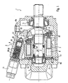
- Fig. 1 shows an axial section through a Axial piston machine 1 in swash plate design, at which is an adjusting device 2 according to the invention is provided.
- the basic structure of a Axial piston machine 1 in swash plate design is known, so that the following description on the restrict essential components.
- a shaft 3 is at a first bearing 4 and at a second bearing 5 in a housing 6 of the axial piston machine 1 rotatably mounted.
- the housing 6 of the axial piston machine 1 is divided into a main body 6a and one with the Base 6a bolted lid body 6b.
- a cylinder drum 7 is rotationally fixed to the shaft 3 connected.
- the cylinder drum 7 are on one Partial circle offset cylinder bores 8, in which piston 9 are axially displaceable.
- the pistons 9 are via ball joint connections 10 with sliding shoes 11 connected and rely on the shoes 11 on a as swivel cradle trained swash plate 12 from.
- the stroke of the piston 9 in the cylinder bores 8 is by the tilt angle ⁇ of the swash plate 12th specified.
- the swivel disc designed as a swivel cradle is in Fig. 1 in its neutral position and one to the Swivel angle ⁇ pivoted position twice shown.
- the cylinder drum 7 is by means of a spring 22 on the Control body 13 held in contact. This is supported by the Spring 22 via a first ring 23 on the cylinder drum. 7 and via a second ring 24 on the shaft 3 from.
- the Cylinder drum 7 is opposite to the stationary shaft 3 via a wedge-groove connection axially movable.
- Adjustment device For pivoting the swash plate 12 is used Adjustment device according to the invention 2.
- the Adjustment device 2 is in a receiving bore 16 of the Housing 6 is integrated and consists of a over the Ball joint 17 with the swash plate 12th connected adjusting piston 18, which in the receiving bore 16 is guided axially, one in the receiving bore 16th used control valve 19 and a control force for a valve piston 20 of the control valve 19 predetermining Actuator 21.
- the control valve 19 and the actuating piston are axially offset from each other in the receiving bore 16 arranged.
- Adjustment device 2 is shown enlarged in Fig. 2.
- the embodiment is substantially the same as in Fig. 1 illustrated embodiment, with the Difference that in the illustrated in Fig. 2 Embodiment, an adjusting screw 30 is provided whose function will be discussed later. Otherwise are with Fig. 1 matching elements with matching Provided with reference numerals to facilitate the assignment.
- a spherical sliding block 31 At the in the receiving bore 16 of the housing 6 axially Guided actuator piston 18 is a spherical sliding block 31, which together with a in Fig. 1 shown spherical recess of the swash plate 12th the ball joint 17 forms.
- the sliding block 31 at the Swash plate 12 slidably abut and the spherical Recess may be formed in the actuating piston 18.
- the Control piston 18 is cup-shaped, so that his Wall 32 surrounds a cavity 33, which a Return spring 34 for the valve piston 20 of the closer to descriptive control valve 19 receives.
- the Return spring 34 is between the bottom 35 of the pot-shaped actuating piston 18 and a spring plate 39 clamped, which with a first end 40 of the Valve piston 20 of the control valve 19 is connected.
- the Spring plate 39 has an axial longitudinal bore 41, which on a pin-shaped projection 42 of the Valve piston 20 is attached.
- the return spring 35 is supported on an outside step 43 of the Spring plate 39 from.
- For lubrication of the sliding surface of the Control piston 32 is an outside annular groove 44th provided, which via a radial channel 68 with the Cavity 33 is connected.
- the annular groove 44 also serves as hydraulic stop.
- the diameter of the cavity 33 is larger than the diameter of the spring plate 39 dimensioned so that the spring plate 39 in the in Fig. 2 illustrated maximum pivotal position of the cavity 33rd the adjusting piston 18 is received.
- control volume 45 which the cavity 33 of the Adjusting piston 18 includes, adjusts itself from the Actuator 21 via the control valve 19 predetermined Setting pressure.
- the control valve 19 consists of a fixed, sleeve-shaped connector body 46, in which a Tank connection 47 and a pressure connection 48 are formed.
- the connection body 46 is via a seal 49, For example, an O-ring, relative to the housing. 6 sealed.
- a valve sleeve 50 in which the valve piston 20 axially is movable.
- the valve piston 20, the valve sleeve 50, the Connection body 46 and the receiving bore 16 of the housing 6, in which the control valve 19 is inserted, are aligned coaxially with each other.
- valve sleeve 50 In the valve sleeve 50 is a connection channel 51, in the embodiment consisting of a as Blind bore trained longitudinal bore 52 and a Transverse hole 53.
- the connecting channel 51 is over a Throttle 54 connected to the tank port 47.
- the valve sleeve 50 In the area the tank port 47, the valve sleeve 50 a first annular channel 55, while the valve sleeve 50 in Area of the pressure port 48 a second annular channel 56th having.
- the valve piston 20 has a first with the Pressure port 48 via a first radial bore 56th connected annular space 57, which has a Sealing portion 58 and a radial projection 59 of the Valve piston 20 is sealed. Furthermore, the Valve piston 20 a via a second radial bore 60 with the tank port 47 connected annular space 61, which via a sealing portion 62 and a radial projection 63 of the valve piston 20 is sealed. At the transition from the first annulus 57 to the projection 59 is thereby a first control edge 64 formed while on the Transition from the second annulus 51 to the projection 63rd a second control edge 65 is formed.
- the actuator 21 exerts a control force on a plunger 66 on the Return spring 34 opposite the second end 67 of Actuating piston 20 off.
- Adjustment device 2 The operation of the invention Adjustment device 2 is as follows:
- actuator 21 is particularly suitable an electromagnet, In particular, a proportional magnet whose force or Deflection proportional to the exciting electric current is.
- actuator 21 is also a Electric motor, in particular a stepper motor, which for example, via a spindle and between the Plunger 66 and the spindle arranged spring on the plunger 66 one of the rotational position of the electric motor proportional Control force transfers.
- 20 applied control force can also be a hydraulic Be force, which in one at the end 67 of the Valve piston 20 trained pressure chamber prevails and on the left in Fig. 2 end face of the valve piston 20th acts.
- a adjustable stop 70 is provided, wherein a Andschreibfeder 71, the valve sleeve 50 on the adjustable Stop 70 stops in abutment.
- the adjustable stop 70 By the adjustable stop 70, the relative position of the control edges 64 and 65 in FIG Reference to the transverse bore 53 of the connecting channel 51st be adjusted.
- the adjustable stop 70 consists of one in the Housing 6 screwed adjusting screw 30 with Screw head 72 and lock nut 73.
- valve piston 20 In the valve piston 20 is located in the illustrated Embodiment, a passageway 76, the Stellvolumen 45 with the spring chamber 77, which the Compressing spring 71 receives, connects.
- a passageway 76, the Stellvolumen 45 with the spring chamber 77, which the Compressing spring 71 receives connects.
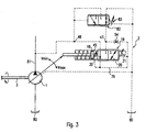
- FIG. 3 a Hydraulic block diagram of the invention Adjustment device 2 shown. Already described Elements are also here with matching reference numerals Mistake.
- the working in the embodiment as a hydraulic pump Axial piston machine 1 is driven via the shaft 3, sucks hydraulic fluid from a tank 80 and promotes that Hydraulic fluid in a working line 81.
- the Working line 81 is connected to the pressure port 48 of Adjustment device 2 connected.
- the Tank connection 47 of the adjusting device 2 via a Pressure relief valve 82 either with the tank 80 or with the working line 81 connected.
- the pressure relief valve 82 In the in Fig. 3rd illustrated basic position of the pressure relief valve 82nd the pressure relief valve 82 connects the tank port 47 with the tank 80.
- the pressure limiting valve 82 serves to limit the pressure prevailing in the working line 81 to a maximum pressure. If the pressure prevailing in the working line 81 exceeds the maximum pressure which can be set by means of the spring 83, the pressure limiting valve 82 connects the tank connection 47, instead of the tank 80 with the working line 81, so that the adjusting volume 45 is not relieved to the tank 80, but with the working pressure prevailing in the working line 81 is applied. The axial piston machine 1 is therefore pivoted back by the adjusting piston 18 in the direction of minimum displacement volume V min or in the direction of the neutral position.
- V max designates the maximum displacement volume which occurs when the actuating piston 18 in FIG. 2 abuts against its left stop.
- the invention is not limited to those shown Embodiments limited, but can also at an adjusting device 2 in a different construction or at Axial piston machines 1 in a different design for use come. It should be emphasized that the adjustment of the Control piston 18 regardless of the adjustment of the Valve piston 20 is and despite a very small Adjustment of the valve piston 20 a very large Can reach adjustment of the actuating piston 18. A Translation of the adjustment of the actuating piston 18 is therefore not required.
Landscapes
- Engineering & Computer Science (AREA)
- Mechanical Engineering (AREA)
- General Engineering & Computer Science (AREA)
- Reciprocating Pumps (AREA)
Claims (12)
- Dispositif de déplacement pour déplacer le plateau oblique (12) d'un moteur à pistons axiaux (1) en mode de construction à plateau oblique, comportant un piston de positionnement (18) attaquant le plateau oblique (21) du moteur à pistons axiaux (1) ainsi qu'une valve de commande (19) pour régler la pression de réglage régnant dans un volume de réglage (45) et agissant sur le piston de positionnement (18), en fonction d'une force de commande agissant sur le piston de valve (20) de la valve de commande (19), le piston de positionnement (18) étant structurellement séparé de la valve de commande (19),
caractérisé en ce que
le piston de positionnement (18) est relié au piston de valve (20) de la valve de commande (19) par un ressort de rappel (34) agissant à l'encontre de la force de commande,
et en ce que le piston de positionnement (18) et la valve de commande (19) sont susceptibles d'être mis en place en décalage axial mutuel dans un perçage de logement (16) d'un carter (6) du moteur à pistons axiaux (1). - Dispositif de déplacement selon la revendication 1, caractérisé en ce que la précontrainte du ressort de rappel (34) dépend de la position du piston de positionnement (18).
- Dispositif de déplacement selon la revendication 1 ou 2, caractérisé en ce que le ressort de rappel (34) est intégré dans une cavité (33) du piston de positionnement (18) réalisé en forme de pot.
- Dispositif de déplacement selon la revendication 3, caractérisé en ce que la cavité (33) du piston de positionnement (18) reçoit un appui de ressort (39) qui est relié au piston de valve (20), le ressort de rappel (34) étant serré entre le fond (35) du piston de positionnement (18) en forme de pot et l'appui de ressort (39).
- Dispositif de déplacement selon l'une des revendications 1 à 4, caractérisé en ce que le piston de valve (20) de la valve de commande (19) est mobile dans une douille de valve (50).
- Dispositif de déplacement selon la revendication 5, caractérisé en ce que la douille de valve (50) présente un canal de liaison (51) relié au volume de réglage (45) et le piston de valve (20) comprend une première arête de commande (64) pour relier le canal de liaison (51) à un raccord de pression (48) ainsi qu'une seconde arête de commande (65) pour relier le canal de liaison (51) à un raccord de réservoir (47).
- Dispositif de déplacement selon la revendication 5 ou 6, caractérisé en ce que la douille de valve (50) comprend un étranglement (54) pour relier le canal de liaison (51) par étranglement au raccord de réservoir (47).
- Dispositif de déplacement selon l'une des revendications 5 à 7, caractérisé en ce que le piston de valve (20) comprend un canal de passage (76) relié au volume de réglage (45), afin d'alimenter en pression de réglage la douille de valve (50) des deux côtés, de sorte que la position de la douille de valve (50) est indépendante de la pression de réglage et de la position du plateau oblique (12).
- Dispositif de déplacement selon l'une des revendications 5 à 8, caractérisé en ce que la douille de valve (50) est pressée par un ressort de pressage (71) contre une butée ajustable (70), la position axiale de la douille de valve (50) étant réglable au moyen de la butée ajustable (70).
- Dispositif de déplacement selon l'une des revendications 1 à 9, caractérisé en ce que la force de commande est générée par un électroaimant (21), en particulier par un aimant proportionnel.
- Dispositif de déplacement selon l'une des revendications 1 à 10, caractérisé en ce que la force de commande est générée par un moteur électrique, en particulier par un moteur pas à pas.
- Dispositif de déplacement selon la revendication 10 ou 11, caractérisé en ce que l'électroaimant (21) ou le moteur électrique est relié au piston de valve (20) par un poussoir (66) qui attaque le piston de valve (20) à une extrémité (67) opposée au ressort de rappel (34).
Applications Claiming Priority (3)
| Application Number | Priority Date | Filing Date | Title |
|---|---|---|---|
| DE19949169 | 1999-10-12 | ||
| DE19949169A DE19949169C2 (de) | 1999-10-12 | 1999-10-12 | Verstellvorrichtung |
| PCT/EP2000/009566 WO2001027472A1 (fr) | 1999-10-12 | 2000-09-29 | Dispositif de reglage d'une machine a piston axial a plateau en biais |
Publications (2)
| Publication Number | Publication Date |
|---|---|
| EP1220990A1 EP1220990A1 (fr) | 2002-07-10 |
| EP1220990B1 true EP1220990B1 (fr) | 2005-11-16 |
Family
ID=7925374
Family Applications (1)
| Application Number | Title | Priority Date | Filing Date |
|---|---|---|---|
| EP00971304A Expired - Lifetime EP1220990B1 (fr) | 1999-10-12 | 2000-09-29 | Dispositif de réglage pour une machine à piston axial à plateau en biais |
Country Status (5)
| Country | Link |
|---|---|
| US (1) | US6725658B1 (fr) |
| EP (1) | EP1220990B1 (fr) |
| JP (1) | JP4691299B2 (fr) |
| DE (2) | DE19949169C2 (fr) |
| WO (1) | WO2001027472A1 (fr) |
Cited By (4)
| Publication number | Priority date | Publication date | Assignee | Title |
|---|---|---|---|---|
| RU201392U1 (ru) * | 2020-08-11 | 2020-12-11 | Публичное акционерное общество "Авиационная корпорация "Рубин" | Аксиально-поршневой насос с регулируемой подачей и задемпфированным золотником |
| US10954927B2 (en) | 2015-11-15 | 2021-03-23 | Eaton Intelligent Power Limited | Hydraulic pump control system |
| US11066932B2 (en) | 2019-06-26 | 2021-07-20 | Robert Bosch Gmbh | Actuating cylinder for a hydrostatic axial piston machine and hydrostatic axial piston machine with an actuating cylinder |
| US11828276B2 (en) | 2017-11-11 | 2023-11-28 | Liebherr Machines Bulle Sa | Adjusting device for an axial piston machine |
Families Citing this family (41)
| Publication number | Priority date | Publication date | Assignee | Title |
|---|---|---|---|---|
| DE10001826C1 (de) | 2000-01-18 | 2001-09-20 | Brueninghaus Hydromatik Gmbh | Vorrichtung zum Regeln der Leistung einer verstellbaren Kolbenmaschine |
| DE10341331B3 (de) * | 2003-09-08 | 2005-05-25 | Brueninghaus Hydromatik Gmbh | Leistungsregelvorrichtung |
| DE10360452B3 (de) * | 2003-12-22 | 2005-09-08 | Brueninghaus Hydromatik Gmbh | Axialkolbenmaschine mit fixierbarem Gleitstein an der Schrägscheibe |
| DE102005059808B3 (de) * | 2005-12-14 | 2007-06-14 | Sauer-Danfoss Gmbh & Co Ohg | Axialkolbenmaschine mit einer Verstelleinheit zur elektrisch proportionalen Verstellung des Fördervolumens |
| DE102006061145A1 (de) * | 2006-12-22 | 2008-06-26 | Robert Bosch Gmbh | Hydrostatische Axialkolbenmaschine |
| CN101815865B (zh) * | 2007-08-20 | 2012-06-27 | 罗伯特-博世有限公司 | 位于具有调节装置的旋转斜盘结构中的轴向活塞机构 |
| DE102007039589A1 (de) * | 2007-08-22 | 2009-02-26 | Voigt, Dieter, Dipl.-Ing. | Regelölpumpe mit verstellwegabhängiger Öldruckregelung |
| DE102007044451A1 (de) | 2007-09-18 | 2009-03-19 | Robert Bosch Gmbh | Anschlussplatte für eine hydrostatische Kolbenmaschine |
| DE102009006909B4 (de) | 2009-01-30 | 2019-09-12 | Robert Bosch Gmbh | Axialkolbenmaschine mit reduzierter Stelldruckpulsation |
| DE102009012560B4 (de) | 2009-03-11 | 2019-09-12 | Robert Bosch Gmbh | Ventilvorrichtung für eine Regelungsvorrichtung |
| US8635941B2 (en) | 2009-10-26 | 2014-01-28 | Caterpillar Inc. | Method and apparatus for controlling a pump |
| DE102011113533A1 (de) | 2011-09-15 | 2013-03-21 | Robert Bosch Gmbh | Hydrostatische Axialkolbenmaschine |
| DE102012021320A1 (de) * | 2012-10-31 | 2014-04-30 | Robert Bosch Gmbh | Verstellvorrichtung für eine hydrostatische Kolbenmaschine und hydrostatische Kolbenmaschine mit einer derartigen Verstellvorrichtung |
| DE102012022201A1 (de) * | 2012-11-13 | 2014-05-15 | Robert Bosch Gmbh | Verstellvorrichtung für eine Axialkolbenmaschine und Hydromaschine mit einer derartigen Verstellvorrichtung |
| DE102012022694A1 (de) * | 2012-11-20 | 2014-05-22 | Robert Bosch Gmbh | Regelventil, insbesondere für eine elektroproportionale Schwenkwinkelregelung einer Hydromaschine |
| DE102012022997A1 (de) * | 2012-11-24 | 2014-05-28 | Robert Bosch Gmbh | Verstelleinrichtung für eine Hydromaschine und hydraulische Axialkolbenmaschine |
| RU2524504C1 (ru) * | 2012-12-24 | 2014-07-27 | Дмитрий Александрович Фомин | Фрикционная предохранительная конусная муфта |
| DE102013206161A1 (de) * | 2013-04-08 | 2014-10-30 | Robert Bosch Gmbh | Axialkolbenmaschine |
| DE102013216395B4 (de) | 2013-08-19 | 2019-01-17 | Danfoss Power Solutions a.s. | Steuereinrichtung für hydraulische verstellpumpen und verstellpumpe mit einer steuereinrichtung |
| DE102014211189A1 (de) | 2013-11-21 | 2015-05-21 | Robert Bosch Gmbh | Hydrostatische Hydromaschine |
| DE102013224112B4 (de) | 2013-11-26 | 2024-01-18 | Robert Bosch Gmbh | Hydromaschine in Axialkolbenbauweise mit einer durch einen Proportionalmagneten verstellbaren Schrägscheiben-Stelleinrichtung |
| DE102013224113A1 (de) | 2013-11-26 | 2015-05-28 | Robert Bosch Gmbh | Hydromotor |
| DE102014202413A1 (de) | 2014-02-11 | 2015-08-13 | Robert Bosch Gmbh | Elektrisch angesteuertes Regelventil für eine verstellbare hydrostatische Pumpe und verstellbare hydrostatische Pumpe |
| DE102014202412A1 (de) | 2014-02-11 | 2015-08-13 | Robert Bosch Gmbh | Elektrisch angesteuertes Druckregelventil für eine verstellbare hydrostatische Pumpe und verstellbare hydrostatische Pumpe mit einem Druckregelventil |
| DE102014202411A1 (de) | 2014-02-11 | 2015-08-13 | Robert Bosch Gmbh | Elektrisch angesteuertes Druckregelventil für eine verstellbare hydrostatische Pumpe und eine verstellbare hydrostatische Pumpe mit einem Druckregelventil |
| DE102014226378A1 (de) | 2014-02-18 | 2015-08-20 | Robert Bosch Gmbh | Elektrisch angesteuertes Druckregelventil für eine verstellbare hydrostatische Pumpe |
| DE102014211194A1 (de) | 2014-06-12 | 2015-12-17 | Robert Bosch Gmbh | Hydrostatische Axialkolbenmaschine in Schrägscheibenbauweise und Lüfter mit einer hydrostatischen Axialkolbenmaschine |
| DE102014211202A1 (de) | 2014-06-12 | 2015-12-17 | Robert Bosch Gmbh | Hydrostatische Axialkolbenmaschine in Schrägscheibenbauweise und Lüfter mit einer hydro-statischen Axialkolbenmaschine |
| DE102015216176A1 (de) | 2014-08-27 | 2016-03-03 | Robert Bosch Gmbh | Hydrostatische Axialkolbenmaschine |
| CN107787408B (zh) | 2015-06-26 | 2019-12-06 | 凯斯帕公司 | 变量泵及其调节方法 |
| JP6811766B2 (ja) * | 2015-08-10 | 2021-01-13 | イートン インテリジェント パワー リミテッドEaton Intelligent Power Limited | 開回路ポンプのための電気油圧比例圧力制御 |
| JP6613135B2 (ja) | 2015-12-25 | 2019-11-27 | 川崎重工業株式会社 | 斜板ポンプの容量調整装置 |
| US10961998B2 (en) * | 2018-03-08 | 2021-03-30 | Hartmann Controls, Inc. | Electro-hydraulic swashplate control arrangement for an axial piston pump |
| DE102018212042A1 (de) * | 2018-07-19 | 2020-01-23 | Robert Bosch Gmbh | Hydromaschine mit geregeltem Verdrängungsvolumen |
| DE102018214481A1 (de) * | 2018-08-28 | 2020-03-05 | Robert Bosch Gmbh | Hydrostatische Verdrängermaschine |
| CN112343806B (zh) * | 2019-08-08 | 2023-08-29 | 丹佛斯动力系统公司 | 用于开放回路可变排量泵的电动排量控制 |
| DE102019215885A1 (de) * | 2019-10-16 | 2021-04-22 | Robert Bosch Gmbh | Verstelleinrichtung und Hydromaschine |
| CH717936A1 (de) * | 2020-10-06 | 2022-04-14 | Liebherr Machines Bulle Sa | Axialkolbenmaschine mit Steuerventil. |
| CN112302895A (zh) * | 2020-11-25 | 2021-02-02 | 力源液压(苏州)有限公司 | 一种轴向柱塞泵 |
| CN114087149B (zh) * | 2021-11-17 | 2023-12-05 | 重庆大学 | 一种双腔独立控制的柱塞泵变量控制回路及多模式切换控制方法 |
| JP2023140521A (ja) * | 2022-03-23 | 2023-10-05 | 川崎重工業株式会社 | 液圧回転機械および液圧ポンプ |
Family Cites Families (14)
| Publication number | Priority date | Publication date | Assignee | Title |
|---|---|---|---|---|
| FR1099156A (fr) | 1954-02-11 | 1955-08-31 | Pompe haute pression à réglage automatique de débit | |
| DE1958768B2 (de) * | 1969-11-22 | 1971-11-11 | Deere & Co., Moline, 111. (V.StA.) | Stelleinrichtung fuer einen stufenlos einstellbaren hydro motor eines hydrostatischen getriebes insbesondere fuer land wirtschaftliche maschinen und geraete |
| CH526977A (de) | 1970-09-15 | 1972-08-31 | Wepuko Werkzeug Pumpen Und Kom | Einrichtung für eine kontinuierliche Flüssig-Flüssig-Extraktion |
| JPS55151184A (en) * | 1979-05-15 | 1980-11-25 | Daikin Ind Ltd | Variable displacement type hydraulic apparatus |
| US4379389A (en) * | 1980-09-12 | 1983-04-12 | Caterpillar Tractor Co. | Horsepower consumption control for variable displacement pumps |
| CH660637A5 (en) | 1982-12-20 | 1987-05-15 | Sig Schweiz Industrieges | Arrangement for a hydraulic servocontrol |
| DE3346000A1 (de) | 1982-12-21 | 1984-06-28 | Linde Ag, 6200 Wiesbaden | Hydraulische stelleinrichtung fuer eine hydrostatische maschine |
| DE3404534A1 (de) | 1984-02-09 | 1985-09-05 | Mannesmann Rexroth GmbH, 8770 Lohr | Hydraulische antriebsanordnung |
| US4722186A (en) * | 1986-01-24 | 1988-02-02 | Sundstrand Corporation | Dual pressure displacement control system |
| DE3935800C2 (de) * | 1989-10-27 | 1997-03-27 | Linde Ag | Einstellbare Axialkolbenmaschine in Schrägscheibenbauweise |
| DE4327667A1 (de) | 1993-08-17 | 1995-02-23 | Sauer Sundstrand Gmbh & Co | Steuerungsvorrichtung für verstellbare Hydromaschinen |
| JPH09177704A (ja) * | 1995-12-25 | 1997-07-11 | Toyota Autom Loom Works Ltd | 塵芥収集車 |
| DE19653165C2 (de) * | 1996-12-19 | 2002-04-25 | Brueninghaus Hydromatik Gmbh | Verstelleinrichtung zur Verstellung des Fördervolumens einer Axialkolbenpumpe |
| JPH10232716A (ja) * | 1997-02-18 | 1998-09-02 | Toshiba Mach Co Ltd | 電磁減圧弁 |
-
1999
- 1999-10-12 DE DE19949169A patent/DE19949169C2/de not_active Expired - Fee Related
-
2000
- 2000-09-29 WO PCT/EP2000/009566 patent/WO2001027472A1/fr active IP Right Grant
- 2000-09-29 EP EP00971304A patent/EP1220990B1/fr not_active Expired - Lifetime
- 2000-09-29 JP JP2001529585A patent/JP4691299B2/ja not_active Expired - Fee Related
- 2000-09-29 US US10/110,575 patent/US6725658B1/en not_active Expired - Lifetime
- 2000-09-29 DE DE50011655T patent/DE50011655D1/de not_active Expired - Lifetime
Cited By (4)
| Publication number | Priority date | Publication date | Assignee | Title |
|---|---|---|---|---|
| US10954927B2 (en) | 2015-11-15 | 2021-03-23 | Eaton Intelligent Power Limited | Hydraulic pump control system |
| US11828276B2 (en) | 2017-11-11 | 2023-11-28 | Liebherr Machines Bulle Sa | Adjusting device for an axial piston machine |
| US11066932B2 (en) | 2019-06-26 | 2021-07-20 | Robert Bosch Gmbh | Actuating cylinder for a hydrostatic axial piston machine and hydrostatic axial piston machine with an actuating cylinder |
| RU201392U1 (ru) * | 2020-08-11 | 2020-12-11 | Публичное акционерное общество "Авиационная корпорация "Рубин" | Аксиально-поршневой насос с регулируемой подачей и задемпфированным золотником |
Also Published As
| Publication number | Publication date |
|---|---|
| DE19949169A1 (de) | 2001-04-26 |
| DE19949169C2 (de) | 2001-10-11 |
| JP2003511628A (ja) | 2003-03-25 |
| EP1220990A1 (fr) | 2002-07-10 |
| US6725658B1 (en) | 2004-04-27 |
| JP4691299B2 (ja) | 2011-06-01 |
| DE50011655D1 (de) | 2005-12-22 |
| WO2001027472A1 (fr) | 2001-04-19 |
Similar Documents
| Publication | Publication Date | Title |
|---|---|---|
| EP1220990B1 (fr) | Dispositif de réglage pour une machine à piston axial à plateau en biais | |
| DE102009006909B4 (de) | Axialkolbenmaschine mit reduzierter Stelldruckpulsation | |
| DE4396844C2 (de) | Vorrichtung zur Steuerung von Druck in den Zylinderkammern von hydraulischen Pumpen und Motoren | |
| DE19842029B4 (de) | Verstellung von hydrostatischen Axialkolbenmaschinen mittels Schrittmotor | |
| DE1453428A1 (de) | Steuervorrichtung fuer hydraulische Pumpen oder Motoren | |
| EP1636459B1 (fr) | Moteur a pistons axiaux reversible a reglage longitudinal | |
| DE10001826C1 (de) | Vorrichtung zum Regeln der Leistung einer verstellbaren Kolbenmaschine | |
| WO2008017557A1 (fr) | Machine à pistons axiaux | |
| DE4447129B4 (de) | Hydrostatisches Getriebe, Verfahren zum Steuern eines hydrostatischen Getriebes | |
| WO2005064159A1 (fr) | Moteur a pistons axiaux comportant un coulisseau pouvant etre fixe sur le plateau oscillant | |
| EP1438504B8 (fr) | Moteur a piston alternatif a manchon coulissant | |
| DE102008035133B4 (de) | Hydrostatische Maschine mit einer Stellvorrichtung zur Verstellung des Hubvolumens | |
| DE3725411C2 (fr) | ||
| DE2100117B2 (de) | Steuerventil für eine hydraulische Stelleinrichtung zur Verstellung eines schwenkbaren Bauteils | |
| DE2531492C2 (de) | Verstellbare hydrostatische Pumpe | |
| DE2660561C2 (de) | Steuervorrichtung fuer axialkolbenmaschinen | |
| DE102018214481A1 (de) | Hydrostatische Verdrängermaschine | |
| DE102008050835B4 (de) | Hydrostatische Verdrängermaschine mit einem verstellbaren Verdrängervolumen und mit einem in den Stellkolben integrierten und durch die Stellkolben-Rückstellfeder beaufschlagten Stelldruckregelventil | |
| DE10348560A1 (de) | Elektrohydraulische Pumpenverdrängungssteuerung mit proportionaler Kraftrückkoppelung | |
| DE3919175A1 (de) | Regeleinrichtung fuer eine verstellbare pumpe | |
| EP1090229B1 (fr) | Systeme de commande pour equipement hydraulique | |
| DE1500327B1 (de) | Stellgerät für eine stufenlos einstellbare Pumpe eines hydrostatischen Getriebes | |
| DE2337481C2 (de) | Folgesteuereinrichtung für eine verstellbare Pumpe | |
| DE2947651A1 (de) | Pumpe oder motor mit veraenderlicher verdraengung | |
| DE19960569A1 (de) | Pumpe für variable Lieferung mit fester Verdrängung |
Legal Events
| Date | Code | Title | Description |
|---|---|---|---|
| PUAI | Public reference made under article 153(3) epc to a published international application that has entered the european phase |
Free format text: ORIGINAL CODE: 0009012 |
|
| 17P | Request for examination filed |
Effective date: 20020312 |
|
| AK | Designated contracting states |
Kind code of ref document: A1 Designated state(s): AT BE CH CY DE DK ES FI FR GB GR IE IT LI LU MC NL PT SE |
|
| RIN1 | Information on inventor provided before grant (corrected) |
Inventor name: LEMMEN, DR. RALF Inventor name: BELSER, ROLAND Inventor name: MAIER, HERMANN |
|
| RBV | Designated contracting states (corrected) |
Designated state(s): DE FR GB IT SE |
|
| 17Q | First examination report despatched |
Effective date: 20040608 |
|
| GRAP | Despatch of communication of intention to grant a patent |
Free format text: ORIGINAL CODE: EPIDOSNIGR1 |
|
| RTI1 | Title (correction) |
Free format text: ADJUSTING DEVICE FOR A SWASH-PLATE PISTON MACHINE |
|
| GRAS | Grant fee paid |
Free format text: ORIGINAL CODE: EPIDOSNIGR3 |
|
| GRAA | (expected) grant |
Free format text: ORIGINAL CODE: 0009210 |
|
| AK | Designated contracting states |
Kind code of ref document: B1 Designated state(s): DE FR GB IT SE |
|
| REG | Reference to a national code |
Ref country code: GB Ref legal event code: FG4D Free format text: NOT ENGLISH |
|
| GBT | Gb: translation of ep patent filed (gb section 77(6)(a)/1977) | ||
| REF | Corresponds to: |
Ref document number: 50011655 Country of ref document: DE Date of ref document: 20051222 Kind code of ref document: P |
|
| REG | Reference to a national code |
Ref country code: SE Ref legal event code: TRGR |
|
| ET | Fr: translation filed | ||
| PLBE | No opposition filed within time limit |
Free format text: ORIGINAL CODE: 0009261 |
|
| STAA | Information on the status of an ep patent application or granted ep patent |
Free format text: STATUS: NO OPPOSITION FILED WITHIN TIME LIMIT |
|
| 26N | No opposition filed |
Effective date: 20060817 |
|
| PGFP | Annual fee paid to national office [announced via postgrant information from national office to epo] |
Ref country code: SE Payment date: 20120920 Year of fee payment: 13 Ref country code: GB Payment date: 20120920 Year of fee payment: 13 |
|
| PGFP | Annual fee paid to national office [announced via postgrant information from national office to epo] |
Ref country code: FR Payment date: 20121008 Year of fee payment: 13 |
|
| REG | Reference to a national code |
Ref country code: SE Ref legal event code: EUG |
|
| PG25 | Lapsed in a contracting state [announced via postgrant information from national office to epo] |
Ref country code: SE Free format text: LAPSE BECAUSE OF NON-PAYMENT OF DUE FEES Effective date: 20130930 |
|
| GBPC | Gb: european patent ceased through non-payment of renewal fee |
Effective date: 20130929 |
|
| REG | Reference to a national code |
Ref country code: FR Ref legal event code: ST Effective date: 20140530 |
|
| PG25 | Lapsed in a contracting state [announced via postgrant information from national office to epo] |
Ref country code: GB Free format text: LAPSE BECAUSE OF NON-PAYMENT OF DUE FEES Effective date: 20130929 |
|
| PG25 | Lapsed in a contracting state [announced via postgrant information from national office to epo] |
Ref country code: FR Free format text: LAPSE BECAUSE OF NON-PAYMENT OF DUE FEES Effective date: 20130930 |
|
| PGFP | Annual fee paid to national office [announced via postgrant information from national office to epo] |
Ref country code: IT Payment date: 20150925 Year of fee payment: 16 |
|
| PGFP | Annual fee paid to national office [announced via postgrant information from national office to epo] |
Ref country code: DE Payment date: 20161125 Year of fee payment: 17 |
|
| PG25 | Lapsed in a contracting state [announced via postgrant information from national office to epo] |
Ref country code: IT Free format text: LAPSE BECAUSE OF NON-PAYMENT OF DUE FEES Effective date: 20160929 |
|
| REG | Reference to a national code |
Ref country code: DE Ref legal event code: R119 Ref document number: 50011655 Country of ref document: DE |
|
| PG25 | Lapsed in a contracting state [announced via postgrant information from national office to epo] |
Ref country code: DE Free format text: LAPSE BECAUSE OF NON-PAYMENT OF DUE FEES Effective date: 20180404 |