EP1220146A1 - Verfahren zur thermischen Stabilierung einer Laserdiode in einem Recorder - Google Patents
Verfahren zur thermischen Stabilierung einer Laserdiode in einem Recorder Download PDFInfo
- Publication number
- EP1220146A1 EP1220146A1 EP01126905A EP01126905A EP1220146A1 EP 1220146 A1 EP1220146 A1 EP 1220146A1 EP 01126905 A EP01126905 A EP 01126905A EP 01126905 A EP01126905 A EP 01126905A EP 1220146 A1 EP1220146 A1 EP 1220146A1
- Authority
- EP
- European Patent Office
- Prior art keywords
- laser diode
- during
- modulated
- current
- exposure
- Prior art date
- Legal status (The legal status is an assumption and is not a legal conclusion. Google has not performed a legal analysis and makes no representation as to the accuracy of the status listed.)
- Granted
Links
- 230000006641 stabilisation Effects 0.000 title claims abstract description 24
- 238000000034 method Methods 0.000 title claims abstract description 23
- 238000011105 stabilization Methods 0.000 claims abstract description 23
- 230000008569 process Effects 0.000 claims description 2
- 238000011084 recovery Methods 0.000 claims 1
- 238000005286 illumination Methods 0.000 abstract 2
- 230000000087 stabilizing effect Effects 0.000 abstract 1
- 238000007639 printing Methods 0.000 description 19
- 238000010586 diagram Methods 0.000 description 9
- 238000012937 correction Methods 0.000 description 4
- 230000008859 change Effects 0.000 description 3
- 230000003287 optical effect Effects 0.000 description 3
- 238000002360 preparation method Methods 0.000 description 3
- 238000005516 engineering process Methods 0.000 description 2
- 230000009467 reduction Effects 0.000 description 2
- 230000007704 transition Effects 0.000 description 2
- 230000033228 biological regulation Effects 0.000 description 1
- 230000008878 coupling Effects 0.000 description 1
- 238000010168 coupling process Methods 0.000 description 1
- 238000005859 coupling reaction Methods 0.000 description 1
- 230000001934 delay Effects 0.000 description 1
- 230000001419 dependent effect Effects 0.000 description 1
- 238000013461 design Methods 0.000 description 1
- 238000011161 development Methods 0.000 description 1
- 230000018109 developmental process Effects 0.000 description 1
- 230000000694 effects Effects 0.000 description 1
- 230000017525 heat dissipation Effects 0.000 description 1
- 238000009434 installation Methods 0.000 description 1
- 238000001208 nuclear magnetic resonance pulse sequence Methods 0.000 description 1
- 238000012545 processing Methods 0.000 description 1
- 230000001105 regulatory effect Effects 0.000 description 1
- 230000035945 sensitivity Effects 0.000 description 1
- 230000002123 temporal effect Effects 0.000 description 1
- 238000009423 ventilation Methods 0.000 description 1
Images


Classifications
-
- B—PERFORMING OPERATIONS; TRANSPORTING
- B41—PRINTING; LINING MACHINES; TYPEWRITERS; STAMPS
- B41J—TYPEWRITERS; SELECTIVE PRINTING MECHANISMS, i.e. MECHANISMS PRINTING OTHERWISE THAN FROM A FORME; CORRECTION OF TYPOGRAPHICAL ERRORS
- B41J2/00—Typewriters or selective printing mechanisms characterised by the printing or marking process for which they are designed
- B41J2/435—Typewriters or selective printing mechanisms characterised by the printing or marking process for which they are designed characterised by selective application of radiation to a printing material or impression-transfer material
- B41J2/47—Typewriters or selective printing mechanisms characterised by the printing or marking process for which they are designed characterised by selective application of radiation to a printing material or impression-transfer material using the combination of scanning and modulation of light
- B41J2/471—Typewriters or selective printing mechanisms characterised by the printing or marking process for which they are designed characterised by selective application of radiation to a printing material or impression-transfer material using the combination of scanning and modulation of light using dot sequential main scanning by means of a light deflector, e.g. a rotating polygonal mirror
-
- H—ELECTRICITY
- H01—ELECTRIC ELEMENTS
- H01S—DEVICES USING THE PROCESS OF LIGHT AMPLIFICATION BY STIMULATED EMISSION OF RADIATION [LASER] TO AMPLIFY OR GENERATE LIGHT; DEVICES USING STIMULATED EMISSION OF ELECTROMAGNETIC RADIATION IN WAVE RANGES OTHER THAN OPTICAL
- H01S5/00—Semiconductor lasers
- H01S5/06—Arrangements for controlling the laser output parameters, e.g. by operating on the active medium
- H01S5/062—Arrangements for controlling the laser output parameters, e.g. by operating on the active medium by varying the potential of the electrodes
- H01S5/06209—Arrangements for controlling the laser output parameters, e.g. by operating on the active medium by varying the potential of the electrodes in single-section lasers
- H01S5/06213—Amplitude modulation
-
- H—ELECTRICITY
- H01—ELECTRIC ELEMENTS
- H01S—DEVICES USING THE PROCESS OF LIGHT AMPLIFICATION BY STIMULATED EMISSION OF RADIATION [LASER] TO AMPLIFY OR GENERATE LIGHT; DEVICES USING STIMULATED EMISSION OF ELECTROMAGNETIC RADIATION IN WAVE RANGES OTHER THAN OPTICAL
- H01S5/00—Semiconductor lasers
- H01S5/06—Arrangements for controlling the laser output parameters, e.g. by operating on the active medium
- H01S5/062—Arrangements for controlling the laser output parameters, e.g. by operating on the active medium by varying the potential of the electrodes
- H01S5/06209—Arrangements for controlling the laser output parameters, e.g. by operating on the active medium by varying the potential of the electrodes in single-section lasers
- H01S5/06216—Pulse modulation or generation
-
- H—ELECTRICITY
- H01—ELECTRIC ELEMENTS
- H01S—DEVICES USING THE PROCESS OF LIGHT AMPLIFICATION BY STIMULATED EMISSION OF RADIATION [LASER] TO AMPLIFY OR GENERATE LIGHT; DEVICES USING STIMULATED EMISSION OF ELECTROMAGNETIC RADIATION IN WAVE RANGES OTHER THAN OPTICAL
- H01S5/00—Semiconductor lasers
- H01S5/06—Arrangements for controlling the laser output parameters, e.g. by operating on the active medium
- H01S5/068—Stabilisation of laser output parameters
Definitions
- the invention relates to the field of electronic reproduction technology and relates to a method for the thermal stabilization of a laser diode in the point and line-wise exposure of recording material by means of a light beam in an electronic exposure device, too Imagesetters, recorders or imagesetters.
- a recorder in particular Printing forms exposed, i.e. Films or printing plates, all text, Contain graphic and image elements of a page to be printed.
- Multi-color printing a separate printing form is exposed for each printing ink.
- a light beam modulated by an image signal is pinpointed line by line over the recording material to be exposed.
- the Recording material is fixed on a holder that is relative to Beam of light moves.
- the recording material is on a cylindrical segment-shaped holder or exposure trough fixed, and the light beam is by means of a rotating light beam deflecting device point and line over the recording material.
- the recorder can also be used as an outer drum device or a flat bed device be trained.
- a laser diode is often used as the light source for generating the light beam used, which is modulated with the image signal.
- image signal has only two signal values, Color or non-color or exposure or non-exposure. Accordingly the laser diode is modulated during the exposure so that it is for the illuminating pixels emits light and for the pixels not to be exposed emits no light.
- the control of the laser diode by the image signal takes place according to the prior art in such a way that they line by line within of exposure periods in which the light beam is the lines to be exposed is covered, activated and modulated on the recording material and within from return periods in which the light beam to the next line to be exposed is deactivated.
- a known problem with exposure to a laser diode is that the emitted light output and also the wavelength with the temperature of the laser diode changes.
- Different time constants apply for the temperature change, very short time constants when the temperature of the PN junction in the laser diode by switching the modulation current on and off changes very quickly, mean time constants when the temperature changes components of the laser diode due to a varying average current load changed, and a long time constant when, for example, the Ambient temperature changes.
- the short, medium and long time constants are not clearly delineated, but there is one smooth transition between temperature dependencies with different Time constants. In individual cases, this depends heavily on the structure of the laser diode, i.e.
- the temperature time constants from the constructive Design of the installation of the laser diode in the recorder, from the Heat dissipation through the components of the recorder and influenced by the ventilation.
- a constant light output is essential for the exposure of printing forms, as there are fluctuations in light output in unwanted stripes, patterns etc. in the finished exposed printing form. Furthermore can be a wavelength that changes as a result of temperature fluctuations produce similar disturbing patterns, depending on the dependence of the exposure sensitivity of the recording material on the wavelength of the Light.
- time constants become a regulation of the light output used, with part of the light beam from the exposure beam path uncoupled and directed to a light sensor.
- the one with the light sensor measured light output is entered as a measured variable in a control loop, which regulates the power of the laser diode to a predetermined value. This is done, for example, during a control phase before each modulation phase the light output measured at a given laser diode current and the Laser power regulated.
- One such method is in the American patent US 5,495,463.
- the control method is mainly used to compensate for relatively slow ones Temperature changes from modulation phase to modulation phase are suitable.
- one line to be exposed corresponds to one Modulation phase.
- the control process can only be exposed in front of everyone Intervene in the line and compensate for deviations.
- the control procedure is also complex to implement, especially if there are fluctuations in performance should be corrected from line to line by the of the image content dependent number and also the distribution of the image points to be exposed.
- the correction current method is only for very short power fluctuations in the time range of one or suitable for a few pixels and therefore cannot withstand the fluctuations in performance compensate with a medium time constant.
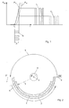
- 1 shows the modulation of a laser diode in a current-power diagram in which the optical output power P opt of a laser diode is plotted as a function of the diode current l.
- 1 shows a first curve P T1 (I) for a temperature T1 and a second curve P T2 (I) for a temperature T2> T1.
- the curves show the typical behavior for a laser diode, ie a light output is only emitted above a threshold current and the light output then increases sharply as the current increases.
- the light output only begins at a higher threshold current, ie the curve P T2 (I) is essentially shifted relative to the curve P T1 (I).
- the laser diode is usually modulated by superimposing a base current I B and a modulation current I M.
- the modulation current is a rectangular pulse sequence with the amplitude A, which reproduces the image signal of the pixels to be exposed and not to be exposed.
- Fig. 1 illustrates that a high light output of the output pulses is obtained for the temperature T1 and a lower light output for the higher temperature T2.
- Fig. 2 shows an exposure device in a sectional view, which works on the inner drum principle.
- the recording material 1 is fixed on the inner surface of a stationary cylindrical segment-shaped holder or exposure trough 2 with an opening angle of, for example, 180 °.
- the light beam 3 generated by a laser diode, not shown, is directed with a rotating light beam deflection device 4 in the direction of an arrow (line direction) on a circular path point by point and line by line over the recording material 1, the laser diode with the superimposition of the base current IB and the modulation current I M is modulated and the light beam deflection device 4 moves in the direction of the cylinder axis 5 perpendicular to the plane of the drawing (feed direction).
- the light beam deflection device 4 is, for example, a mirror oriented obliquely to the cylinder axis 5 and rotates about the cylinder axis 5.
- an exposure area 6 extends over the recording material 1.
- the exposure area 6 identifies the exposure period or modulation period in which the light beam 3 exposes a line on the recording material 1.
- the exposure area 6 results from the line length of the printing form to be exposed and, depending on the format of the printing page, can be smaller than the available width of the recording material.
- the exposure area 6 begins behind an initial marking 7 at the opening angle 0 ° and ends before an end marking 8 at the opening angle 180 °.
- the base current I B is switched on during an exposure period 10 in which the light beam is in the exposure area 6.
- the modulation current I M derived from the image signal is superimposed.
- the base current I B is only switched on during the exposure period 10 because the laser diode can emit a low light output even at the base current. If the base current were switched on outside the exposure period 10, an undesired exposure of the recording material 1 could take place outside the printing format.
- a stabilization period 12 is provided within the return period 11, in which the base current I B is additionally switched on in order to heat the laser diode also during the return period 11 and to avoid the temperature drop.
- the laser diode emits no or only very little optical power at the base current I B alone, a power loss is absorbed which is essentially equal to the total power determined by the current and voltage at the diode and which heats the laser diode.
- the output optical power P opt shown in FIG. 1 is only a small fraction of the total power consumed in typical laser diodes.
- the length of the stabilization period 12 is preferably chosen such that the sum of the exposure period 10 and the stabilization period 12 remains constant for all line lengths which result from the different formats of the exposed printing forms, that is, for example, corresponds to the maximum possible line length. That is, for for a printing form with a long line length, the stabilization period 12 is selected correspondingly shorter than for a printing form with a small line length.
- the base current is always switched on for the same length of time, regardless of the format of the exposed printing form, during a full revolution of the light beam deflection device 4, as a result of which the operating temperature of the laser diode is stabilized. In practice, however, an exact constancy of the duty cycle of the base current is often not required for a sufficient stabilization of the operating temperature.
- the base current I B is already switched on before the first line of the printing form is exposed in order to bring the laser diode to a predetermined operating temperature.
- the light beam deflection device 4 is brought to its target speed before the start of exposure, and the feed drive which moves the light beam deflection device 4 along the cylinder axis 5 is brought to its target speed.
- the base current is only switched on during the feedback period 11, the switch-on time preferably being selected in accordance with the fixed sum of the exposure period 10 and the stabilization period 12, that is to say, for example, corresponding to the maximum possible line length.
- Fig. 5 shows the timing.
- the duty cycle of the base current I B is then distributed over the exposure period 10 and the stabilization period 12 in accordance with the time profile shown in FIG. 4.
- the laser diode is already in a thermal equilibrium state when the exposure begins.
- a recorder must always be operated in start / stop mode if it is not ensured that the computer available for processing the image signal, also called raster image processor (RIP), continuously uses the image signal to modulate the light beam at the required speed can provide. If there are delays in the provision of the image signal for the following lines to be exposed, the feed drive of the recorder is stopped until the image signal is available for the subsequent lines. Then, due to the inertia of the masses to be moved, the feed drive must move back a little and start again until it is brought up to its desired speed.
- RIP raster image processor
- the base current I B is only switched on during the feedback period 11 and then correspondingly longer in order to keep the laser diode in thermal equilibrium during the waiting time.
- the complete shift of the base current into the return period 11 prevents the low light output of the laser diode, which may also be emitted at the base current, from being accumulated during the stopping phase and leading to an exposure of the recording material.
- the thermal stabilization of the laser diode can be further improved if the modulation current I M is additionally switched on during the feedback period 11.
- the laser diode is preferably modulated with the inverted image signal of the preceding or the following line. 6 shows the timing.
- the power consumption of the laser diode is constant during a full revolution of the light beam deflection device 4, regardless of the shape of the modulation current I M , ie regardless of the image content of the exposed line.
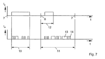
- Fig. 7 shows a variant of this principle.
- the modulation current I M has been extended to the maximum possible line length by adding the signal part 13.
- the power consumption of the laser diode is constant during a full revolution of the light beam deflection device 4, regardless of the shape of the modulation current I M , but has a higher value than in the variant according to FIG. 6.
- the effect of the variant according to FIG. 7 can be can be further optimized if the attached signal part 13 is shortened by a time portion 14 which compensates for the emitted light output during the exposure period 10 and the stabilization period 12. Since the thermal power loss is equal to the total power consumed minus the emitted light power, the thermal power loss is then constant during a full revolution of the light beam deflection device 4.
Landscapes
- Laser Beam Printer (AREA)
- Semiconductor Lasers (AREA)
- Electronic Switches (AREA)
- Exposure And Positioning Against Photoresist Photosensitive Materials (AREA)
Abstract
Description
- Fig. 1
- die Modulation einer Laserdiode in einem Strom-Leistungs-Diagramm,
- Fig. 2
- eine prinzipielle Darstellung einer Belichtungsvorrichtung vom Innentrommel-Typ im Schnittbild,
- Fig. 3
- Zeitdiagramme für den Basisstrom und den Modulationsstrom nach dem Stand der Technik,
- Fig. 4
- Zeitdiagramme für den Basisstrom und den Modulationsstrom gemäß der Erfindung,
- Fig. 5
- Zeitdiagramme für den Basisstrom und den Modulationsstrom während der Belichtungsvorbereitung und während der Belichtung,
- Fig. 6
- Zeitdiagramme für den Basisstrom und den Modulationsstrom nach einem weiteren Merkmal der Erfindung, und
- Fig. 7
- Zeitdiagramme für den Basisstrom und den Modulationsstrom für eine weitere Variante der Erfindung.
Claims (11)
- Verfahren zur thermischen Stabilisierung einer Laserdiode in einem Recorder, bei demmit einer Laserdiode ein Lichtstrahl (3) erzeugt wird,die Laserdiode durch die Überlagerung eines Basisstroms (IB) und eines Modulationsstroms (IM) moduliert wird, undAufzeichnungsmaterial (1) durch den modulierten Lichtstrahl (3) punktund zeilenweise belichtet wird, wobei zwischen den Belichtungszeiträumen (10), in denen jeweils eine Zeile belichtet wird, Rückführungszeiträume (11) vorhanden sind, in denen der Lichtstrahl (3) an den Anfang der nächsten Zeile geführt wird, dadurch gekennzeichnet, daß die Laserdiode innerhalb des Rückführungszeitraums (11) moduliert wird.
- Verfahren nach Anspruch 1, dadurch gekennzeichnet, daß die Laserdiode während eines Stabilisierungszeitraums (12) mit dem Basisstrom (IB) moduliert wird.
- Verfahren nach Anspruch 1 oder 2, dadurch gekennzeichnet, daß die Summe der Modulationszeiten mit dem Basisstrom (lB) während des Belichtungszeitraums (10) und während des Stabilisierungszeitraums (12) konstant ist.
- Verfahren nach Anspruch 3, dadurch gekennzeichnet, daß die Summe der Modulationszeiten mit dem Basisstrom (IB) während des Belichtungszeitraums (10) und während des Stabilisierungszeitraums (12) der maximalen belichtbaren Zeilenlänge entspricht.
- Verfahren nach einem der Ansprüche 1 bis 4, dadurch gekennzeichnet, daß die Laserdiode vor der Belichtung der ersten Zeile während des Stabilisierungszeitraums (12) mit dem Basisstrom (IB) moduliert wird.
- Verfahren nach einem der Ansprüche 1 bis 4, dadurch gekennzeichnet, daß bei einer Start/Stop-Betriebsart des Recorders die Laserdiode während einer Stopphase und einer Wiederanlaufphase während des Stabilisierungszeitraums (12) mit dem Basisstrom (IB) moduliert wird.
- Verfahren nach einem der Ansprüche 1 bis 4, dadurch gekennzeichnet, daß während des Rückführungszeitraums (11) die Laserdiode zusätzlich mit einem Modulationsstrom (IM) moduliert wird.
- Verfahren nach Anspruch 7, dadurch gekennzeichnet, daß der Modulationsstrom (IM) aus dem invertierten Bildsignal der vorangegangenen oder der nachfolgenden Zeile abgeleitet wird.
- Verfahren nach einem der Ansprüche 7 bis 8, dadurch gekennzeichnet, daß der Modulationsstrom (IM) um einen angefügten Signalteil (13) auf die maximal mögliche Zeilenlänge verlängert wird.
- Verfahren nach Anspruch 9, dadurch gekennzeichnet, daß der angefügte Signalteil (13) um einen Zeitanteil (14) gekürzt wird, der der abgestrahlten Lichtleistung der Laserdiode während des Belichtungszeitraums (10) und des Stabilisierungszeitraums (12) entspricht.
- Verfahren nach einem der Ansprüche 1 bis 10, dadurch gekennzeichnet, daß der Recorder ein Innentrommel-Recorder ist.
Applications Claiming Priority (2)
| Application Number | Priority Date | Filing Date | Title |
|---|---|---|---|
| DE10063707A DE10063707A1 (de) | 2000-12-20 | 2000-12-20 | Verfahren zur thermischen Stabilisierung einer Laserdiode in einem Recorder |
| DE10063707 | 2000-12-20 |
Publications (2)
| Publication Number | Publication Date |
|---|---|
| EP1220146A1 true EP1220146A1 (de) | 2002-07-03 |
| EP1220146B1 EP1220146B1 (de) | 2009-08-19 |
Family
ID=7668071
Family Applications (1)
| Application Number | Title | Priority Date | Filing Date |
|---|---|---|---|
| EP01126905A Expired - Lifetime EP1220146B1 (de) | 2000-12-20 | 2001-11-13 | Verfahren zur thermischen Stabilierung einer Laserdiode in einem Recorder |
Country Status (4)
| Country | Link |
|---|---|
| US (1) | US6734891B2 (de) |
| EP (1) | EP1220146B1 (de) |
| JP (1) | JP2002232071A (de) |
| DE (2) | DE10063707A1 (de) |
Families Citing this family (4)
| Publication number | Priority date | Publication date | Assignee | Title |
|---|---|---|---|---|
| US7199812B2 (en) * | 2002-10-28 | 2007-04-03 | Fujifilm Corporation | Laser marking method |
| JP5659476B2 (ja) * | 2009-09-25 | 2015-01-28 | ソニー株式会社 | 補正回路、駆動回路および発光装置 |
| JP5651983B2 (ja) * | 2010-03-31 | 2015-01-14 | ソニー株式会社 | 補正回路、駆動回路、発光装置、および電流パルス波形の補正方法 |
| JP5949411B2 (ja) * | 2012-10-04 | 2016-07-06 | ソニー株式会社 | 補正回路、駆動回路、発光装置、および電流パルス波形の補正方法 |
Citations (4)
| Publication number | Priority date | Publication date | Assignee | Title |
|---|---|---|---|---|
| US5309458A (en) | 1992-03-02 | 1994-05-03 | Ecrm Trust | Method and apparatus for stabilizing laser diode energy output |
| US5341156A (en) * | 1991-02-19 | 1994-08-23 | Minolta Camera Kabushiki Kaisha | Image forming apparatus of laser scanning type |
| US5495463A (en) | 1992-12-16 | 1996-02-27 | Matsushita Electric Industrial Co., Ltd. | Controller and control method of laser power for recording information in an optical record medium |
| EP0963016A2 (de) * | 1998-06-03 | 1999-12-08 | Hewlett-Packard Company | Regelung einen Diodenlaserleistungskompensator |
Family Cites Families (6)
| Publication number | Priority date | Publication date | Assignee | Title |
|---|---|---|---|---|
| JPS61165835A (ja) | 1985-01-17 | 1986-07-26 | Olympus Optical Co Ltd | 光出力安定化装置 |
| JPS63128371A (ja) | 1986-11-19 | 1988-05-31 | Canon Inc | 記録装置 |
| JPS6484446A (en) | 1987-09-28 | 1989-03-29 | Fuji Photo Film Co Ltd | Semiconductor laser light source device |
| JP3840794B2 (ja) * | 1998-04-13 | 2006-11-01 | 富士ゼロックス株式会社 | レーザ駆動装置 |
| US5999550A (en) * | 1999-01-08 | 1999-12-07 | Agfa Corporation | Automatic operating point calibration |
| DE19912463A1 (de) * | 1999-03-19 | 2000-09-28 | Sensor Line Ges Fuer Optoelekt | Verfahren zur Stabilisierung der optischen Ausgangsleistung von Leuchtdioden und Laserdioden |
-
2000
- 2000-12-20 DE DE10063707A patent/DE10063707A1/de not_active Withdrawn
-
2001
- 2001-11-13 EP EP01126905A patent/EP1220146B1/de not_active Expired - Lifetime
- 2001-11-13 DE DE50115050T patent/DE50115050D1/de not_active Expired - Lifetime
- 2001-12-18 JP JP2001385078A patent/JP2002232071A/ja active Pending
- 2001-12-20 US US10/034,050 patent/US6734891B2/en not_active Expired - Fee Related
Patent Citations (4)
| Publication number | Priority date | Publication date | Assignee | Title |
|---|---|---|---|---|
| US5341156A (en) * | 1991-02-19 | 1994-08-23 | Minolta Camera Kabushiki Kaisha | Image forming apparatus of laser scanning type |
| US5309458A (en) | 1992-03-02 | 1994-05-03 | Ecrm Trust | Method and apparatus for stabilizing laser diode energy output |
| US5495463A (en) | 1992-12-16 | 1996-02-27 | Matsushita Electric Industrial Co., Ltd. | Controller and control method of laser power for recording information in an optical record medium |
| EP0963016A2 (de) * | 1998-06-03 | 1999-12-08 | Hewlett-Packard Company | Regelung einen Diodenlaserleistungskompensator |
Also Published As
| Publication number | Publication date |
|---|---|
| US20020113858A1 (en) | 2002-08-22 |
| DE50115050D1 (de) | 2009-10-01 |
| US6734891B2 (en) | 2004-05-11 |
| JP2002232071A (ja) | 2002-08-16 |
| EP1220146B1 (de) | 2009-08-19 |
| DE10063707A1 (de) | 2002-07-04 |
Similar Documents
| Publication | Publication Date | Title |
|---|---|---|
| DE3751364T2 (de) | Präzisionspapiertransportsystem. | |
| DE69215024T2 (de) | Mikroadressierbarkeit durch überabgetastete Beleuchtung für optische Drucker od. dgl. mit fotoempfindlichen Aufzeichnungsmedia hoher Steilheit | |
| DE3926636C2 (de) | ||
| DE69330939T2 (de) | Verfahren und Gerät zur Störungsbeseitigung durch überabgetastete Beleuchtung für optische Drucker und ähnliche mit photoempfindlichem Aufzeichnungsmedium mit hohem Gamma und hoher Adressierbarkeit | |
| DE69413648T2 (de) | Elektronische Simulation zur Kompensation von Wärmeeffekten in Diodenlaser | |
| DE4115163B4 (de) | Bilderzeugungseinrichtung | |
| DE3534338A1 (de) | Elektrofotografischer drucker mit einer belichtungsenergie/korrektureinrichtung fuer den optischen zeichengenerator | |
| DE3874146T2 (de) | Stabilisierung der leistung des ausgangs eines ein bild bildenden lasers, der aus einer diode besteht. | |
| DE69732939T2 (de) | Diodengepumptes Lasersystem und Verfahren | |
| DE10031915A1 (de) | Kompakte Mehrstrahllaserlichtquelle und Interleafrasterscanlinien-Verfahren zur Belichtung von Druckplatten | |
| DE3140081A1 (de) | Laserstrahldrucker | |
| DE19953144A1 (de) | Verfahren zum Verlängern der Belichtungszeit in Laserscannern | |
| DE69222604T2 (de) | Aufzeichnungsabtaster mit Steuerung der Punktposition in der Nebenabtastrichtung | |
| DE69822093T2 (de) | Methode und Gerät zum Belichten mittels Laserdioden mit Korrektur von Schwankungen der Ausgangsleistung | |
| DE69808183T2 (de) | Linsenloses Drucksystem mit einem Lichtstabdruckkopf | |
| EP1220146B1 (de) | Verfahren zur thermischen Stabilierung einer Laserdiode in einem Recorder | |
| DE60317865T2 (de) | Treiberschaltung für einen Lichtemitter | |
| DE69326646T2 (de) | Verfahren und Vorrichtung zur Verbesserung von Auflösung und Kontrast durch eine überabgetastete Beleuchtung mit Intensitätssteuerung in einem zwei-dimensionalen mikro- adressierbaren Drucker | |
| DE102013202091A1 (de) | Bilderzeugungsgerät zur mehrmaligen Ausführung einer Belichtung | |
| DE3903586C2 (de) | Laserdrucker | |
| DE19707003C2 (de) | Beschriftungslasersystem und Verfahren zur Beschriftung | |
| DE60025565T2 (de) | Optische Abtastvorrichtung und diese verwendendes Farbbilderzeugungsgerät | |
| DE68914366T2 (de) | Abtastvorrichtung mit optischem Strahl. | |
| DE68919027T2 (de) | Verfahren zur Verminderung des durchschnittlichen Datenflusses in einer Laserregistriervorrichtung mit drehbarem Spiegel. | |
| EP1580980B1 (de) | Verfahren und Druckplatte zum Abgleichen der Belichtungsköpfe in einem Belichter für Druckvorlagen |
Legal Events
| Date | Code | Title | Description |
|---|---|---|---|
| PUAI | Public reference made under article 153(3) epc to a published international application that has entered the european phase |
Free format text: ORIGINAL CODE: 0009012 |
|
| AK | Designated contracting states |
Kind code of ref document: A1 Designated state(s): AT BE CH CY DE DK ES FI FR GB GR IE IT LI LU MC NL PT SE TR |
|
| AX | Request for extension of the european patent |
Free format text: AL;LT;LV;MK;RO;SI |
|
| 17P | Request for examination filed |
Effective date: 20030103 |
|
| AKX | Designation fees paid |
Designated state(s): DE FR GB |
|
| 17Q | First examination report despatched |
Effective date: 20061222 |
|
| GRAP | Despatch of communication of intention to grant a patent |
Free format text: ORIGINAL CODE: EPIDOSNIGR1 |
|
| GRAS | Grant fee paid |
Free format text: ORIGINAL CODE: EPIDOSNIGR3 |
|
| GRAA | (expected) grant |
Free format text: ORIGINAL CODE: 0009210 |
|
| AK | Designated contracting states |
Kind code of ref document: B1 Designated state(s): DE FR GB |
|
| REG | Reference to a national code |
Ref country code: GB Ref legal event code: FG4D Free format text: NOT ENGLISH |
|
| REF | Corresponds to: |
Ref document number: 50115050 Country of ref document: DE Date of ref document: 20091001 Kind code of ref document: P |
|
| PLBE | No opposition filed within time limit |
Free format text: ORIGINAL CODE: 0009261 |
|
| STAA | Information on the status of an ep patent application or granted ep patent |
Free format text: STATUS: NO OPPOSITION FILED WITHIN TIME LIMIT |
|
| 26N | No opposition filed |
Effective date: 20100520 |
|
| PGFP | Annual fee paid to national office [announced via postgrant information from national office to epo] |
Ref country code: DE Payment date: 20121130 Year of fee payment: 12 |
|
| PGFP | Annual fee paid to national office [announced via postgrant information from national office to epo] |
Ref country code: GB Payment date: 20121126 Year of fee payment: 12 |
|
| PGFP | Annual fee paid to national office [announced via postgrant information from national office to epo] |
Ref country code: FR Payment date: 20121214 Year of fee payment: 12 |
|
| GBPC | Gb: european patent ceased through non-payment of renewal fee |
Effective date: 20131113 |
|
| REG | Reference to a national code |
Ref country code: FR Ref legal event code: ST Effective date: 20140731 |
|
| PG25 | Lapsed in a contracting state [announced via postgrant information from national office to epo] |
Ref country code: DE Free format text: LAPSE BECAUSE OF NON-PAYMENT OF DUE FEES Effective date: 20140603 |
|
| REG | Reference to a national code |
Ref country code: DE Ref legal event code: R119 Ref document number: 50115050 Country of ref document: DE Effective date: 20140603 |
|
| PG25 | Lapsed in a contracting state [announced via postgrant information from national office to epo] |
Ref country code: FR Free format text: LAPSE BECAUSE OF NON-PAYMENT OF DUE FEES Effective date: 20131202 Ref country code: GB Free format text: LAPSE BECAUSE OF NON-PAYMENT OF DUE FEES Effective date: 20131113 |