EP1219152A1 - Transportwagen eines Schneidewerks - Google Patents
Transportwagen eines Schneidewerks Download PDFInfo
- Publication number
- EP1219152A1 EP1219152A1 EP01129910A EP01129910A EP1219152A1 EP 1219152 A1 EP1219152 A1 EP 1219152A1 EP 01129910 A EP01129910 A EP 01129910A EP 01129910 A EP01129910 A EP 01129910A EP 1219152 A1 EP1219152 A1 EP 1219152A1
- Authority
- EP
- European Patent Office
- Prior art keywords
- axis
- storage element
- transport trolley
- cutting unit
- pivotable
- Prior art date
- Legal status (The legal status is an assumption and is not a legal conclusion. Google has not performed a legal analysis and makes no representation as to the accuracy of the status listed.)
- Granted
Links
Images




Classifications
-
- A—HUMAN NECESSITIES
- A01—AGRICULTURE; FORESTRY; ANIMAL HUSBANDRY; HUNTING; TRAPPING; FISHING
- A01D—HARVESTING; MOWING
- A01D75/00—Accessories for harvesters or mowers
- A01D75/002—Carriers for the transport of harvesters or mowers
Definitions
- So-called rapeseed headers are used to harvest rapeseed with a combine harvester known on normal cutterbars can be attached and a cutting table extension with driven cutting blades that the cutting unit in the Direction of advance of the combine is extended, as well as on both sides of the cutting table have arranged side cutting units.
- the Cutting table extension and the side cutters are expedient to the rape, which is a coherent shrubbery forms to cut up.
- rapeseed headers are to be used, they are used in usually attached to the cutting unit and together with the Cutting unit transported to the field to be harvested on a wagon.
- a disadvantage is that it is not possible the cutting unit by attaching or removing the front cutting unit to switch to different crops without to return to a firm, level surface around the rape header when attaching and detaching it remedy.
- IT 1 223 703 A discloses a transport trolley for harvesting headers, which is a single shelf for a header having.
- the storage area is changed by a hydraulic cylinder a horizontal axis running parallel to the direction of travel between an approximately vertical transport position and an approximately horizontal position in which a header is removed or is discarded, pivoted.
- This car forms a fixed one Storage area, but the operator would have to do this on the combine attached cutting unit exactly in the front cutting unit thread what is not unproblematic.
- a Cutting unit transport carriage described the first Storage area for a cutting unit and a second storage area for a header, especially for rape harvest, having.
- the two shelves are relative to each other movable, in particular displaceable and / or pivotable in order bring the front header to a header or deduct from it.
- the problem underlying the invention is seen in an improved trolley for a cutting unit and a To create front cutter, in which the attachment of the Front header on the header is facilitated.
- the invention relates to a trolley with a Chassis on which a storage element can be pivoted about an axis is supported.
- a cutting unit can be placed on the storage element and / or a front cutter can be stored.
- the axle supporting or supporting Element itself is also movable, namely by one Swiveling axis can be given away. This allows the position of the axis be relocated to the chassis.
- the storage element receives two degrees of freedom, namely the known rotation about the axis and the additional pivoting movement of the axis according to the invention.
- a Panning or rotating movement is usually easier realize as a displacement movement, as in DE 199 31 281 A is described.
- the element holding the axis in the manner to design a spherical head which is a pivoting of the storage element around two mutually orthogonal axes would. So it could be between a space-saving rest position, in which it is oriented downwards and along the direction of travel and a transport position in which it is approximately is arranged horizontally and transversely to the direction of travel and a Cutter can accommodate, be relocatable.
- the element supporting the axis by one of the Axis spaced pivot axis is pivotable. The result is that the movement about the pivot axis is the position of the Axis - and thus the height of the horizontal swivel axis Axis - defined.
- the rotation defines the horizontal axis of the storage element about the axis, the inclination of the storage element.
- the axis and the pivot axis of the element run preferably in parallel.
- the storage element can thus be any Take positions, for example, it can be horizontal oriented and lowered down or opposite the Horizontal be inclined and raised.
- the element holding the axis is preferably a first one Drive assigned, preferably a hydraulic cylinder that the Element moved about the pivot axis. He can turn a shaft to which the element is attached, and its longitudinal axis with the Swivel axis coincides. Several elements can be on the shaft be attached, each holding an axis on which a Storage element is rotatably mounted.
- a second drive can rotate the storage element be assigned to the axis.
- Hydraulic cylinders into consideration, though - as with the first Drive - any other drive devices can be used are, such as B. Hydraulic, combustion and electric motors.
- the trolley has in addition to the above described, pivotable storage element yet another Storage element on that for receiving a cutting unit or a header can serve. It would be conceivable that to make more storage element movable, in particular how the swiveling storage element. But it is preferred that further storage element rigid or optionally with a or several springs or similar, elastic elements flexible to be attached to the chassis of the trolley. A drive to move the further storage element is unnecessary.
- the cutting unit on the other storage element put down and the front header on the movable Storage element.
- the other storage element and the movable storage element expediently in the same plane, preferably for easier storage of the cutting unit a combine harvester slightly inclined to the horizontal runs. Due to the mobility of the movable shelf element there is a possibility after loosening a mechanical Connection between the cutting unit and the front cutting unit Front header by rotating the storage element around the axis separate from the cutting unit, being a relatively small one Angle of rotation can be sufficient for separation, and then by a pivoting movement of the position defining the axis Elements around the pivot axis in a transport position lower down. The rotary movement around the axis then defines the inclination of the movable storage element. It can do the same Storage element can be brought back up to the Attach the front cutting unit to the cutting unit.
- the transport carriage 10 shown in Figure 1 consists in its basic structure from one in the direction of travel extending longitudinal beam 12, under which there is a cross to Longitudinal beam 12 extending cross member 14 extends at the Each ends with a rubber tire 16 with approximately horizontal, attached to the cross member 14 extending axis of rotation is.
- the longitudinal beam 12, the cross beam 14 and the wheels 16 form a chassis of the transport carriage 10.
- a storage element 18 is rigidly attached from an angle at an angle of about 30 ° upwards extending first beam 20 and one at the lower end of the first carrier 20 attached, at right angles to it upwards extending angle 22 is constructed.
- a cutter 24 for the in Figure 1 Grain harvest filed.
- the cutter 24 is on the first Carrier 20 and the angle 22 filed, the latter prevents the cutting unit 24 from the carrier 20 down slip.
- To support the cutting unit 24 are two Storage elements 18 present in the longitudinal direction of the The longitudinal beam 12 are spaced apart from one another, as in FIG. 5 is recognizable.
- a combine harvester can move from left to right Drive the trolley 10 up and pick up the cutting unit 24 or file.
- the longitudinal beam 12 also supports two in the longitudinal direction of the Longitudinal beam 12 spaced, movable storage elements 26, which each run parallel to the first carrier 20 have second carrier 28.
- the second carrier 28 provides one Extension of the first carrier 20, thus runs in one Plane and coaxial with it.
- an attachment cutter 30 is stored in FIG.
- the Front cutter 30 and cutter 24 are on the in Figure 1 shown trolley 10 relative to each other positioned that by attaching or detaching Fasteners, such as screws, bolts or split pins, can be attached to or detached from one another. are the fasteners attached, a combine harvester the side shown in Figure 1 on the left of the trolley 10 drive up and the cutting unit 24 with the attached Take up front cutter 30.
- the movable storage elements 26 are not on the side member 12 as the storage elements 18 rigidly attached, but pivotable.
- the second carrier 28 with a at its lower, the rigid storage element 18 adjacent Rigidly attached end, angled 90 ° downwards Equipped angle element 32 which is pivotable about an axis 42 is connected to an angle lever that consists of two rigid over a rotatable shaft 50 interconnected lever arms 34, 36 consists.
- the first lever arm 34 is thus one end to the Axis 42 running parallel to the longitudinal axis of the longitudinal beam 12 pivotally attached to the angle member 32, and other end with connected to the shaft 50.
- the shaft 50 is as in Figure 5 recognizable, connected to the second lever arm 36, the is arched.
- the shaft 50 runs parallel to the Longitudinal axis of the longitudinal beam 12, and is on its top arranged rotatably.
- the outer end of the second Lever arm 36 is parallel to the longitudinal direction of the Longitudinal beam 12 axis 52 pivotable with the piston of a first hydraulic cylinder 38.
- the housing of the first hydraulic cylinder 38 is parallel to the longitudinal axis of the longitudinal beam 12 extending axis 54 pivotable on the Top of the cross member 14 is articulated and is about the center of the trolley 10.
- the shaft 50 moves the two Lever arms 34, each having an axis 42 with one of the Carrier 28 are connected.
- a connecting element 40 is rigid on the angle element 32 attached, which extends from the lower end of the angle element 32nd extends parallel to the angle element 32 upwards and almost ends immediately below the first carrier 20. The right The long side of the connecting element 40 is thus on the left Long side of the angle element 32.
- On the connecting element 40 is pivotable about an axis 44, which is also parallel to Longitudinal axis of the longitudinal beam 12 runs, the piston one second hydraulic cylinder 46 articulated.
- the case of the second Hydraulic cylinder 46 is connected to a pivot bearing 48 axis running parallel to the longitudinal axis of the longitudinal beam 12 48 articulated on the first support 20. It would be conceivable that Angle element 32 and the connecting element 40 in one piece shape.
- the connecting element 40 could also be between extend two angle elements 32, each a second Carriers 28 are assigned to two movable storage elements 26 to be able to move with only a second hydraulic cylinder 46. In in the present embodiment, however, each angular element is 32nd a second hydraulic cylinder 46 is assigned, as in FIG. 5 is recognizable.
- the trolley 10 is provided with a towing eye 56 with which it can be attached to a combine harvester or another towing vehicle is.
- the first hydraulic cylinder 38 and the second hydraulic cylinder 46 are double-acting and are operated by the hydraulic system operated by a combine. But it would also be conceivable that To provide trolley 10 with its own hydraulic system.
- the hydraulic cylinders 38, 46 are controlled by a suitable control device preferably as in the figures 1 to 4 is indicated:
- the second hydraulic cylinder 46 becomes such controlled that its piston extends, as in FIG. 2 recognizable.
- the piston chamber of the second Hydraulic cylinder 46 pressurized and / or Hydraulic fluid let out of the piston rod space become.
- the first hydraulic cylinder 38 is not moved.
- the result is that the movable storage element 26 with the Front cutter 30 about the axis 42 by about 5 ° in Turns clockwise downward so that the Front cutter 30 slightly away from cutter 24 emotional.
- the second hydraulic cylinder 46 rotates its attachment points, axes 44 and 48. This Pivotal movement of the movable storage element 26 can Separating the front cutter 30 from the cutter 24 be more advantageous than a displacement movement, and is constructively easier to implement.
- the first hydraulic cylinder 46 controlled in such a way that its piston extends, as in FIG. 3 recognizable.
- the piston chamber of the first hydraulic cylinder can do this 46 pressurized and / or hydraulic fluid the piston rod space can be let out.
- the axis 42 continuously lowers as the first Hydraulic cylinder 38 consisting of the lever arms 34, 36 Allows the angle lever to rotate clockwise downwards.
- the second hydraulic cylinder 46 also becomes such controlled that its piston extends. This turns it second storage element 26 clockwise around the axis 42. In the the position shown in Figure 3 is the movable one Storage element 26 has been rotated into a horizontal position.
- the two hydraulic cylinders 38, 46 can be extended done simultaneously or sequentially, or they will each extended one step at a time.
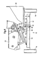
- FIGS. 6 to 8 show a second embodiment of a Transport vehicle 10 according to the invention shown, wherein matching elements are provided with reference numerals that correspond to those of the first embodiment.
- the second is in essentially identical to the first embodiment; she points however, the following differences from the first embodiment Figure 1 to 5 on:
- the first hydraulic cylinder 38 is at the bottom of the Cross member 14 hinged to the axis 54. His piston rod is on the axis 52 with a lever arm 36 of the two Lever arms 34, 36 constructed angle lever connected, the Lever arm 36 is connected to the rotatable shaft 50 on which the Lever arms 34 are attached.
- the piston of the first Hydraulic cylinder 38 is shown in FIG Position in which the movable storage element 26 with the first Storage element 18, which is also rigid with the side member 12 and / or the cross member 14 is connected in one plane, extended. It can thus be a single-acting embodiment Find use because to lower the movable Storage element 26 only hydraulic fluid from the piston chamber drain and fill in to lift.
- the task of first hydraulic cylinder 38 is the position of the axis 42 by rotating the shaft 50 and the lever arm 34.
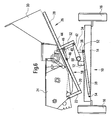
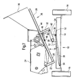
- FIGS. 7 and 8 the manner of movement of the movable storage element 26 of the second Embodiment of the mode of movement of the first embodiment corresponds to that shown in FIGS. 1 to 3. Also here the front cutter 30 is opposite the cutter 24 first tilted down, and then into a lowered, about horizontal position spent. The piston of the first Hydraulic cylinder 38, however, not extended, but moved in. The lifting of the movable storage element 26 is done in reverse.
- second hydraulic cylinder 46 In the second embodiment as well, only one would be conceivable second hydraulic cylinder 46 to use, with both movable storage elements 26 is coupled. everyone can too A first hydraulic cylinder 38 can be assigned to the storage element. In any case, the two storage elements 26 are assigned Hydraulic cylinder controlled synchronously, so that both Storage elements 26 are moved synchronously.
Landscapes
- Life Sciences & Earth Sciences (AREA)
- Environmental Sciences (AREA)
- Handcart (AREA)
- Harvester Elements (AREA)
- Harvesting Machines For Specific Crops (AREA)
Abstract
Description
- Fig. 1
- eine rückwärtige Ansicht eines erfindungsgemäßen Transportwagens, bei der sich ein Ablageelement für ein Vorsatzschneidwerk in einer Stellung befindet, in der ein Vorsatzschneidwerk an ein Schneidwerk anbringbar oder davon abnehmbar ist;
- Fig. 2
- den Transportwagen der Figur 1, wobei das Ablageelement des Vorsatzschneidwerks geringfügig nach unten geschwenkt ist;
- Fig. 3
- den Transportwagen der Figur 1, wobei das Ablageelement des Vorsatzschneidwerks nach unten abgesenkt und in eine horizontale Lage gedreht ist;
- Fig. 4
- den Transportwagen der Figur 1, wobei das Ablageelement des Vorsatzschneidwerks nach unten abgesenkt und nach außen bewegt ist;
- Fig. 5
- eine perspektivische Ansicht des Transportwagens der Figuren 1 bis 4;
- Fig. 6
- eine rückwärtige Ansicht einer zweiten Ausführungsform eines Transportwagens, bei der das Ablageelement für ein Vorsatzschneidwerk sich in einer Stellung befindet, in der ein Vorsatzschneidwerk an ein Schneidwerk anbringbar oder davon abnehmbar ist;
- Fig. 7
- den Transportwagen der Figur 6, wobei das Ablageelement des Vorsatzschneidwerks geringfügig nach unten gekippt ist; und
- Fig. 8
- den Transportwagen der Figur 6, wobei das Ablageelement des Vorsatzschneidwerks nach unten abgesenkt ist.
Claims (12)
- Transportwagen (10) mit einem Fahrgestell, an dem ein Ablageelement (26) zur Aufnahme eines Schneidwerks (24) und/oder eines Vorsatzschneidwerks (30) angebracht ist, wobei das Ablageelement (26) um eine Achse (42) verschwenkbar am Fahrgestell gelagert ist, dadurch gekennzeichnet, dass die Position der Achse (42) gegenüber dem Fahrgestell durch Verschwenken eines die Achse (42) halternden Elements veränderbar ist.
- Transportwagen (10) nach Anspruch 1, dadurch gekennzeichnet, dass das die Achse (42) halternde Element um eine Schwenkachse verschwenkbar ist, die von der Achse (42) beabstandet ist.
- Transportwagen (10) nach Anspruch 2, dadurch gekennzeichnet, dass die Achse (42) und die Schwenkachse des die Achse (42) halternden Elements parallel zueinander und vorzugsweise parallel zur Fahrtrichtung verlaufen.
- Transportwagen (10) nach einem der Ansprüche 1 bis 3, gekennzeichnet durch einen ersten Antrieb, insbesondere einen ersten Hydraulikzylinder (38), mit dem das die Achse (42) halternde Element um die Schwenkachse verschwenkbar ist.
- Transportwagen (10) nach Anspruch 4, dadurch gekennzeichnet, dass der erste Antrieb zur Drehung einer Welle (50) eingerichtet ist, an der das die Achse (42) halternde Element angebracht ist, wobei die Längsachse der Welle (50) und die Schwenkachse übereinstimmen.
- Transportwagen (10) nach einem der Ansprüche 1 bis 5, gekennzeichnet durch einen zweiten Antrieb, insbesondere einen zweiten Hydraulikzylinder (46), mit dem das Ablageelement (26) um die Achse (42) schwenkbar ist.
- Transportwagen (10) nach einem der Ansprüche 1 bis 6, dadurch gekennzeichnet, dass am Fahrgestell zusätzlich ein weiteres Ablageelement (18) befestigt ist.
- Transportwagen (10) nach Anspruch 7, dadurch gekennzeichnet, dass das weitere Ablageelement (18) starr oder federnd am Fahrgestell befestigt ist.
- Transportwagen (10) nach Anspruch 7 oder 8, dadurch gekennzeichnet, dass auf dem schwenkbaren Ablageelement (26) ein Vorsatzschneidwerk (30) ablegbar und/oder abgelegt ist, und dass auf dem weiteren Ablageelement (18) ein Schneidwerk (24) ablegbar und/oder abgelegt ist.
- Transportwagen nach Anspruch 9, dadurch gekennzeichnet, dass das schwenkbare Ablageelement (26) und das weitere Ablageelement (18) derart angeordnet sind, dass ein auf dem schwenkbaren Ablageelement (26) angeordnetes Vorsatzschneidwerk (30) in Richtung auf ein Schneidwerk (24), das sich auf dem weiteren Ablageelement (18) befindet, zu bzw. davon fort bewegbar und daran fixierbar bzw. davon trennbar ist.
- Transportwagen nach einem der Ansprüche 1 bis 10, dadurch gekennzeichnet, dass das schwenkbare Ablageelement (26) zwischen einer Stellung, in der es horizontal orientiert ist und einer Stellung, in der es geneigt ist, bewegbar ist, wobei es in der geneigten Stellung höher als in der horizontalen Stellung ist.
- Transportwagen nach einem der Ansprüche 7 bis 11, dadurch gekennzeichnet, dass das schwenkbare Ablageelement (26) in der geneigten Stellung mit dem weiteren Ablageelement (18) in derselben Ebene liegt.
Applications Claiming Priority (2)
| Application Number | Priority Date | Filing Date | Title |
|---|---|---|---|
| DE10064961 | 2000-12-23 | ||
| DE10064961A DE10064961A1 (de) | 2000-12-23 | 2000-12-23 | Transportwagen |
Publications (2)
| Publication Number | Publication Date |
|---|---|
| EP1219152A1 true EP1219152A1 (de) | 2002-07-03 |
| EP1219152B1 EP1219152B1 (de) | 2005-03-23 |
Family
ID=7668942
Family Applications (1)
| Application Number | Title | Priority Date | Filing Date |
|---|---|---|---|
| EP01129910A Expired - Lifetime EP1219152B1 (de) | 2000-12-23 | 2001-12-15 | Transportwagen eines Schneidewerks |
Country Status (4)
| Country | Link |
|---|---|
| EP (1) | EP1219152B1 (de) |
| AT (1) | ATE291345T1 (de) |
| DE (2) | DE10064961A1 (de) |
| ES (1) | ES2240319T3 (de) |
Cited By (2)
| Publication number | Priority date | Publication date | Assignee | Title |
|---|---|---|---|---|
| WO2013135752A1 (en) | 2012-03-13 | 2013-09-19 | Cnh Belgium N.V. | Loading and transport apparatus for agricultural cutting devices |
| DE102013107194A1 (de) | 2013-07-08 | 2015-01-08 | Esm Ennepetaler Schneid- Und Mähtechnik Gmbh & Co. Kg | Verlade- und Transportvorrichtung für landwirtschaftliche Schneidwerke |
Families Citing this family (2)
| Publication number | Priority date | Publication date | Assignee | Title |
|---|---|---|---|---|
| DE102006041387B3 (de) * | 2006-08-29 | 2007-12-20 | Schmücking, Jörg | Prüfanordnung für ein Mähdrescherschneidwerk |
| DE102007046184A1 (de) * | 2007-09-26 | 2009-04-02 | Claas Selbstfahrende Erntemaschinen Gmbh | Schneidwerkswagen |
Citations (7)
| Publication number | Priority date | Publication date | Assignee | Title |
|---|---|---|---|---|
| US4371299A (en) * | 1980-07-24 | 1983-02-01 | Deere & Company | Trailer frame |
| US4714273A (en) * | 1986-01-06 | 1987-12-22 | Kejr Melvin P | Vehicle for transporting elongated objects |
| US4770577A (en) * | 1985-05-03 | 1988-09-13 | Farris Gary C | Transport vehicle for combine harvester headers |
| US4834598A (en) * | 1987-06-22 | 1989-05-30 | Bruns Wesley W | Combine head carrier for transport vehicle |
| IT1223703B (it) * | 1988-07-18 | 1990-09-29 | Fiatgeotech | Carrello per il trasporto di organi di macchine agricole particolarmente piattaforme di taglio di macchine mietitrebbiatrici |
| US5529447A (en) * | 1994-11-28 | 1996-06-25 | May-Wes Manufacturing, Inc. | Combined header transport vehicle |
| EP1066744A1 (de) * | 1999-07-07 | 2001-01-10 | Deere & Company | Wagen zum Transport eines Schneidwerks |
Family Cites Families (3)
| Publication number | Priority date | Publication date | Assignee | Title |
|---|---|---|---|---|
| US3413014A (en) * | 1966-09-26 | 1968-11-26 | Newton Mfg Co | Transportation means for combine header or the like |
| CS156847B1 (de) * | 1972-12-01 | 1974-08-23 | ||
| DD301470A7 (de) * | 1988-11-04 | 1993-02-11 | Saechsische Maehdrescherwerke | Transportwagen zum transport von schneidwerken mit zusatzausruestung |
-
2000
- 2000-12-23 DE DE10064961A patent/DE10064961A1/de not_active Withdrawn
-
2001
- 2001-12-15 EP EP01129910A patent/EP1219152B1/de not_active Expired - Lifetime
- 2001-12-15 ES ES01129910T patent/ES2240319T3/es not_active Expired - Lifetime
- 2001-12-15 DE DE50105682T patent/DE50105682D1/de not_active Expired - Fee Related
- 2001-12-15 AT AT01129910T patent/ATE291345T1/de not_active IP Right Cessation
Patent Citations (7)
| Publication number | Priority date | Publication date | Assignee | Title |
|---|---|---|---|---|
| US4371299A (en) * | 1980-07-24 | 1983-02-01 | Deere & Company | Trailer frame |
| US4770577A (en) * | 1985-05-03 | 1988-09-13 | Farris Gary C | Transport vehicle for combine harvester headers |
| US4714273A (en) * | 1986-01-06 | 1987-12-22 | Kejr Melvin P | Vehicle for transporting elongated objects |
| US4834598A (en) * | 1987-06-22 | 1989-05-30 | Bruns Wesley W | Combine head carrier for transport vehicle |
| IT1223703B (it) * | 1988-07-18 | 1990-09-29 | Fiatgeotech | Carrello per il trasporto di organi di macchine agricole particolarmente piattaforme di taglio di macchine mietitrebbiatrici |
| US5529447A (en) * | 1994-11-28 | 1996-06-25 | May-Wes Manufacturing, Inc. | Combined header transport vehicle |
| EP1066744A1 (de) * | 1999-07-07 | 2001-01-10 | Deere & Company | Wagen zum Transport eines Schneidwerks |
Cited By (7)
| Publication number | Priority date | Publication date | Assignee | Title |
|---|---|---|---|---|
| WO2013135752A1 (en) | 2012-03-13 | 2013-09-19 | Cnh Belgium N.V. | Loading and transport apparatus for agricultural cutting devices |
| DE102012102084A1 (de) | 2012-03-13 | 2013-09-19 | Cnh Belgium Nv | Verlade- und Transportvorrichtung für landwirtschaftliche Schneidwerke |
| DE102012102084B4 (de) * | 2012-03-13 | 2014-05-15 | Cnh Belgium Nv | Verlade- und Transportvorrichtung für landwirtschaftliche Schneidwerke |
| US20150050108A1 (en) * | 2012-03-13 | 2015-02-19 | Cnh Industrial America Llc | Loading and Transport Apparatus for Agricultural Cutting Devices |
| RU2566191C1 (ru) * | 2012-03-13 | 2015-10-20 | СиЭнЭйч ИНДАСТРИАЛ БЕЛДЖИУМ НВ | Погрузочное и транспортировочное устройство для сельскохозяйственных режущих устройств |
| US9596807B2 (en) * | 2012-03-13 | 2017-03-21 | Cnh Industrial America Llc | Loading and transport apparatus for agricultural cutting devices |
| DE102013107194A1 (de) | 2013-07-08 | 2015-01-08 | Esm Ennepetaler Schneid- Und Mähtechnik Gmbh & Co. Kg | Verlade- und Transportvorrichtung für landwirtschaftliche Schneidwerke |
Also Published As
| Publication number | Publication date |
|---|---|
| DE10064961A1 (de) | 2002-06-27 |
| DE50105682D1 (de) | 2005-04-28 |
| ATE291345T1 (de) | 2005-04-15 |
| ES2240319T3 (es) | 2005-10-16 |
| EP1219152B1 (de) | 2005-03-23 |
Similar Documents
| Publication | Publication Date | Title |
|---|---|---|
| EP2067397B1 (de) | Erntevorsatz für landwirtschaftliche Erntemaschinen zum Aufnehmen und Weiterfördern von Halmfrüchten | |
| EP1709858B1 (de) | Erntevorsatz für landwirtschaftliche Erntemaschinen | |
| EP3090617B1 (de) | Fahrbare erntemaschine und verfahren zum ernten von pflanzenteilen | |
| DE102013001651B4 (de) | Schutzvorrichtung eines Mäh- und Einzugswerks einer Erntemaschine und Erntemaschine mit einer solchen Schutzvorrichtung | |
| EP1362504A1 (de) | Maschine zum Mähen von stängelartigem Erntegut | |
| EP1287732A1 (de) | Erntevorsatz | |
| DE102008042392B4 (de) | Erntevorsatz für landwirtschaftliche Erntemaschinen | |
| BE1028095A1 (de) | Erntevorsatz mit Mulchgeräten zur Bearbeitung von auf einem Feld stehenden Pflanzenstümpfen mit verbessertem Schutz gegen abgeschleuderte Steine | |
| EP1023825B1 (de) | Aufhängung und Arbeitsgerät bzw. Fahrzeug | |
| EP1219152B1 (de) | Transportwagen eines Schneidewerks | |
| DE102007035796B4 (de) | Vorrichtung zur Arretierung eines Wagens zur Abstützung eines Erntevorsatzes bei einer Straßenfahrt an dem Erntevorsatz | |
| DE1482111A1 (de) | Anbauvorrichtung fuer den Seitenanbau von landwirtschaftlichen Geraeten an einen Ackerschlepper | |
| DE2058255A1 (de) | Mit Abweisern am Schneidwerktisch versehener Maehdrescher | |
| DE102004031514B3 (de) | Querpendeleinrichtung für Vorsatzgeräte an Landmaschinen | |
| DE102013209740B4 (de) | Landwirtschaftliches Arbeitsgerät | |
| EP0114295B1 (de) | An einen Schlepper anbaubare Erntebergungsvorrichtung | |
| EP1066744B1 (de) | Wagen zum Transport eines Schneidwerks | |
| DE3937124A1 (de) | Mit profilbandlaufwerken arbeitendes mehrzweckfahrzeug | |
| DE1482095B2 (de) | Maehmaschine | |
| EP1829444B1 (de) | Kreiselschwader | |
| DE2046552A1 (de) | Schlepper mit verschiebbarem Fahrer sitz | |
| DE19933779A1 (de) | Selbstfahrende landwirtschaftliche Erntemaschine | |
| BE1031908B1 (de) | Erntevorsatz für eine selbstfahrende Erntemaschine | |
| DE102006030508B4 (de) | Anordnung zur pendelnden Aufhängung eines Erntevorsatzes an einer Erntemaschine | |
| DE102005004212B4 (de) | Erntevorsatz für landwirtschaftliche Erntemaschine |
Legal Events
| Date | Code | Title | Description |
|---|---|---|---|
| PUAI | Public reference made under article 153(3) epc to a published international application that has entered the european phase |
Free format text: ORIGINAL CODE: 0009012 |
|
| AK | Designated contracting states |
Kind code of ref document: A1 Designated state(s): AT BE CH CY DE DK ES FI FR GB GR IE IT LI LU MC NL PT SE TR |
|
| AX | Request for extension of the european patent |
Free format text: AL;LT;LV;MK;RO;SI |
|
| 17P | Request for examination filed |
Effective date: 20030103 |
|
| AKX | Designation fees paid |
Designated state(s): AT BE CH CY DE DK ES FI FR GB GR IE IT LI LU MC NL PT SE TR |
|
| GRAP | Despatch of communication of intention to grant a patent |
Free format text: ORIGINAL CODE: EPIDOSNIGR1 |
|
| GRAS | Grant fee paid |
Free format text: ORIGINAL CODE: EPIDOSNIGR3 |
|
| GRAA | (expected) grant |
Free format text: ORIGINAL CODE: 0009210 |
|
| AK | Designated contracting states |
Kind code of ref document: B1 Designated state(s): AT BE CH CY DE DK ES FI FR GB GR IE IT LI LU MC NL PT SE TR |
|
| PG25 | Lapsed in a contracting state [announced via postgrant information from national office to epo] |
Ref country code: TR Free format text: LAPSE BECAUSE OF FAILURE TO SUBMIT A TRANSLATION OF THE DESCRIPTION OR TO PAY THE FEE WITHIN THE PRESCRIBED TIME-LIMIT Effective date: 20050323 Ref country code: NL Free format text: LAPSE BECAUSE OF FAILURE TO SUBMIT A TRANSLATION OF THE DESCRIPTION OR TO PAY THE FEE WITHIN THE PRESCRIBED TIME-LIMIT Effective date: 20050323 Ref country code: IT Free format text: LAPSE BECAUSE OF FAILURE TO SUBMIT A TRANSLATION OF THE DESCRIPTION OR TO PAY THE FEE WITHIN THE PRE;WARNING: LAPSES OF ITALIAN PATENTS WITH EFFECTIVE DATE BEFORE 2007 MAY HAVE OCCURRED AT ANY TIME BEFORE 2007. THE CORRECT EFFECTIVE DATE MAY BE DIFFERENT FROM THE ONE RECORDED.SCRIBED TIME-LIMIT Effective date: 20050323 Ref country code: IE Free format text: LAPSE BECAUSE OF FAILURE TO SUBMIT A TRANSLATION OF THE DESCRIPTION OR TO PAY THE FEE WITHIN THE PRESCRIBED TIME-LIMIT Effective date: 20050323 Ref country code: GB Free format text: LAPSE BECAUSE OF FAILURE TO SUBMIT A TRANSLATION OF THE DESCRIPTION OR TO PAY THE FEE WITHIN THE PRESCRIBED TIME-LIMIT Effective date: 20050323 Ref country code: FI Free format text: LAPSE BECAUSE OF FAILURE TO SUBMIT A TRANSLATION OF THE DESCRIPTION OR TO PAY THE FEE WITHIN THE PRESCRIBED TIME-LIMIT Effective date: 20050323 |
|
| REG | Reference to a national code |
Ref country code: GB Ref legal event code: FG4D Free format text: NOT ENGLISH |
|
| REG | Reference to a national code |
Ref country code: CH Ref legal event code: EP |
|
| REG | Reference to a national code |
Ref country code: IE Ref legal event code: FG4D Free format text: GERMAN |
|
| REF | Corresponds to: |
Ref document number: 50105682 Country of ref document: DE Date of ref document: 20050428 Kind code of ref document: P |
|
| PG25 | Lapsed in a contracting state [announced via postgrant information from national office to epo] |
Ref country code: GR Free format text: LAPSE BECAUSE OF FAILURE TO SUBMIT A TRANSLATION OF THE DESCRIPTION OR TO PAY THE FEE WITHIN THE PRESCRIBED TIME-LIMIT Effective date: 20050623 Ref country code: DK Free format text: LAPSE BECAUSE OF FAILURE TO SUBMIT A TRANSLATION OF THE DESCRIPTION OR TO PAY THE FEE WITHIN THE PRESCRIBED TIME-LIMIT Effective date: 20050623 |
|
| NLV1 | Nl: lapsed or annulled due to failure to fulfill the requirements of art. 29p and 29m of the patents act | ||
| PG25 | Lapsed in a contracting state [announced via postgrant information from national office to epo] |
Ref country code: PT Free format text: LAPSE BECAUSE OF FAILURE TO SUBMIT A TRANSLATION OF THE DESCRIPTION OR TO PAY THE FEE WITHIN THE PRESCRIBED TIME-LIMIT Effective date: 20050907 |
|
| REG | Reference to a national code |
Ref country code: ES Ref legal event code: FG2A Ref document number: 2240319 Country of ref document: ES Kind code of ref document: T3 |
|
| GBV | Gb: ep patent (uk) treated as always having been void in accordance with gb section 77(7)/1977 [no translation filed] |
Effective date: 20050323 |
|
| REG | Reference to a national code |
Ref country code: IE Ref legal event code: FD4D |
|
| PG25 | Lapsed in a contracting state [announced via postgrant information from national office to epo] |
Ref country code: CY Free format text: LAPSE BECAUSE OF FAILURE TO SUBMIT A TRANSLATION OF THE DESCRIPTION OR TO PAY THE FEE WITHIN THE PRESCRIBED TIME-LIMIT Effective date: 20051215 Ref country code: AT Free format text: LAPSE BECAUSE OF NON-PAYMENT OF DUE FEES Effective date: 20051215 |
|
| PG25 | Lapsed in a contracting state [announced via postgrant information from national office to epo] |
Ref country code: MC Free format text: LAPSE BECAUSE OF NON-PAYMENT OF DUE FEES Effective date: 20051231 Ref country code: LU Free format text: LAPSE BECAUSE OF NON-PAYMENT OF DUE FEES Effective date: 20051231 Ref country code: LI Free format text: LAPSE BECAUSE OF NON-PAYMENT OF DUE FEES Effective date: 20051231 Ref country code: CH Free format text: LAPSE BECAUSE OF NON-PAYMENT OF DUE FEES Effective date: 20051231 Ref country code: BE Free format text: LAPSE BECAUSE OF NON-PAYMENT OF DUE FEES Effective date: 20051231 |
|
| PLBE | No opposition filed within time limit |
Free format text: ORIGINAL CODE: 0009261 |
|
| STAA | Information on the status of an ep patent application or granted ep patent |
Free format text: STATUS: NO OPPOSITION FILED WITHIN TIME LIMIT |
|
| ET | Fr: translation filed | ||
| 26N | No opposition filed |
Effective date: 20051227 |
|
| REG | Reference to a national code |
Ref country code: CH Ref legal event code: PL |
|
| PGFP | Annual fee paid to national office [announced via postgrant information from national office to epo] |
Ref country code: DE Payment date: 20061121 Year of fee payment: 6 |
|
| PGFP | Annual fee paid to national office [announced via postgrant information from national office to epo] |
Ref country code: FR Payment date: 20061220 Year of fee payment: 6 |
|
| PGFP | Annual fee paid to national office [announced via postgrant information from national office to epo] |
Ref country code: ES Payment date: 20061226 Year of fee payment: 6 |
|
| BERE | Be: lapsed |
Owner name: DEERE & CY Effective date: 20051231 |
|
| PG25 | Lapsed in a contracting state [announced via postgrant information from national office to epo] |
Ref country code: SE Free format text: LAPSE BECAUSE OF FAILURE TO SUBMIT A TRANSLATION OF THE DESCRIPTION OR TO PAY THE FEE WITHIN THE PRESCRIBED TIME-LIMIT Effective date: 20050623 |
|
| PG25 | Lapsed in a contracting state [announced via postgrant information from national office to epo] |
Ref country code: DE Free format text: LAPSE BECAUSE OF NON-PAYMENT OF DUE FEES Effective date: 20080701 |
|
| REG | Reference to a national code |
Ref country code: FR Ref legal event code: ST Effective date: 20081020 |
|
| REG | Reference to a national code |
Ref country code: ES Ref legal event code: FD2A Effective date: 20071217 |
|
| PG25 | Lapsed in a contracting state [announced via postgrant information from national office to epo] |
Ref country code: FR Free format text: LAPSE BECAUSE OF NON-PAYMENT OF DUE FEES Effective date: 20071231 Ref country code: ES Free format text: LAPSE BECAUSE OF NON-PAYMENT OF DUE FEES Effective date: 20071217 |