EP1218693B1 - Mikromechanischer drehratensensor - Google Patents
Mikromechanischer drehratensensor Download PDFInfo
- Publication number
- EP1218693B1 EP1218693B1 EP00971236A EP00971236A EP1218693B1 EP 1218693 B1 EP1218693 B1 EP 1218693B1 EP 00971236 A EP00971236 A EP 00971236A EP 00971236 A EP00971236 A EP 00971236A EP 1218693 B1 EP1218693 B1 EP 1218693B1
- Authority
- EP
- European Patent Office
- Prior art keywords
- rate sensor
- rotation rate
- substrate
- link
- sensor according
- Prior art date
- Legal status (The legal status is an assumption and is not a legal conclusion. Google has not performed a legal analysis and makes no representation as to the accuracy of the status listed.)
- Expired - Lifetime
Links
- 239000000758 substrate Substances 0.000 claims description 27
- 238000004873 anchoring Methods 0.000 claims description 12
- XUIMIQQOPSSXEZ-UHFFFAOYSA-N Silicon Chemical compound [Si] XUIMIQQOPSSXEZ-UHFFFAOYSA-N 0.000 claims description 5
- 229910052710 silicon Inorganic materials 0.000 claims description 5
- 239000010703 silicon Substances 0.000 claims description 5
- 230000000295 complement effect Effects 0.000 claims description 2
- 238000005516 engineering process Methods 0.000 claims description 2
- 238000005452 bending Methods 0.000 description 9
- 238000011161 development Methods 0.000 description 7
- 230000018109 developmental process Effects 0.000 description 7
- VYPSYNLAJGMNEJ-UHFFFAOYSA-N Silicium dioxide Chemical compound O=[Si]=O VYPSYNLAJGMNEJ-UHFFFAOYSA-N 0.000 description 3
- 238000004519 manufacturing process Methods 0.000 description 3
- 238000000034 method Methods 0.000 description 3
- 230000035945 sensitivity Effects 0.000 description 3
- 229910052814 silicon oxide Inorganic materials 0.000 description 3
- 238000007667 floating Methods 0.000 description 2
- 230000036039 immunity Effects 0.000 description 2
- 238000005259 measurement Methods 0.000 description 2
- 238000005459 micromachining Methods 0.000 description 2
- 230000001133 acceleration Effects 0.000 description 1
- 238000013459 approach Methods 0.000 description 1
- 230000015572 biosynthetic process Effects 0.000 description 1
- 238000001514 detection method Methods 0.000 description 1
- 230000000694 effects Effects 0.000 description 1
- 238000005530 etching Methods 0.000 description 1
- 238000010327 methods by industry Methods 0.000 description 1
- 238000004806 packaging method and process Methods 0.000 description 1
- 229910021420 polycrystalline silicon Inorganic materials 0.000 description 1
- 229920005591 polysilicon Polymers 0.000 description 1
- 150000003376 silicon Chemical class 0.000 description 1
Images

Classifications
-
- G—PHYSICS
- G01—MEASURING; TESTING
- G01C—MEASURING DISTANCES, LEVELS OR BEARINGS; SURVEYING; NAVIGATION; GYROSCOPIC INSTRUMENTS; PHOTOGRAMMETRY OR VIDEOGRAMMETRY
- G01C19/00—Gyroscopes; Turn-sensitive devices using vibrating masses; Turn-sensitive devices without moving masses; Measuring angular rate using gyroscopic effects
- G01C19/56—Turn-sensitive devices using vibrating masses, e.g. vibratory angular rate sensors based on Coriolis forces
- G01C19/5705—Turn-sensitive devices using vibrating masses, e.g. vibratory angular rate sensors based on Coriolis forces using masses driven in reciprocating rotary motion about an axis
- G01C19/5712—Turn-sensitive devices using vibrating masses, e.g. vibratory angular rate sensors based on Coriolis forces using masses driven in reciprocating rotary motion about an axis the devices involving a micromechanical structure
Definitions
- the present invention relates to a micromechanical Rotation rate sensor with a substrate, which one on the Has substrate provided anchoring device, and with an annular flywheel, which is provided by a spiral spring device thus connected to the anchoring device is that the connection area with the anchoring device is essentially in the ring center, so that the ring-shaped flywheel mass is perpendicular to the substrate surface horizontal axis of rotation and by at least one axis of rotation lying parallel to the substrate surface is elastic is deflectable from its rest position.
- Fig. 2 shows a schematic plan view of a known one micromechanical rotation rate sensor.
- 100 denotes a substrate in the form of a silicon wafer.
- 10 denotes an annular flywheel; 15 15 'bending beam; 25 a bridge; 18, 18 'a respective curved Bending spring and 20, 20 'a base.
- Latter Parts are made of polysilicon over a silicon oxide layer manufactured, the silicon oxide layer later in the process is removed by under-etching to face the parts to make the substrate 100 deflectable. Only the two Sockets 20, 20 'are on the silicon oxide layer anchored to the substrate 100 and form fixed points of the sensor structure.
- the function of the rotation rate sensor constructed in this way is based on the principle of the conservation of angular momentum rotating system.
- M J ⁇ d ⁇ dt ⁇ ⁇ .
- the problem underlying the present invention generally consists of the first three self-esteem corresponding to the x, y and z axes, which are in the figure are indicated, no optimal or process engineering Have easily optimized location.
- a change in the sensor mass is for adjustment the first three natural frequencies undesirable because of this disturbing effects in terms of measurement technology.
- the anchoring device two opposite has a base firmly connected to the substrate, connected by a bridge.
- On the opposite sides of the bridge is one V-shaped spiral spring of the spiral spring device attached in this way is that the vertex is at the bridge and the legs towards the flywheel at an opening angle are spread out.
- the first natural frequency can be flexed by springs the z-axis corresponding to the working frequency in forced mode of the sensor.
- the detection resonance frequency can be between the respective spring legs the rotation of the sensor from the substrate level can be set around the x or y axis.
- the ratio of the natural frequencies to each other is determined to a considerable extent Measures the sensor properties, e.g. Sensitivity, Immunity to interference and temperature stability.
- micromechanical rotation rate sensor with the features of claim 1 thus points over the known Approaches have the particular advantage that about the opening angle or the width and length of the V-shaped Bending springs the natural frequencies simply and precisely and are independently tunable.
- the opening angle is for both V-shaped spiral springs of the spiral spring device equal. So only one angle has to be used for the natural frequencies be optimized.
- V-shaped ones Bending springs of the bending spring device in such a way attached to the bridge that they complement each other in an X-shape. This creates a symmetrical spiral spring shape.
- the opening angle is chosen such that the natural frequency around axis of rotation perpendicular to the substrate surface is less is as any natural frequency around a parallel to the substrate surface horizontal axis of rotation. This allows one achieve extraordinarily positive recording behavior.
- the The base is wedge-shaped on the opposite sides.
- the bridge connects the two wedge tips together. This gives the sensor good deflectability around the z axis.
- the The bridge is suspended from the base in a floating manner above the substrate.
- Silicon surface micromechanics can be produced.
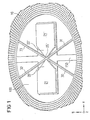
- Fig. 1 shows a schematic plan view of an embodiment of the micromechanical rotation rate sensor according to the invention.
- annular flywheel 10 is via a spiral spring device consisting of the two V-shaped spiral springs like this connected to the anchoring device 21, 21 ', 25, that the anchoring device 20 essentially in the ring center lies so that the annular flywheel 10 so that the annular flywheel mass is perpendicular to the substrate surface lying z-axis and that parallel to the substrate surface lying x- and y-axis elastic from their Rest position is deflectable.
- the anchoring device 21, 21 ', 25' has two opposite pedestals firmly connected to the substrate 100 21, 21 'on the wedge-shaped on the opposite sides are formed, the bridge 25 'the two Wedge tips connected together.
- the bridge 25 ' is floating suspended above the substrate 100 on the bases 21, 21 '.
- the opening angle is the for both V-shaped spiral springs Bending spring device the same, and the V-shaped bending springs the spiral spring device are in this way on the bridge 25 'attached so that they form a symmetrical X shape complete.
- the width and length of the legs 30, 31, 32, 33 of the V-shaped spiral springs can be Set the first natural frequency around the z axis.
- the opening angle between the respective spring legs can the natural frequency for the rotation from the Substrate level can be set around the x or y axis.
- the ratio of the natural frequencies to one another is determined in such a way that the sensor properties, e.g. Sensitivity, Immunity and temperature stability, one specific to the application accept optimized value.
- the opening angle is chosen such that the natural frequency around that perpendicular to the substrate surface lying z-axis is lower than any natural frequency by one axis of rotation lying parallel to the substrate surface, i.e. the x or y axis.
- the micromechanical rotation rate sensor according to this embodiment is preferably by silicon surface micromechanics manufactured.
- the geometry of the flywheel and the Bending spring arrangements are not limited to the examples shown.
- major deviations from the symmetrical arrangement around the anchoring then avoided if there is a risk that linear portions of the external acceleration falsify the measurement result.
Landscapes
- Physics & Mathematics (AREA)
- Engineering & Computer Science (AREA)
- General Physics & Mathematics (AREA)
- Radar, Positioning & Navigation (AREA)
- Remote Sensing (AREA)
- Gyroscopes (AREA)
- Micromachines (AREA)
Applications Claiming Priority (3)
| Application Number | Priority Date | Filing Date | Title |
|---|---|---|---|
| DE19945859A DE19945859A1 (de) | 1999-09-24 | 1999-09-24 | Mikromechanischer Drehratensensor |
| DE19945859 | 1999-09-24 | ||
| PCT/DE2000/002931 WO2001023837A1 (de) | 1999-09-24 | 2000-08-26 | Mikromechanischer drehratensensor |
Publications (2)
| Publication Number | Publication Date |
|---|---|
| EP1218693A1 EP1218693A1 (de) | 2002-07-03 |
| EP1218693B1 true EP1218693B1 (de) | 2004-11-03 |
Family
ID=7923206
Family Applications (1)
| Application Number | Title | Priority Date | Filing Date |
|---|---|---|---|
| EP00971236A Expired - Lifetime EP1218693B1 (de) | 1999-09-24 | 2000-08-26 | Mikromechanischer drehratensensor |
Country Status (5)
| Country | Link |
|---|---|
| US (1) | US6776041B1 (enExample) |
| EP (1) | EP1218693B1 (enExample) |
| JP (1) | JP4605736B2 (enExample) |
| DE (2) | DE19945859A1 (enExample) |
| WO (1) | WO2001023837A1 (enExample) |
Families Citing this family (10)
| Publication number | Priority date | Publication date | Assignee | Title |
|---|---|---|---|---|
| US6715352B2 (en) * | 2001-06-26 | 2004-04-06 | Microsensors, Inc. | Method of designing a flexure system for tuning the modal response of a decoupled micromachined gyroscope and a gyroscoped designed according to the method |
| DE10238893A1 (de) * | 2002-08-24 | 2004-03-04 | Robert Bosch Gmbh | Drehratensensor |
| DE102005032863A1 (de) * | 2005-07-11 | 2007-01-18 | Fraunhofer-Gesellschaft zur Förderung der angewandten Forschung e.V. | Mikroaktuator |
| WO2007125961A1 (ja) | 2006-04-28 | 2007-11-08 | Panasonic Electric Works Co., Ltd. | 静電容量式センサ |
| JP4600344B2 (ja) * | 2006-04-28 | 2010-12-15 | パナソニック電工株式会社 | 静電容量式センサ |
| DE102007035806B4 (de) * | 2007-07-31 | 2011-03-17 | Sensordynamics Ag | Mikromechanischer Drehratensensor |
| DE102007057044B4 (de) | 2007-09-10 | 2021-08-05 | Continental Teves Ag & Co. Ohg | Mikromechanische Feder |
| WO2012004825A1 (ja) * | 2010-07-05 | 2012-01-12 | パイオニア株式会社 | 回転振動型ジャイロ |
| US9932852B2 (en) | 2011-08-08 | 2018-04-03 | General Electric Company | Sensor assembly for rotating devices and methods for fabricating |
| JP2021067624A (ja) * | 2019-10-28 | 2021-04-30 | セイコーエプソン株式会社 | 慣性計測装置、電子機器及び移動体 |
Family Cites Families (5)
| Publication number | Priority date | Publication date | Assignee | Title |
|---|---|---|---|---|
| US5650568A (en) * | 1993-02-10 | 1997-07-22 | The Charles Stark Draper Laboratory, Inc. | Gimballed vibrating wheel gyroscope having strain relief features |
| DE19523895A1 (de) * | 1995-06-30 | 1997-01-02 | Bosch Gmbh Robert | Beschleunigungssensor |
| GB2318184B (en) * | 1996-10-08 | 2000-07-05 | British Aerospace | A rate sensor |
| US5955668A (en) * | 1997-01-28 | 1999-09-21 | Irvine Sensors Corporation | Multi-element micro gyro |
| DE19746127C1 (de) * | 1997-10-18 | 1999-05-12 | Bodenseewerk Geraetetech | Sensor zur Messung von Drehraten und Verfahren zu seiner Herstellung |
-
1999
- 1999-09-24 DE DE19945859A patent/DE19945859A1/de not_active Withdrawn
-
2000
- 2000-08-26 WO PCT/DE2000/002931 patent/WO2001023837A1/de not_active Ceased
- 2000-08-26 EP EP00971236A patent/EP1218693B1/de not_active Expired - Lifetime
- 2000-08-26 DE DE50008537T patent/DE50008537D1/de not_active Expired - Lifetime
- 2000-08-26 US US10/089,018 patent/US6776041B1/en not_active Expired - Lifetime
- 2000-08-26 JP JP2001527175A patent/JP4605736B2/ja not_active Expired - Lifetime
Also Published As
| Publication number | Publication date |
|---|---|
| US6776041B1 (en) | 2004-08-17 |
| JP4605736B2 (ja) | 2011-01-05 |
| WO2001023837A1 (de) | 2001-04-05 |
| DE50008537D1 (de) | 2004-12-09 |
| JP2003510591A (ja) | 2003-03-18 |
| EP1218693A1 (de) | 2002-07-03 |
| DE19945859A1 (de) | 2001-03-29 |
Similar Documents
| Publication | Publication Date | Title |
|---|---|---|
| DE68911294T2 (de) | Mikrobearbeiteter beschleunigungsmesser. | |
| DE69003339T2 (de) | Beschleunigungsmesser mit koplanaren symmetrischen kraftübertragern. | |
| EP2193335B1 (de) | Mikromechanischer drehratensensor | |
| DE69017213T2 (de) | Beschleunigungsmesser mit feedback. | |
| EP0906557B1 (de) | Drehratensensor mit entkoppelten orthogonalen primär- und sekundärschwingungen | |
| DE102008043524B4 (de) | Beschleunigungssensor und Verfahren zu seiner Herstellung | |
| DE69821005T2 (de) | Aufhängungsanordnung für halbleiterbeschleunigungsmesser | |
| DE60319528T2 (de) | Monolithischer beschleunigungsaufnehmer aus silizium | |
| DE69822756T2 (de) | Mikromechanischer Schwingkreisel | |
| EP0394305B1 (de) | Vorrichtung zur messung von beschleunigungen | |
| DE3638390A1 (de) | Vibrations-beschleunigungsmesser | |
| DE3509948A1 (de) | Planarer traegheitssensor | |
| DE60103363T2 (de) | Drehgeschwindigkeitssensor | |
| EP0275338B1 (de) | Biegefedergelenk und Verfahren zu seiner Herstellung | |
| DE69736731T2 (de) | Herstellungsverfahren eines Quartzvibrators | |
| DE10001361B4 (de) | Verfahren zum Herstellen eines Mikroträgheitssensors | |
| EP1218693B1 (de) | Mikromechanischer drehratensensor | |
| DE102010038809A1 (de) | Inertialsensor und Verfahren zum Herstellen eines Inertialsensors | |
| EP1198695B1 (de) | Verfahren zur herstellung einer torsionsfeder | |
| DE102021200483A1 (de) | Dreiachsiger Drehratensensor mit einem Substrat und einem Doppelrotor | |
| DE60318204T2 (de) | Verfahren zur herstellung eines monolithischen silizium-beschleunigungsaufnehmers | |
| DE102017219929B4 (de) | Mikromechanischer z-Inertialsensor | |
| EP0740793B1 (de) | Tunneleffekt-sensor | |
| DE69328381T2 (de) | Vorrichtung zur messung von kraftkomponenten in monokristallinem material, methode zur herstellung einer solchen vorrichtung sowie deren anwendung | |
| DE29617410U1 (de) | Drehratensensor mit entkoppelten orthogonalen Primär- und Sekundärschwingungen |
Legal Events
| Date | Code | Title | Description |
|---|---|---|---|
| PUAI | Public reference made under article 153(3) epc to a published international application that has entered the european phase |
Free format text: ORIGINAL CODE: 0009012 |
|
| 17P | Request for examination filed |
Effective date: 20020424 |
|
| AK | Designated contracting states |
Kind code of ref document: A1 Designated state(s): AT BE CH CY DE DK ES FI FR GB GR IE IT LI LU MC NL PT SE |
|
| AX | Request for extension of the european patent |
Free format text: AL;LT;LV;MK;RO;SI |
|
| GRAP | Despatch of communication of intention to grant a patent |
Free format text: ORIGINAL CODE: EPIDOSNIGR1 |
|
| GRAS | Grant fee paid |
Free format text: ORIGINAL CODE: EPIDOSNIGR3 |
|
| GRAA | (expected) grant |
Free format text: ORIGINAL CODE: 0009210 |
|
| AK | Designated contracting states |
Kind code of ref document: B1 Designated state(s): DE FR GB IT |
|
| REG | Reference to a national code |
Ref country code: GB Ref legal event code: FG4D Free format text: NOT ENGLISH |
|
| REF | Corresponds to: |
Ref document number: 50008537 Country of ref document: DE Date of ref document: 20041209 Kind code of ref document: P |
|
| REG | Reference to a national code |
Ref country code: IE Ref legal event code: FG4D Free format text: GERMAN |
|
| GBT | Gb: translation of ep patent filed (gb section 77(6)(a)/1977) |
Effective date: 20050211 |
|
| REG | Reference to a national code |
Ref country code: IE Ref legal event code: FD4D |
|
| PLBE | No opposition filed within time limit |
Free format text: ORIGINAL CODE: 0009261 |
|
| STAA | Information on the status of an ep patent application or granted ep patent |
Free format text: STATUS: NO OPPOSITION FILED WITHIN TIME LIMIT |
|
| ET | Fr: translation filed | ||
| 26N | No opposition filed |
Effective date: 20050804 |
|
| PGFP | Annual fee paid to national office [announced via postgrant information from national office to epo] |
Ref country code: FR Payment date: 20140819 Year of fee payment: 15 Ref country code: GB Payment date: 20140821 Year of fee payment: 15 |
|
| PGFP | Annual fee paid to national office [announced via postgrant information from national office to epo] |
Ref country code: IT Payment date: 20140827 Year of fee payment: 15 |
|
| GBPC | Gb: european patent ceased through non-payment of renewal fee |
Effective date: 20150826 |
|
| PG25 | Lapsed in a contracting state [announced via postgrant information from national office to epo] |
Ref country code: IT Free format text: LAPSE BECAUSE OF NON-PAYMENT OF DUE FEES Effective date: 20150826 |
|
| REG | Reference to a national code |
Ref country code: FR Ref legal event code: ST Effective date: 20160429 |
|
| PG25 | Lapsed in a contracting state [announced via postgrant information from national office to epo] |
Ref country code: GB Free format text: LAPSE BECAUSE OF NON-PAYMENT OF DUE FEES Effective date: 20150826 |
|
| PG25 | Lapsed in a contracting state [announced via postgrant information from national office to epo] |
Ref country code: FR Free format text: LAPSE BECAUSE OF NON-PAYMENT OF DUE FEES Effective date: 20150831 |
|
| PGFP | Annual fee paid to national office [announced via postgrant information from national office to epo] |
Ref country code: DE Payment date: 20191021 Year of fee payment: 20 |