EP1216769B1 - Verfahren zur Herstellung eines umfänglich geschlossenen Hohlprofiles und eine Vorrichtung zur Durchführung desselben - Google Patents
Verfahren zur Herstellung eines umfänglich geschlossenen Hohlprofiles und eine Vorrichtung zur Durchführung desselben Download PDFInfo
- Publication number
- EP1216769B1 EP1216769B1 EP01129173A EP01129173A EP1216769B1 EP 1216769 B1 EP1216769 B1 EP 1216769B1 EP 01129173 A EP01129173 A EP 01129173A EP 01129173 A EP01129173 A EP 01129173A EP 1216769 B1 EP1216769 B1 EP 1216769B1
- Authority
- EP
- European Patent Office
- Prior art keywords
- membrane
- blank
- hollow profile
- tool
- pressure
- Prior art date
- Legal status (The legal status is an assumption and is not a legal conclusion. Google has not performed a legal analysis and makes no representation as to the accuracy of the status listed.)
- Expired - Lifetime
Links
- 238000000034 method Methods 0.000 title claims description 34
- 239000012528 membrane Substances 0.000 claims description 74
- 238000004519 manufacturing process Methods 0.000 claims description 9
- 239000012530 fluid Substances 0.000 claims description 4
- 230000002093 peripheral effect Effects 0.000 claims description 3
- 210000004379 membrane Anatomy 0.000 description 59
- 239000000463 material Substances 0.000 description 14
- 230000009172 bursting Effects 0.000 description 2
- 229920001971 elastomer Polymers 0.000 description 2
- 230000005484 gravity Effects 0.000 description 2
- 239000000725 suspension Substances 0.000 description 2
- 230000009466 transformation Effects 0.000 description 2
- 230000037303 wrinkles Effects 0.000 description 2
- 208000034656 Contusions Diseases 0.000 description 1
- 238000004026 adhesive bonding Methods 0.000 description 1
- 230000015572 biosynthetic process Effects 0.000 description 1
- 230000003750 conditioning effect Effects 0.000 description 1
- 238000002788 crimping Methods 0.000 description 1
- 230000007547 defect Effects 0.000 description 1
- 230000000694 effects Effects 0.000 description 1
- 239000000806 elastomer Substances 0.000 description 1
- 231100001261 hazardous Toxicity 0.000 description 1
- 230000001404 mediated effect Effects 0.000 description 1
- 238000010327 methods by industry Methods 0.000 description 1
- 238000002360 preparation method Methods 0.000 description 1
- 238000007493 shaping process Methods 0.000 description 1
- 239000007787 solid Substances 0.000 description 1
Images


Classifications
-
- B—PERFORMING OPERATIONS; TRANSPORTING
- B21—MECHANICAL METAL-WORKING WITHOUT ESSENTIALLY REMOVING MATERIAL; PUNCHING METAL
- B21D—WORKING OR PROCESSING OF SHEET METAL OR METAL TUBES, RODS OR PROFILES WITHOUT ESSENTIALLY REMOVING MATERIAL; PUNCHING METAL
- B21D26/00—Shaping without cutting otherwise than using rigid devices or tools or yieldable or resilient pads, i.e. applying fluid pressure or magnetic forces
- B21D26/02—Shaping without cutting otherwise than using rigid devices or tools or yieldable or resilient pads, i.e. applying fluid pressure or magnetic forces by applying fluid pressure
- B21D26/021—Deforming sheet bodies
-
- B—PERFORMING OPERATIONS; TRANSPORTING
- B21—MECHANICAL METAL-WORKING WITHOUT ESSENTIALLY REMOVING MATERIAL; PUNCHING METAL
- B21D—WORKING OR PROCESSING OF SHEET METAL OR METAL TUBES, RODS OR PROFILES WITHOUT ESSENTIALLY REMOVING MATERIAL; PUNCHING METAL
- B21D26/00—Shaping without cutting otherwise than using rigid devices or tools or yieldable or resilient pads, i.e. applying fluid pressure or magnetic forces
- B21D26/02—Shaping without cutting otherwise than using rigid devices or tools or yieldable or resilient pads, i.e. applying fluid pressure or magnetic forces by applying fluid pressure
-
- B—PERFORMING OPERATIONS; TRANSPORTING
- B21—MECHANICAL METAL-WORKING WITHOUT ESSENTIALLY REMOVING MATERIAL; PUNCHING METAL
- B21D—WORKING OR PROCESSING OF SHEET METAL OR METAL TUBES, RODS OR PROFILES WITHOUT ESSENTIALLY REMOVING MATERIAL; PUNCHING METAL
- B21D26/00—Shaping without cutting otherwise than using rigid devices or tools or yieldable or resilient pads, i.e. applying fluid pressure or magnetic forces
- B21D26/02—Shaping without cutting otherwise than using rigid devices or tools or yieldable or resilient pads, i.e. applying fluid pressure or magnetic forces by applying fluid pressure
- B21D26/021—Deforming sheet bodies
- B21D26/027—Means for controlling fluid parameters, e.g. pressure or temperature
-
- B—PERFORMING OPERATIONS; TRANSPORTING
- B21—MECHANICAL METAL-WORKING WITHOUT ESSENTIALLY REMOVING MATERIAL; PUNCHING METAL
- B21D—WORKING OR PROCESSING OF SHEET METAL OR METAL TUBES, RODS OR PROFILES WITHOUT ESSENTIALLY REMOVING MATERIAL; PUNCHING METAL
- B21D26/00—Shaping without cutting otherwise than using rigid devices or tools or yieldable or resilient pads, i.e. applying fluid pressure or magnetic forces
- B21D26/02—Shaping without cutting otherwise than using rigid devices or tools or yieldable or resilient pads, i.e. applying fluid pressure or magnetic forces by applying fluid pressure
- B21D26/021—Deforming sheet bodies
- B21D26/031—Mould construction
-
- Y—GENERAL TAGGING OF NEW TECHNOLOGICAL DEVELOPMENTS; GENERAL TAGGING OF CROSS-SECTIONAL TECHNOLOGIES SPANNING OVER SEVERAL SECTIONS OF THE IPC; TECHNICAL SUBJECTS COVERED BY FORMER USPC CROSS-REFERENCE ART COLLECTIONS [XRACs] AND DIGESTS
- Y10—TECHNICAL SUBJECTS COVERED BY FORMER USPC
- Y10T—TECHNICAL SUBJECTS COVERED BY FORMER US CLASSIFICATION
- Y10T29/00—Metal working
- Y10T29/49—Method of mechanical manufacture
- Y10T29/49805—Shaping by direct application of fluent pressure
Definitions
- the invention relates to a method for producing a perimeter closed hollow profiles according to the preamble of Patent claim 1 and an apparatus for carrying it out according to the preamble of claim 9.
- a generic method or a generic device is known from EP 0913 277 A1.
- Suspension arm of a suspension removable consisting of a tube is manufactured by hydroforming.
- the wishbone has various cross-sectional shapes, one being a flattened Represents rectangle.
- To form this form is the circular cylindrical pre-bent tube in a two-part hydroforming inserted and during the closing process squeezed together by the two die parts. Subsequently, will when the tool is closed, the tube is widened by means of internal high pressure, until it is true to the Gesenkgravur contour true and thus to obtain the desired rectangular flat final shape.
- the contour of the support surface of the stamp unchangeable, so that the plant of the tube - be during the squeezing process or during the expansion phase - is not evenly distributed at any time, which is too uneven Supporting the pipe leads and therefore to the failure of the Pipe at this supported point or in the adjacent Areas contributes to the backstop.
- the invention is based on the object, a generic Method and a corresponding generic device to the effect to further develop that in a simple way a production a hollow section is made possible in the case of large Expansions of the hollow profile (greater than or equal to the Breaking strain of the material) the process safety in sufficient Dimensions is guaranteed.
- the membrane becomes a flexible counterholder formed, which can be any shape of the hollow section blank during expansion and also in others Forming processes true to contour and over a relatively large area adjust large partial circumference of the hollow section blank can.
- the contour-matching achieved by the external pressurization Expansion and support force of the membrane can by very easy to handle control parameters of printing be exactly adapted to the transformation progress. All in all, So by the large-scale plant - when using several circumferentially more distributed membrane circumferentially more complete Plant - during each forming phase and by the exact Stitzkraftdostechnik receives the reshaped hollow section blank always the appropriate uniform support force, which is a failure prevents the blank material during expansion.
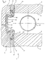
- a device 1 for producing a circumferential closed flattened hollow profiles 2 (FIG. 4) are shown, essentially divided into two lateral tools Hydroforming die, a membrane 12 and a Flatten device exists.
- the side tools can each be integrally formed, wherein a pressure medium supply 20 is incorporated there.
- the lateral ones Tools also in several parts, in an upper side tool 3 and a lower side tool 4, be executed, wherein in the parting line of the two side tools 3 and 4, the Print medium supply 20 can run.
- For equipping the forming tool with a blank 10 is to use a manipulator the blank 10 until the two pairs of side tools 3,4 have closed like a baking around the blank 10. After reshaping, the finished hollow section in easy way when moving apart the side tools.
- the flattening device the pair of side tools. 3 and / or the pair of side tools 4 by means of a corresponding designed engraving itself may be included in the present Embodiment
- a single Stamp it is also conceivable the use of a single Stamp.
- the punches 6 and 7 can be adapted to the longitudinal extent of hydroforming and thus to the entire deformable part of the hollow section blank 10 throughout trained or alternatively only locally to act on a Part of the blank 10 may be arranged.
- the stamps 6.7 have a flat end face, so on the one hand the required flat shape of the hollow section 2 is achieved and on the other hand, on the blank 10 no hazardous to process Notches due to sharp-edged unevenness of the stamp surface arise.
- an elastic membrane 12 for example made of an elastomer or a rubber, attached.
- the attachment of the membrane 12 can be carried out in many ways be, for example, insoluble by gluing, screwing, Annieten and the like.
- the membrane 12 in an advantageous manner when worn interchangeable both transverse to the longitudinal extent of the tool and parallel to the punches 6 and 7 lying flange-like ends 13 in each case a holder 14 was added.
- the holder 14 is detachable on the inside 11 of the tool attached, wherein the holder 14 is open to the inside 11 has the receptacle for the membrane 12 forming recess 15, between the walls and the opposite wall portion 16 of the tool inside 11, the membrane flanges 13 are trapped.
- the shape of the Membrane 12 is in the inside 11 of the tool a longitudinal the middle part 17 of the membrane 12 extending recess 18th incorporated to accommodate the diaphragm 12 so far that in the Non-use position of the membrane 12 and in the last forming phase of the blank 10 of the mold space 9 membrane-free and thus the membrane 12 on the one hand when loading the mold space 9 with a blank 10 is not a hindrance and the other during pull back the forming of the blank 10 from the mold space 9 can.
- the recess bottom 19 opens a channel-like pressure medium supply 20 off, with one located outside the tool Pressure generator is connected.
- the membrane 12 covers thus the recess 18 including the mouth of the print medium supply 20 high pressure-tight, whereby upon introduction of the pressure medium between the recess base 19 and facing this Outside 21 of the membrane 12, a pressure chamber 22 is formed becomes. Due to the formation of the recess 18 of the over the pressure medium mediated pressure evenly over the entire - with the exception of the clamped flanges 13 - membrane 12 distributed, so that local damage-induced strains of the membrane 12 avoided when pressurized and the desired Appendix to the hollow section blank 10 sufficiently over a partial circumferential area of the blank 10 can be achieved.
- the Although pressure medium may be gaseous, it is due here its incompressible properties when supporting during the forming of the blank 10 are very advantageous a pressurized fluid.
- the hydroforming instead of side tools 3,4 a and a lower tool, whereby the loading of the Form space 14 can be relatively simple.
- the membrane 12th the upper tool connects to the lower tool, the Membrane 12 stretched when opening and closing the tool and compressed, whereby the membrane 12 an increased wear is exposed.
- this can be achieved by a removable only the mold space covering lid part in the upper tool be circumvented, the membrane 12 in the opening and Closing movement of the forming tool remains unclaimed.
- a first Flattening of the blank 10 done, which in the flattened Condition then expanded by means of hydroforming becomes.
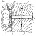
- the Membrane 12 everts and expands to the blank 10, until the membrane 12 fits snugly against this on a partial circumference area.
- the punch 6,7 to each other drive and thus reduce the cavity 9, the blank 10 squeezed and in the width direction to the recess 18th widened.
- the pressure in the pressure chamber 22 must be reduced to allow this broadening. This gives way to the elastic Membrane 12 from the mold space 9 in its recess 18th back until they completely leave the field of action of the punch 6.7 Has.
- the membrane 12 remains at elevated pressure from the pressure chamber 22nd then acts on the side of the punch 6,7 stand and support the blank 10 so that on this one with the stamp outside 23 flush final wall 24 are formed can.
- the achieved flush is from the requirement to the Cross-sectional shape (here: rectangular cross-section) depends.
- the membrane 12 is pressurized from the pressure chamber 22, Which thereby at a partial peripheral area of the blank 10th and applies to a portion of the punch faces 5 (Fig. 2).
- a fluidic internal high pressure is then the blank 10 widened, wherein throughout the entire Expansion of the membrane 12 pressurized to the blank 10 is pressed on said partial circumference area.
- the membrane 12 supports this there material-soothing and form-retaining, so that the expansion phase is completely reliable (FIG. 3).
- the membrane 12 urges the membrane 12 to Pressure chamber 22 out back, with increasing degree of expansion of the Support pressure in the pressure chamber 22 continuously adapted reduced becomes.
- the membrane 12 during the expansion of the blank 10 occurs no or a very low friction of the Blank material on the membrane 12, as these are not solid is and elastically mitverformt.
- the diameter of the blank 10 is roughly approximated after completion of expansion as big as the punch width.
- the punches are 6,7 in the arrow direction driven towards each other, whereby the expanded blank 10 is compressed.
- the blank 10 is not inevitably be supported by the membrane 12 and under a fluidic support pressure, which is smaller than the expansion pressure It can be, has to stand, it is for further process security advantageous if this is given.
- the blank 10 wrinkle-free in a flattened final shape of the circumferentially closed Hollow sections 2 pressed with rectangular cross-section.
- the blank 10 is thereby further widened without damage, until it has taken the final shape.
- the flattening-related Broadening complements that created by the expansion Main part of the whole broadening. According to FIG.
- the blank 10 steadily supported and during the flattening pressurized by the membrane 12 such that upon reaching the flush of the flattened blank 10 with the outside 23 of the punch 6.7, the lateral end contour of the hollow section. 2 is trained.
- the middle part 17 of the membrane 12 lies here along the outside 23 of the punch 6.7. Also in the flattening the pressure in the pressure chamber 22 is successively reduced, so that the membrane 12 until reaching the level of the Final contour of the hollow section 2 supporting wall 24 with the punch outside 23 can withdraw elastically.
- the device of the invention allows compared to previous Processes that two in the shaping direction different manufacturing steps, usually in two Manufacturing stages would have to be produced, in a hydroforming operation can be represented. Furthermore, you can with the flexible membrane 12 workpieces with widenings to be realized, due to their geometric design and the associated friction between the workpiece and tools can not be transformed process-safe. For example It may be at the mentioned workpieces for a long time IHU components act, the narrow tapered expansion areas must have, as in the motor vehicle body of the under the windbreak extending cross member.
Landscapes
- Physics & Mathematics (AREA)
- Fluid Mechanics (AREA)
- Engineering & Computer Science (AREA)
- Mechanical Engineering (AREA)
- Shaping Metal By Deep-Drawing, Or The Like (AREA)
Description
Claims (17)
- Verfahren zur Herstellung eines umfänglich geschlossenen Hohlprofiles, wobei ein Hohlprofilrohling in einem Innenhochdruckumformwerkzeug mittels fluidischen Innenhochdruck aufgeweitet wird, wonach dieser die Endform des Hohlprofiles erreicht,
dadurch gekennzeichnet, daß der Hohlprofilrohling (10) auf zumindest einem Teilumfangsbereich während der Aufweitung mittels wenigstens einer an der dem Rohling (10) zugewandten Innenseite (11) des Werkzeuges befestigten und mit einem von außen wirkenden steuerbaren Druck beaufschlagbaren Membrane (12) abgestützt wird,- wobei diese mit dem Fortlauf der Aufweitung unter Reduzierung des auf die Membrane (12) wirkenden Stützdruckes elastisch zurückweicht. - Verfahren nach Anspruch 1,
dadurch gekennzeichnet, daß der Hohlprofilrohling (10) im Innenhochdruckumformwerkzeug abgeplattet wird. - Verfahren nach einem der Ansprüche 1 oder 2,
dadurch gekennzeichnet, daß der Hohlprofilrohling (10) über seine gesamte Längserstreckung hinweg von der Membrane (12) abgestützt wird. - Verfahren nach einem der Ansprüche 2 oder 3,
dadurch gekennzeichnet, daß der Hohlprofilrohling (10) zusätzlich während des Abplattvorganges von der Membran (12) abgestützt wird. - Verfahren nach einem der Ansprüche 2 bis 4,
dadurch gekennzeichnet, daß zuerst eine freie Aufweitung des Hohlprofilrohlinges (10) erfolgt, bis dieser eine Abplattvorrichtung (6,7) des Innenhochdruckumformwerkzeuges kontaktiert, und daß anschließend das Abplatten des aufgeweiteten Rohlings (10) erfolgt, welches durch stetiges Abstützen des Rohlings (10) durch die Membran (12) begleitet wird. - Verfahren nach Anspruch 5,
dadurch gekennzeichnet, daß der Rohling (10) durch die Membran (12) derart druckbeaufschlagt wird, daß im Erreichen der Bündigkeit des abgeplatteten Rohlings (10) mit der Außenseite (23) der stempelartigen Abplattvorrichtung (6, 7) die seitliche Endkontur des Hohlprofiles (2) ausgebildet ist. - Verfahren nach einem der Ansprüche 1 bis 6,
dadurch gekennzeichnet, daß abschließend der Hohlprofilrohling (10) durch einen den Aufweitdruck übersteigenden Innenhochdruck in die Endform des Hohlprofiles (2) kalibriert wird. - Verfahren nach einem der Ansprüche 5 oder 6,
dadurch gekennzeichnet, daß das Abplatten bei einem den Hohlprofilrohling (10) von innen stützenden Innenhochdruck, der kleiner als der Aufweitdruck ist, unmittelbar in die Endform des Hohlprofiles (2) führt. - Vorrichtung zur Herstellung eines umfänglich geschlossenen Hohlprofiles, mit einem Innenhochdruckumformwerkzeug, in dem ein Hohlprofilrohling mittels fluidischem Innenhochdruck aufweitbar ist,
dadurch gekennzeichnet, daß an der Werkzeuginnenseite (11) zumindest eine elastische seitlich des Eingriffsfeldes des Stempels (6,7) verlaufende Membran (12) befestigt ist, welche eine mit einem außerhalb des Werkzeuges befindlichen Druckerzeuger verbundene Druckmediumzuführung (20) hochdruckdicht überdeckt, die als Kanal durch das Werkzeug verläuft und an dessen Innenseite (11) zum Formraum (9) hin ausmündet, und welche über die Druckmediumzuführung (20) druckbeaufschlagt an dem umzuformenden Hohlprofilrohling (10) an zumindest einem Teilumfangsbereich anlegbar ist. - Vorrichtung nach Anspruch 9,
dadurch gekennzeichnet, daß die Vorrichtung eine Abplattvorrichtung beinhaltet, die in das Innenhochdruckumformwerkzeug integriert ist und mittels derer der Hohlprofilrohling (10) abplattbar ist. - Vorrichtung nach Anspruch 10,
dadurch gekennzeichnet, daß die Abplattvorrichtung aus zumindest einem in einer Durchführung (8) des Werkzeuges verschiebbar geführten Stempel (6,7) besteht. - Vorrichtung nach einem der Ansprüche 9 bis 11,
dadurch gekennzeichnet, daß die Membran (12) sich längs des gesamten Formraumes (9) des Werkzeuges erstreckt. - Vorrichtung nach einem der Ansprüche 9 bis 12,
dadurch gekennzeichnet, daß die Membran (12) an beiden quer zur Längserstreckung des Werkzeuges liegenden Enden (13) in jeweils einem Halter (14) aufgenommen ist, der an der Innenseite (11) des Werkzeuges angeordnet ist. - Vorrichtung nach Anspruch 13,
dadurch gekennzeichnet, daß die Membran (12) zwischen der Werkzeuginnenseite (11) und einer Wandung der Halteraufnahme festgeklemmt ist. - Vorrichtung nach einem der Ansprüche 9 bis 14,
dadurch gekennzeichnet, daß das die Membran zum Hohlprofilrohling (10) hin beaufschlagende Druckmedium ein Druckfluid ist. - Vorrichtung nach einem der Ansprüche 11 bis 15,
dadurch gekennzeichnet, daß der Stempel (6,7) eine ebene Stirnfläche aufweist. - Vorrichtung nach einem der Ansprüche 9 bis 16,
dadurch gekennzeichnet, daß in die Werkzeuginnenseite (6,7) eine längs der Membran (12) verlaufende Ausnehmung (18) eingearbeitet ist, welche von der Membran (12) überdeckt ist und in die die Druckmediumzuführung (20) einmündet, und daß zwischen dem Ausnehmungsgrund (19) und der diesem zugewandten Außenseite (21) der Membran (12) ein Druckraum (22) ausbildbar ist.
Applications Claiming Priority (2)
| Application Number | Priority Date | Filing Date | Title |
|---|---|---|---|
| DE10065033 | 2000-12-23 | ||
| DE10065033A DE10065033C1 (de) | 2000-12-23 | 2000-12-23 | Verfahren zur Herstellung eines umfänglich geschlossenen Hohlprofiles und eine Vorrichtung zur Durchführung desselben |
Publications (3)
| Publication Number | Publication Date |
|---|---|
| EP1216769A2 EP1216769A2 (de) | 2002-06-26 |
| EP1216769A3 EP1216769A3 (de) | 2003-11-19 |
| EP1216769B1 true EP1216769B1 (de) | 2005-10-12 |
Family
ID=7668996
Family Applications (1)
| Application Number | Title | Priority Date | Filing Date |
|---|---|---|---|
| EP01129173A Expired - Lifetime EP1216769B1 (de) | 2000-12-23 | 2001-12-08 | Verfahren zur Herstellung eines umfänglich geschlossenen Hohlprofiles und eine Vorrichtung zur Durchführung desselben |
Country Status (4)
| Country | Link |
|---|---|
| US (1) | US6634198B2 (de) |
| EP (1) | EP1216769B1 (de) |
| CA (1) | CA2366209C (de) |
| DE (2) | DE10065033C1 (de) |
Families Citing this family (8)
| Publication number | Priority date | Publication date | Assignee | Title |
|---|---|---|---|---|
| CA2350731C (en) * | 2000-06-16 | 2004-12-07 | Toyota Jidosha Kabushiki Kaisha | Mold clamping apparatus and mold clamping method |
| DE10121787C1 (de) * | 2001-05-04 | 2002-07-11 | Daimler Chrysler Ag | Verfahren und Vorrichtung zur Herstellung von Nebenformelementen |
| US7509827B2 (en) | 2002-05-08 | 2009-03-31 | Avure Technologies Ab | Device and method for expansion forming |
| DE102005013689B3 (de) * | 2005-03-21 | 2006-01-05 | Forschungsgesellschaft Umformtechnik Mbh | Vorrichtung und Verfahren zum Trennen oder Lochen eines nach dem Innenhochdruckumformverfahren hergestellten Werkstücks |
| DE102006012625C5 (de) * | 2006-03-20 | 2010-06-17 | Audi Ag | Verfahren zur Herstellung von Profilen |
| US7827838B2 (en) * | 2008-05-05 | 2010-11-09 | Ford Global Technologies, Llc | Pulsed electro-hydraulic calibration of stamped panels |
| CN110450268B (zh) * | 2019-09-12 | 2024-07-12 | 广东金马领科智能科技有限公司 | 高压注浆成型生产线、成型方法及系统 |
| CN116944329B (zh) * | 2023-09-21 | 2023-12-12 | 太原理工大学 | 一种基于冲击液压原理用于板材加工的超高速成形装置 |
Family Cites Families (13)
| Publication number | Priority date | Publication date | Assignee | Title |
|---|---|---|---|---|
| US2423862A (en) * | 1944-12-30 | 1947-07-15 | Casimer E Vorobik | Binding and covering apparatus |
| US3888098A (en) * | 1974-02-27 | 1975-06-10 | Boeing Co | Liquid metal core transpactor elements for electromagnetic forming tools |
| US4840053A (en) * | 1987-07-29 | 1989-06-20 | Mitsui & Co., Ltd. | Method for manufacturing a pipe with projections |
| DE4201819A1 (de) * | 1991-01-28 | 1992-07-30 | Mannesmann Ag | Verfahren und vorrichtung zum hydraulischen aufweiten von rohrfoermigen hohlprofilen |
| US5829137A (en) * | 1995-04-03 | 1998-11-03 | Grassi; John R. | Method for manufacturing wheels |
| US5813266A (en) * | 1995-10-31 | 1998-09-29 | Greenville Tool & Die Company | Method of forming and piercing a tube |
| ATE231754T1 (de) * | 1997-07-18 | 2003-02-15 | Cosma Int Inc | Innenhochdruckformung eines rohrförmigen rohlings mit ovalem querschnitt, sowie innenhochdruckumformvorrichtung |
| DE19733474C2 (de) * | 1997-08-02 | 1999-12-09 | Daimler Chrysler Ag | Verfahren und Vorrichtung zur Herstellung von Nebenformelementen an Hohlprofilen |
| JP3206505B2 (ja) * | 1997-08-06 | 2001-09-10 | 住友金属工業株式会社 | 金属管の液圧バルジ加工方法および液圧バルジ加工装置 |
| US6070445A (en) * | 1997-10-29 | 2000-06-06 | Trw Inc. | Method of manufacturing the control arm |
| US6415638B1 (en) * | 1999-03-26 | 2002-07-09 | Nissan Motor Co., Ltd. | Method and device for forming tubular work into shaped hollow product by using tubular hydroforming |
| US6134931A (en) * | 1999-05-26 | 2000-10-24 | Husky Injection Molding Systems Ltd. | Process and apparatus for forming a shaped article |
| DE10121787C1 (de) * | 2001-05-04 | 2002-07-11 | Daimler Chrysler Ag | Verfahren und Vorrichtung zur Herstellung von Nebenformelementen |
-
2000
- 2000-12-23 DE DE10065033A patent/DE10065033C1/de not_active Expired - Fee Related
-
2001
- 2001-12-08 EP EP01129173A patent/EP1216769B1/de not_active Expired - Lifetime
- 2001-12-08 DE DE50107673T patent/DE50107673D1/de not_active Expired - Lifetime
- 2001-12-21 CA CA002366209A patent/CA2366209C/en not_active Expired - Fee Related
- 2001-12-21 US US10/026,090 patent/US6634198B2/en not_active Expired - Fee Related
Also Published As
| Publication number | Publication date |
|---|---|
| DE50107673D1 (de) | 2005-11-17 |
| EP1216769A3 (de) | 2003-11-19 |
| CA2366209C (en) | 2006-10-24 |
| CA2366209A1 (en) | 2002-06-23 |
| EP1216769A2 (de) | 2002-06-26 |
| US20020088263A1 (en) | 2002-07-11 |
| DE10065033C1 (de) | 2002-07-11 |
| US6634198B2 (en) | 2003-10-21 |
Similar Documents
| Publication | Publication Date | Title |
|---|---|---|
| DE69906093T2 (de) | Verfahren zum hydroformen von rohrförmigen bauteilen | |
| EP1796859B1 (de) | Verfahren und vorrichtung zur herstellung eines längsnahtgeschweissten hohlprofils | |
| WO1992013653A1 (de) | Verfahren zum hydrostatischen umformen von hohlkörpern aus kaltumformbarem metall und vorrichtung zur durchführung des verfahrens | |
| DE10043209A1 (de) | Flexibles Werkzeug zur Umformung eines Werkstücks | |
| DE2127367B2 (de) | Vorrichtungen zum tiefziehen von schalen mit sich verjuengenden seitenwaenden aus duennem metallblech oder folie | |
| DE19719629C2 (de) | Verfahren und Einrichtung zur Herstellung von Kraftfahrzeugachsgehäusen | |
| DE19833006B4 (de) | Verfahren und Vorrichtung zur Herstellung rohrförmiger gebogener Hohlkörper durch Innenhochdruckumformen | |
| DE19717953A1 (de) | Verfahren zum hydromechanischen Stülpziehen von Metallblechen | |
| DE10065033C1 (de) | Verfahren zur Herstellung eines umfänglich geschlossenen Hohlprofiles und eine Vorrichtung zur Durchführung desselben | |
| EP1781430B1 (de) | Verfahren und vorrichtung zum herstellen eines längsnahtgeschweissten hohlprofils | |
| EP0894548B1 (de) | Verfahren und Vorrichtung zur Herstellung von Nebenformelementen | |
| DE10322567B4 (de) | Vorrichtung zum Biegen eines Rohres | |
| DE102004054120B4 (de) | Verfahren zum Umformen einer großflächigen Blechplatine zu einem Formteil, wie einem Außenhautteil einer Kraftfahrzeugkarosserie | |
| EP2036628B1 (de) | Verfahren und Vorrichtung zur Herstellung eines Ausbuchtungen aufweisenden Werkstückes mittels eines Druckmediums | |
| DE19751408C2 (de) | Verfahren und Vorrichtung zur Herstellung eines Integralgehäuses für Hydrolenkung | |
| DE102021006400B3 (de) | Innenhochdruckumform-Werkzeugvorrichtung und Verfahren zur Herstellung eines Hohlkörpers durch Innenhochdruckumformen | |
| EP0876860B1 (de) | Verfahren und Einrichtung zur Herstellung von ausgebauchten Hohlprofilen | |
| DE102007017030B3 (de) | Verfahren und Vorrichtung zum Herstellen eines Innenhochdruckumformteils | |
| DE19533828C2 (de) | Vorrichtung zum Innenhochdruckumformen von rohrförmigen Rohlingen | |
| DE102007017190A1 (de) | Verfahren zum Verbinden eines Innenhochdruckumformteils mit einem Anschlussbauteil sowie Innenhochdruckumformwerkzeug | |
| DE102006052696A1 (de) | Verfahren und Vorrichtung zum Umformen von Halbzeugen | |
| EP1283754B1 (de) | Verfahren und vorrichtung zur hochdruckumformung | |
| DE102024208384B3 (de) | Verfahren zum Aufweiten und Anlegen eines Rollbalgs an ein Anschlussteil einer Luftfeder und Vorrichtung zum Durchführen solch eines Verfahrens | |
| DE102005036419A1 (de) | Verfahren und Vorrichtung zur Herstellung eines ausgebauchten Hohlprofils, insbesondere eines Gasgeneratorgehäuses für eine Airbageinrichtung | |
| DE10302883B4 (de) | Vulkanisationsverfahren und Vulkanisationsvorrichtung mit Balg für PKW-Luftfedern |
Legal Events
| Date | Code | Title | Description |
|---|---|---|---|
| PUAI | Public reference made under article 153(3) epc to a published international application that has entered the european phase |
Free format text: ORIGINAL CODE: 0009012 |
|
| AK | Designated contracting states |
Kind code of ref document: A2 Designated state(s): AT BE CH CY DE DK ES FI FR GB GR IE IT LI LU MC NL PT SE TR |
|
| AX | Request for extension of the european patent |
Free format text: AL;LT;LV;MK;RO;SI |
|
| PUAL | Search report despatched |
Free format text: ORIGINAL CODE: 0009013 |
|
| AK | Designated contracting states |
Kind code of ref document: A3 Designated state(s): AT BE CH CY DE DK ES FI FR GB GR IE IT LI LU MC NL PT SE TR |
|
| AX | Request for extension of the european patent |
Extension state: AL LT LV MK RO SI |
|
| 17P | Request for examination filed |
Effective date: 20031013 |
|
| AKX | Designation fees paid |
Designated state(s): DE ES FR GB |
|
| GRAP | Despatch of communication of intention to grant a patent |
Free format text: ORIGINAL CODE: EPIDOSNIGR1 |
|
| GRAS | Grant fee paid |
Free format text: ORIGINAL CODE: EPIDOSNIGR3 |
|
| GRAA | (expected) grant |
Free format text: ORIGINAL CODE: 0009210 |
|
| AK | Designated contracting states |
Kind code of ref document: B1 Designated state(s): DE ES FR GB |
|
| REG | Reference to a national code |
Ref country code: GB Ref legal event code: FG4D Free format text: NOT ENGLISH |
|
| REF | Corresponds to: |
Ref document number: 50107673 Country of ref document: DE Date of ref document: 20051117 Kind code of ref document: P |
|
| PGFP | Annual fee paid to national office [announced via postgrant information from national office to epo] |
Ref country code: ES Payment date: 20051216 Year of fee payment: 5 |
|
| GBT | Gb: translation of ep patent filed (gb section 77(6)(a)/1977) |
Effective date: 20051202 |
|
| PG25 | Lapsed in a contracting state [announced via postgrant information from national office to epo] |
Ref country code: ES Free format text: LAPSE BECAUSE OF FAILURE TO SUBMIT A TRANSLATION OF THE DESCRIPTION OR TO PAY THE FEE WITHIN THE PRESCRIBED TIME-LIMIT Effective date: 20060123 |
|
| ET | Fr: translation filed | ||
| PLBE | No opposition filed within time limit |
Free format text: ORIGINAL CODE: 0009261 |
|
| STAA | Information on the status of an ep patent application or granted ep patent |
Free format text: STATUS: NO OPPOSITION FILED WITHIN TIME LIMIT |
|
| 26N | No opposition filed |
Effective date: 20060713 |
|
| PGFP | Annual fee paid to national office [announced via postgrant information from national office to epo] |
Ref country code: GB Payment date: 20061221 Year of fee payment: 6 |
|
| PGFP | Annual fee paid to national office [announced via postgrant information from national office to epo] |
Ref country code: FR Payment date: 20061212 Year of fee payment: 6 |
|
| GBPC | Gb: european patent ceased through non-payment of renewal fee |
Effective date: 20071208 |
|
| REG | Reference to a national code |
Ref country code: FR Ref legal event code: ST Effective date: 20081020 |
|
| PG25 | Lapsed in a contracting state [announced via postgrant information from national office to epo] |
Ref country code: GB Free format text: LAPSE BECAUSE OF NON-PAYMENT OF DUE FEES Effective date: 20071208 |
|
| PG25 | Lapsed in a contracting state [announced via postgrant information from national office to epo] |
Ref country code: FR Free format text: LAPSE BECAUSE OF NON-PAYMENT OF DUE FEES Effective date: 20071231 |
|
| REG | Reference to a national code |
Ref country code: FR Ref legal event code: CD Ref country code: FR Ref legal event code: CA |
|
| PGFP | Annual fee paid to national office [announced via postgrant information from national office to epo] |
Ref country code: DE Payment date: 20100511 Year of fee payment: 9 |
|
| REG | Reference to a national code |
Ref country code: DE Ref legal event code: R119 Ref document number: 50107673 Country of ref document: DE Effective date: 20110701 |
|
| PG25 | Lapsed in a contracting state [announced via postgrant information from national office to epo] |
Ref country code: DE Free format text: LAPSE BECAUSE OF NON-PAYMENT OF DUE FEES Effective date: 20110701 |