EP1216157B1 - Stanzvorrichtung für blattstapel - Google Patents
Stanzvorrichtung für blattstapel Download PDFInfo
- Publication number
- EP1216157B1 EP1216157B1 EP00956309A EP00956309A EP1216157B1 EP 1216157 B1 EP1216157 B1 EP 1216157B1 EP 00956309 A EP00956309 A EP 00956309A EP 00956309 A EP00956309 A EP 00956309A EP 1216157 B1 EP1216157 B1 EP 1216157B1
- Authority
- EP
- European Patent Office
- Prior art keywords
- punch
- blade shaft
- punching
- blades
- blade
- Prior art date
- Legal status (The legal status is an assumption and is not a legal conclusion. Google has not performed a legal analysis and makes no representation as to the accuracy of the status listed.)
- Expired - Lifetime
Links
- 238000004080 punching Methods 0.000 title claims abstract description 70
- 238000003780 insertion Methods 0.000 claims abstract description 26
- 230000037431 insertion Effects 0.000 claims abstract description 26
- 230000007246 mechanism Effects 0.000 claims description 6
- 230000008878 coupling Effects 0.000 claims description 3
- 238000010168 coupling process Methods 0.000 claims description 3
- 238000005859 coupling reaction Methods 0.000 claims description 3
- 239000002184 metal Substances 0.000 claims description 3
- 238000000926 separation method Methods 0.000 claims 4
- 238000010276 construction Methods 0.000 abstract description 4
- 230000002093 peripheral effect Effects 0.000 abstract 1
- 238000000034 method Methods 0.000 description 5
- 230000008569 process Effects 0.000 description 5
- 230000009471 action Effects 0.000 description 2
- 230000008275 binding mechanism Effects 0.000 description 2
- 230000001419 dependent effect Effects 0.000 description 2
- 238000005452 bending Methods 0.000 description 1
- 230000009286 beneficial effect Effects 0.000 description 1
- 230000000903 blocking effect Effects 0.000 description 1
- 238000011161 development Methods 0.000 description 1
- 230000018109 developmental process Effects 0.000 description 1
- 238000006073 displacement reaction Methods 0.000 description 1
- 230000000694 effects Effects 0.000 description 1
- 238000005259 measurement Methods 0.000 description 1
- 230000009467 reduction Effects 0.000 description 1
- 230000007480 spreading Effects 0.000 description 1
- 238000012546 transfer Methods 0.000 description 1
- 239000002699 waste material Substances 0.000 description 1
Images


Classifications
-
- B—PERFORMING OPERATIONS; TRANSPORTING
- B42—BOOKBINDING; ALBUMS; FILES; SPECIAL PRINTED MATTER
- B42B—PERMANENTLY ATTACHING TOGETHER SHEETS, QUIRES OR SIGNATURES OR PERMANENTLY ATTACHING OBJECTS THERETO
- B42B5/00—Permanently attaching together sheets, quires or signatures otherwise than by stitching
- B42B5/08—Permanently attaching together sheets, quires or signatures otherwise than by stitching by finger, claw or ring-like elements passing through the sheets, quires or signatures
- B42B5/10—Permanently attaching together sheets, quires or signatures otherwise than by stitching by finger, claw or ring-like elements passing through the sheets, quires or signatures the elements being of castellated or comb-like form
- B42B5/103—Devices for assembling the elements with the stack of sheets
-
- B—PERFORMING OPERATIONS; TRANSPORTING
- B26—HAND CUTTING TOOLS; CUTTING; SEVERING
- B26D—CUTTING; DETAILS COMMON TO MACHINES FOR PERFORATING, PUNCHING, CUTTING-OUT, STAMPING-OUT OR SEVERING
- B26D5/00—Arrangements for operating and controlling machines or devices for cutting, cutting-out, stamping-out, punching, perforating, or severing by means other than cutting
- B26D5/08—Means for actuating the cutting member to effect the cut
- B26D5/10—Hand or foot actuated means
-
- B—PERFORMING OPERATIONS; TRANSPORTING
- B26—HAND CUTTING TOOLS; CUTTING; SEVERING
- B26F—PERFORATING; PUNCHING; CUTTING-OUT; STAMPING-OUT; SEVERING BY MEANS OTHER THAN CUTTING
- B26F1/00—Perforating; Punching; Cutting-out; Stamping-out; Apparatus therefor
- B26F1/02—Perforating by punching, e.g. with relatively-reciprocating punch and bed
- B26F1/04—Perforating by punching, e.g. with relatively-reciprocating punch and bed with selectively-operable punches
-
- B—PERFORMING OPERATIONS; TRANSPORTING
- B26—HAND CUTTING TOOLS; CUTTING; SEVERING
- B26F—PERFORATING; PUNCHING; CUTTING-OUT; STAMPING-OUT; SEVERING BY MEANS OTHER THAN CUTTING
- B26F1/00—Perforating; Punching; Cutting-out; Stamping-out; Apparatus therefor
- B26F1/02—Perforating by punching, e.g. with relatively-reciprocating punch and bed
- B26F1/14—Punching tools; Punching dies
Definitions
- the invention relates to a device for punching sheet stacks, in particular for a combined punching and binding machine, with one side insertion slot limited by a punch die for those with a row sheets of the sheet stack to be provided from punch holes near the edge and with a number of at defined intervals along the slot arranged from each other, via an actuator across the slot and the punching die which can be moved through the punching die.
- EP-A-864440 discloses a device according to the preamble of claim 1.
- the object of the invention is a punching device to improve the type specified in that a relatively little construction and assembly work is required and that at Friction and deformation losses occurring during operation are reduced.
- the solution according to the invention is based on the idea that the Punching knife with one over the actuator around a central axis rotatable cutter shaft detachably coupled and curved coaxially to the central axis are radial in their parts pointing in the circumferential direction Have a distance from the knife shaft.
- a preferred embodiment of the invention provides that on the knife shaft a radially protruding, elongated receiving rib for at least one of the punch body is arranged and that the punch body in the area of its base web at least two spaced apart Breakthroughs for receiving radially protruding from the knife shaft Has retaining pin.
- the Receiving rib advantageously a radially pointing in the circumferential direction on the knife shaft protruding stop step against which the punch body in the assembled state with the back edge of its base web.
- At least one Part of the punching knives on their front faces on oblique cutting edges In order to reduce the punching forces to be overcome, at least one Part of the punching knives on their front faces on oblique cutting edges. It has proven to be advantageous if at least two of the cutting edges have different oblique angles when viewed in the punching direction, at least two of the cutting edges viewed in the punching direction can be inclined on opposite sides. in principle it is also possible to have at least one of the cutting edges transverse to the cutting direction align.
- At least some of the punching knives can be on their end also have concave curved, crescent-shaped cutting edges.
- the invention is at least a part of the punching knife individually on a knife holder arranged, the knife holder with the over the actuator Knife shaft rotatable about the central axis can be coupled.
- the punching knife pointing in the circumferential direction of the knife shaft is coaxial curved to the central axis and has a radial distance from the knife shaft on.
- a preferred embodiment of the invention provides that at least one of the knife holders axially immovable and in the circumferential direction optionally slidable or lockable via a coupling mechanism is arranged on the knife shaft. With these measures it is achieved that individual punching knives of the knife arrangement are optionally switched off can be. With this, given a sheet format, edge punchings can be made be avoided.
- the clutch mechanism expediently has a camshaft with one each the cam curve assigned to the individual knife holders and one each Radially adjustable locking member on the associated cam curve.
- the camshaft can engage in a central bore in the knife shaft, so that the camshaft and the knife shaft against each other about the central axis are rotatable.
- the locking member advantageously engages through one radial breakthrough in the knife shaft, being in the locked position under the action of the cam curve in one to the radially inside lying knife shaft open radial bore of the knife holder engages and in the switch-off position from the radial bore in the direction Knife shaft is pushed out.
- the blocking member is conveniently under the action of a force pointing in the direction of the camshaft Knife holder supported spring.
- the knife shaft is advantageously rotationally fixed with an actuating lever connected. But it can also be driven by a motor.
- the curved punching knives are practical with their convex outer surface guided in a concave curved slide guide fixed to the housing.
- to Reduction of the frictional forces can be achieved by ribs on the convex outer surface and / or a linear system in the concave sliding guide be achieved.
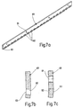
- the Stamping die formed as a metal plate, which around a in the entry area Punch openings running centrally along the bend edge is bent while widening the punch openings. It is also advantageous if the insertion gap is on the side opposite the punch die has a scraper with openings for the punch knives to pass through, it is sufficient for guiding the punching knife when in the rest position only the longest punch knife in the associated shaft Wiper breakthrough engages.
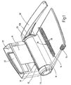
- the punching and binding machine shown in the drawing is for punching and binding sheets of different thicknesses and with different Sheet formats determined.
- the punching and binding machine includes one Punching mechanism 10 with an insertion gap 12 for those with a row of sheets 14 to be provided near the edge of the binding, a binding mechanism 16 for binding the sheet stack in the area of the binding holes by means of a not shown, elastically spreadable spine relative to the machine housing 18 between a working position and a leaf magazine 20 with measuring chamber 22, which can be pivoted to a rest position, and a measuring arrangement engaging in the measuring chamber of the sheet magazine 20 24 for the thickness measurement of the one located in the measuring chamber, not illustrated stack of sheets.
- the operating lever 30 detachable knife shaft over a partial length radially projecting receiving ribs 42 extending on the knife shaft, which form a stop step 40 for punch body 44.
- the punch body 44 have several protruding circumferentially over the receiving ribs 42 and punch knives 46 spaced axially apart on, which carry a cutting edge 48 on their front side.
- the punch body 44 with the punching knives 46 are coaxial to the axis 50 in the assembled state the knife shaft 28 curved.
- the individual punch blades 46 of the punch body 44 are in the circumferential direction to different degrees over the base web 45 over so that they are in different angular positions during the punching process of the operating lever 30 take effect. This will overcome those Punching forces reduced.
- the punch body 46 shown in FIGS. 6a to c has a total of seven Punching knives 46 projecting to different degrees over the base web 45 the middle punch knife is longer than the other punch knives, while the two outer die cutters are shorter than the middle one, but longer than the other die cutters. With these precautions is achieved that the moment forces acting on the punch body 44 during the punching process, which could tilt the punch body 44 with respect to the knife shaft, be reduced.
- the cutting knives have oblique cutting edges 48 on their end faces on, with partly different oblique angles, which in different Can point directions. Instead of the diagonal cutting edges In the guillotine style, concave, crescent-shaped punching edges can also be used be provided.
- the punch body 44 are not shown on the holes 52 in FIG Pin the receiving ribs 42 against displacement in the circumferential direction and fixed in the axial direction.
- On the knife shaft 28 are in the shown Embodiment also three in different axial positions Knife holder 54 located, which protrude in the circumferential direction have curved punch knives 56 and via a camshaft 58 can optionally be coupled with the knife shaft 28 in a form-fitting manner.
- the insertion gap 12 on the cutting edges 48 is the cutting knife 46 and 56 opposite side delimited by a punch die 60, the passage openings 62 arranged at equal intervals from one another for the punching knives 46, 56 and that on their insertion slot 12 opposite side open into a receptacle 64 for punching waste.
- the stamping die 60 is designed as a metal plate which extends over the fastening holes 61 is screwed to a housing-fixed part.
- the punch die is one in the entry area of the through openings 62 in the middle, running along the through openings Bending edge 63 folded to widen the punch openings.
- the insertion gap is on the flank opposite the punching die 60 12 by a scraper 65 with openings for the passage of the Stamping knife 46, 56 limited. Exactly around the flying knife to align, at least one of the punching knives 46, 56 engages in the rest position the knife shaft 28 into the associated wiper opening.
- the punching bodies 44 are concave curved, housing-fixed sliding guide 69 out.
- the sliding guide can be provided with circumferential ribs to the frictional forces to reduce.
- the actuating lever 30 is pointing upwards Starting position pivoted into the end position shown in Fig. 1.
- the punching knives 46, 56 arrive with their cutting edges 48 one after the other through the stripper 65 into the insertion gap 12 and the Passage opening 62 of the punch die 60 and in this way generate the Binding holes near the edge in the sheets 14 in the insertion gap.
- the switch blades 54 are made in accordance with the predetermined Format switched on or off. It becomes a symmetrical one Hole arrangement achieved along the edge of the hole and at the same time avoided, that side edges are punched out.
- a camshaft 58 is connected to the rotary knob 76 in a rotationally and displaceably fixed manner.
- the camshaft 58 engages in one side of the rotary knob 76 open central bore 90 of the cutter shaft 28 and points to the axial Positions of the rotatable on the knife shaft 28 about the axis 50 Knife holder 54 each have a cam curve 92.
- the camshafts 58 a via the cam curves 92 locking pin arranged in a radial opening 94 of the knife shaft 28 96 positioned radially.
- the locking pin 96 is under the influence of an Knife holder 54 is supported by spring 98, which presses it against cam cam 92 suppressed.
- the locking pin engages 96 into a blind hole 100 open to the knife shaft 28 or is made of this coughed up.
- the engaged position of the locking pin there is a positive connection of the knife holder 54 in question with the knife shaft 28, while in the disengaged position there is no positive connection and the knife holder 54 in a circumferential groove 102 of the knife shaft 28 coaxially is rotatable to axis 50 (switch-off position).
- the bottom 104 of the measuring chamber 22 a plurality of steps 118 leading to the rear contact surface 106 descend.
- this step arrangement it is possible to make a thick one Subdivide the stack of sheets so that the partial stacks are slightly above their upper Step edge can be recorded individually.
- Levels 118 are chosen so that the individual partial stacks fit into the insertion gap 12. Thereby is punching and binding thick sheet stacks that are not punched at once can be relieved.
- the invention relates to a device for punching sheet stacks, especially for a combined Punching and binding machine.
- the punching device has one side by a die 60 limited insertion slot 12 for those with a Row of punch holes to be provided near the edge 14 and one Number of along the insertion gap at defined distances from each other arranged, via an actuating lever 20 across the insertion gap 12 and the punch die 60 movable punch knives 46, 56 on.
- a particularly simple and low-friction construction is according to the Invention achieved in that a plurality of punch knives 46 via a base web 45 integrally connected to form a punch 44 are that at least one of the punch body 44 with one above the Actuating lever 30 knife shaft 28 rotatable about a central axis 30 is detachably coupled and curved coaxially to the central axis, and that the Punching body at least on its punching knives pointing in the circumferential direction 46 has a radial distance from the cutter shaft 28.
Landscapes
- Engineering & Computer Science (AREA)
- Life Sciences & Earth Sciences (AREA)
- Forests & Forestry (AREA)
- Mechanical Engineering (AREA)
- Textile Engineering (AREA)
- Perforating, Stamping-Out Or Severing By Means Other Than Cutting (AREA)
Description
- Fig. 1
- eine schaubildliche Darstellung einer kombinierten Stanz- und Bindemaschine in aufgeklapptem Zustand;
- Fig. 2a und b
- einen Längsschnitt durch die Stanz- und Bindemaschine nach Fig. 1 in schaubildlicher Darstellung mit und ohne Messerwelle;
- Fig. 3
- einen Längsschnitt durch die Stanz- und Bindemaschine nach Fig. 1;
- Fig. 4a
- eine schaubildliche Explosionsdarstellung der Messerwelle mit Stanzmessem und Nockenwelle für die Ansteuerung der Schaltmesser;
- Fig. 4b
- eine schaubildliche Ansicht der Messerwelle im montierten Zustand;
- Fig. 5a
- eine Stimseitenansicht der Messerwelle mit Nockenwelle und Schaltmesser;
- Fig. 5b und c
- einen Schnitt durch die Messerwelle bei gekuppeltem und entkuppeltem Schaltmesser;
- Fig. 6a
- ein Stanzkörper mit sieben Stanzmessem in schaubildlicher Darstellung;
- Fig. 6b und c
- eine Breitseitenansicht und eine Stirnseitenansicht des Stanzkörpers nach Fig. 6a in vergrößerter Darstellung;
- Fig. 7a
- eine schaubildliche Darstellung der Stanzmatrize;
- Fig. 7b und c
- zwei senkrechte Schnitte durch die Stanzmatrize im Bereich der Stanzlöcher und der Befestigungslöcher.
Claims (27)
- Vorrichtung zum Stanzen von Blattstapeln, insbesondere für eine kombinierte Stanz- und Bindemaschine, mit einem einseitig durch eine Stanzmatrize (60) begrenzten Einschubspalt (12) für die mit einer Reihe von randnahen Stanzlöchern zu versehenden Blätter (14) des Blattstapels und mit einer Anzahl von entlang dem Einschubspalt (12) in definierten Abständen voneinander angeordneten, über ein Betätigungsorgan (30) quer durch den Einschubspalt (12) und die Stanzmatrize (60) hindurch bewegbaren Stanzmessem (46, 56), dadurch gekennzeichnet, daß mehrere Stanzmesser (46) über einen Basissteg (45) unter Bildung eines Stanzkörpers (44) einstückig miteinander verbunden sind, daß mindestens einer der Stanzkörper (44) mit einer über das Betätigungsorgan (30) um eine Zentralachse (50) drehbaren Messerwelle (28) lösbar gekuppelt und koaxial zur Zentralachse (50) gekrümmt ist und zumindest an seinen in Umfangsrichtung weisenden Stanzmessern (46) einen radialen Abstand von der Messerwelle (28) aufweist.
- Vorrichtung nach Anspruch 1, dadurch gekennzeichnet, daß an der Messerwelle (28) eine radial überstehende langgestreckte Aufnahmerippe (42) für den mindestens einen Stanzkörper (44) angeordnet ist.
- Vorrichtung nach Anspruch 1 oder 2, dadurch gekennzeichnet, daß der mindestens eine Stanzkörper (44) im Bereich seines Basisstegs (45) mindestens zwei im Abstand voneinander angeordnete Durchbrüche (52) zur Aufnahme von an der Messerwelle (28) radial überstehenden Haltezapfen aufweist.
- Vorrichtung nach einem der Ansprüche 1 bis 3, dadurch gekennzeichnet, daß die Aufnahmerippe (42) eine in Umfangsrichtung weisende, radial über die Messerwelle überstehende Anschlagstufe (41) aufweist, gegen die der mindestens eine Stanzkörper (44) im montierten Zustand mit der freien Rückkante seines Basisstegs (45) anliegt.
- Vorrichtung nach einem der Ansprüche 1 bis 4, dadurch gekennzeichnet, daß zumindest ein Teil der Stanzmesser (46) an ihren Stirnseiten schräge Stanzschneiden (48) aufweisen.
- Vorrichtung nach Anspruch 5, dadurch gekennzeichnet, daß mindestens zwei der Stanzschneiden (48) in Stanzrichtung gesehen unterschiedliche Schrägwinkel aufweisen.
- Vorrichtung nach Anspruch 5 oder 6, dadurch gekennzeichnet, daß mindestens zwei der Stanzschneiden (48) in Stanzrichtung gesehen nach entgegengesetzten Seiten schräg angestellt sind.
- Vorrichtung nach einem der Ansprüche 5 bis 7, dadurch gekennzeichnet, daß mindestens eine der Stanzschneiden quer zur Stanzrichtung ausgerichtet ist.
- Vorrichtung nach einem der Ansprüche 1 bis 8, dadurch gekennzeichnet, daß mindestens eines der Stanzmesser (46) an seiner Stirnseite eine konkav gekrümmte Stanzschneide (48) aufweist.
- Vorrichtung nach einem der Ansprüche 1 bis 9, dadurch gekennzeichnet, daß die Stanzmesser (46) innerhalb des Stanzkörpers (44) unterschiedlich weit über den Basissteg (45) überstehen.
- Vorrichtung nach Anspruch 10, dadurch gekennzeichnet, daß der Stanzkörper (44) eine ungerade Anzahl Stanzmesser (46) aufweist.
- Vorrichtung nach Anspruch 10 oder 11, dadurch gekennzeichnet, daß das mittlere Stanzmesser (46) des Stanzkörpers (44) länger als die übrigen Stanzmesser ist.
- Vorrichtung nach einem der Ansprüche 10 bis 12, dadurch gekennzeichnet, daß die beiden äußeren Stanzmesser (46) eines Stanzkörpers (44) kürzer als das mittlere, aber länger als die übrigen Stanzmesser sind.
- Vorrichtung nach einem der Ansprüche 1 bis 13, dadurch gekennzeichnet, daß mindestens eines der Stanzmesser (56) einzeln an einem Messerhalter (54) angeordnet ist, der mit einer über das Betätigungsorgan (30) um eine Zentralachse (50) drehbaren Messerwelle (28) kuppelbar ist, wobei das in Umfangsrichtung der Messerwelle (28) weisende Stanzmesser (56) koaxial zur Zentralachse (50) gekrümmt ist und einen radialen Abstand von der Messerwelle (28) aufweist.
- Vorrichtung zum Stanzen von Blattstapeln, insbesondere für eine kombinierte Stanz- und Bindemaschine, mit einem einseitig durch eine Stanzmatrize (60) begrenzten Einschubspalt (12) für die mit einer Reihe von randnahen Stanzlöchern zu versehenden Blätter (14) des Blattstapels und mit einer Anzahl von entlang dem Einschubspalt (12) in definierten Abständen voneinander angeordneten, über ein Betätigungsorgan (30) quer durch den Einschubspalt (12) und die Stanzmatrize (60) hindurch bewegbaren Stanzmessem (46, 56), dadurch gekennzeichnet, daß mindestens eines der Stanzmesser (56) einzeln an einem Messerhalter (54) angeordnet ist, der mit einer über das Betätigungsorgan (30) um eine Zentralachse (50) drehbaren Messerwelle (28) kuppelbar ist, wobei das in Umfangsrichtung der Messerwelle (28) weisende Stanzmesser (56) koaxial zur Zentralachse (50) gekrümmt ist und einen radialen Abstand von der Messerwelle (28) aufweist.
- Vorrichtung nach Anspruch 14 oder 15, dadurch gekennzeichnet, daß der Messerhalter (54) axial unverschiebbar und in Umfangsrichtung wahlweise verdrehbar oder über einen Kupplungsmechanismus (92, 96) arretierbar auf der Messerwelle (28) angeordnet ist.
- Vorrichtung nach Anspruch 16, dadurch gekennzeichnet, daß der Kupplungsmechanismus eine Nockenwelle (58) mit je einer den einzelnen Messerhaltern (54) zugeordneten Nockenkurve (92) sowie je ein über die zugehörige Nockenkurve radial verstellbares Sperrorgan (96) aufweist.
- Vorrichtung nach Anspruch 17, dadurch gekennzeichnet, daß die Nockenwelle (58) in eine Zentralbohrung (90) der Messerwelle (28) eingreift und gegenüber dieser verdrehbar ist.
- Vorrichtung nach Anspruch 17 oder 18, dadurch gekennzeichnet, daß das Sperrorgan (96) durch einen radialen Durchbruch (94) in der Messerwelle (28) hindurchgreift, wobei es in der Arretierungsstellung unter der Einwirkung der Nockenkurve (92) in eine zur radial innen liegenden Messerwelle (28) hin offene Radialbohrung (100) des Messerhalters (54) eingreift und in der Abschaltstellung aus der Radialbohrung in Richtung Messerwelle herausgedrängt ist.
- Vorrichtung nach einem der Ansprüche 17 bis 19, dadurch gekennzeichnet, daß das Sperrorgan (96) unter der Einwirkung einer in Richtung Nockenwelle (58) weisenden Kraft einer im Messerhalter (54) abgestützten Feder (98) steht.
- Vorrichtung nach einem der Ansprüche 1 bis 20, dadurch gekennzeichnet, daß die Messerwelle (28) drehfest mit einem das Betätigungsorgan bildenden Betätigungshebel (30) verbunden ist.
- Vorrichtung nach einem der Ansprüche 1 bis 20, dadurch gekennzeichnet, daß die Messerwelle (28) motorisch antreibbar ist.
- Vorrichtung nach einem der Ansprüche 1 bis 22, dadurch gekennzeichnet, daß die Stanzmesser (46, 56) mit ihrer konkaven Außenfläche (67) in einer gehäusefesten, konkav gekrümmten Gleitführung (69) geführt sind.
- Vorrichtung nach einem der Ansprüche 1 bis 23, dadurch gekennzeichnet, daß die Durchtrittsöffnungen (62) der Stanzmatrize (60) einen von der Eintrittsseite zur Austrittsseite hin variablen Querschnitt aufweisen.
- Vorrichtung nach Anspruch 24, dadurch gekennzeichnet, daß die Stanzmatrize (60) als Metallplatte ausgebildet ist, die eine im Eintrittsbereich der Durchtrittsöffnungen (62) mittig entlang den Durchtrittsöffnungen (62) verlaufenden Biegekante (63) unter Aufweitung der Durchtrittsöffnungen abgekantet ist.
- Vorrichtung nach einem der Ansprüche 1 bis 25, dadurch gekennzeichnet, daß der Einschubspalt (12) auf der der Stanzmatrize (60) gegenüberliegenden Seite einen Abstreifer (65) mit Durchbrüchen für den Durchgriff der Stanzmesser (46, 56) aufweist.
- Vorrichtung nach Anspruch 26, dadurch gekennzeichnet, daß in der Ruhestellung der Messerwelle (28) nur das jeweils längste Stanzmesser (46, 56) in den zugehörigen Abstreifer-Durchbruch eingreift.
Applications Claiming Priority (3)
| Application Number | Priority Date | Filing Date | Title |
|---|---|---|---|
| DE19947256 | 1999-09-30 | ||
| DE19947256A DE19947256A1 (de) | 1999-09-30 | 1999-09-30 | Stanzvorrichtung für Blattstapel |
| PCT/EP2000/007219 WO2001023191A1 (de) | 1999-09-30 | 2000-07-27 | Stanzvorrichtung für blattstapel |
Publications (2)
| Publication Number | Publication Date |
|---|---|
| EP1216157A1 EP1216157A1 (de) | 2002-06-26 |
| EP1216157B1 true EP1216157B1 (de) | 2003-05-28 |
Family
ID=7924116
Family Applications (1)
| Application Number | Title | Priority Date | Filing Date |
|---|---|---|---|
| EP00956309A Expired - Lifetime EP1216157B1 (de) | 1999-09-30 | 2000-07-27 | Stanzvorrichtung für blattstapel |
Country Status (7)
| Country | Link |
|---|---|
| EP (1) | EP1216157B1 (de) |
| CN (1) | CN1358141A (de) |
| AT (1) | ATE241478T1 (de) |
| AU (1) | AU6829900A (de) |
| DE (2) | DE19947256A1 (de) |
| HK (1) | HK1043567A1 (de) |
| WO (1) | WO2001023191A1 (de) |
Families Citing this family (4)
| Publication number | Priority date | Publication date | Assignee | Title |
|---|---|---|---|---|
| US8434987B2 (en) | 2009-12-23 | 2013-05-07 | ACCO Brands Corporation | Binding machine |
| CN105216051B (zh) * | 2013-03-25 | 2016-11-30 | 兰如林 | 适用在布料、皮料以及革料上的打孔机 |
| CN105459200A (zh) * | 2015-11-16 | 2016-04-06 | 上海应用技术学院 | 折纸和打孔一体化装置 |
| CN114932597B (zh) * | 2022-06-15 | 2023-08-25 | 中鼎星模具(苏州)有限公司 | 一种数控激光刀模冲片机装置 |
Family Cites Families (3)
| Publication number | Priority date | Publication date | Assignee | Title |
|---|---|---|---|---|
| GB2293128B (en) * | 1992-05-27 | 1996-06-12 | Acco Rexel Group Services Plc | Punching devices |
| EP0864440A1 (de) * | 1997-03-13 | 1998-09-16 | Ibico Ag | Stanzeinheit |
| DE19856702A1 (de) * | 1998-12-09 | 2000-06-21 | Esselte Nv | Stanzvorrichtung |
-
1999
- 1999-09-30 DE DE19947256A patent/DE19947256A1/de not_active Withdrawn
-
2000
- 2000-07-27 WO PCT/EP2000/007219 patent/WO2001023191A1/de active IP Right Grant
- 2000-07-27 DE DE50002388T patent/DE50002388D1/de not_active Expired - Fee Related
- 2000-07-27 EP EP00956309A patent/EP1216157B1/de not_active Expired - Lifetime
- 2000-07-27 AU AU68299/00A patent/AU6829900A/en not_active Abandoned
- 2000-07-27 AT AT00956309T patent/ATE241478T1/de not_active IP Right Cessation
- 2000-07-27 CN CN00809534A patent/CN1358141A/zh active Pending
-
2002
- 2002-07-16 HK HK02105229.0A patent/HK1043567A1/zh unknown
Also Published As
| Publication number | Publication date |
|---|---|
| WO2001023191A1 (de) | 2001-04-05 |
| DE50002388D1 (de) | 2003-07-03 |
| HK1043567A1 (zh) | 2002-09-20 |
| DE19947256A1 (de) | 2001-04-05 |
| CN1358141A (zh) | 2002-07-10 |
| ATE241478T1 (de) | 2003-06-15 |
| AU6829900A (en) | 2001-04-30 |
| EP1216157A1 (de) | 2002-06-26 |
Similar Documents
| Publication | Publication Date | Title |
|---|---|---|
| EP0077932B1 (de) | Vorrichtung zum nietartigen Verbinden von Blechen | |
| DE3133029A1 (de) | Haltevorrichtung fuer einen schneidwerkzeugeinsatz | |
| DE202004004422U1 (de) | Messer mit austauschbarer Klinge | |
| DE3211766A1 (de) | Schlitzschneider | |
| EP1711288B1 (de) | Fügeeinrichtung | |
| EP3144076B1 (de) | Werkzeug für eine stanzmaschine zum umformen von abschnitten eines plattenförmigen werkstücks und verfahren dazu | |
| DE202010007124U1 (de) | Blockschneider mit verbesserter Nockenhebelkraft | |
| EP0195120B1 (de) | Vorrichtung zum Schneiden von Tapeten | |
| EP1216157B1 (de) | Stanzvorrichtung für blattstapel | |
| DE102010007917B4 (de) | Handbetätigtes Werkzeug | |
| DE4190357C2 (de) | Feilschablone für das Feilen von Sägeketten | |
| DE2850811C2 (de) | Rotierende Schneideinheit für ein Trockenrasiergerät | |
| EP2357053B1 (de) | Feilenführung | |
| EP1470951B1 (de) | Ratschenartige Verstellvorrichtung | |
| EP0267312B1 (de) | Kraftgetriebene Säge, insbesondere elektromotorisch angetriebene Säge | |
| DE102008003419B4 (de) | Stanzeinheit für eine Stanz- und Bindevorrichtung sowie Stanz- und Bindevorrichtung | |
| WO2001023192A1 (de) | Stanz- und bindemaschine | |
| EP0088990A2 (de) | Messerträger eines Hobelmessers | |
| DE3018359C2 (de) | Messerwelle zur Erzeugung flächiger Holzspäne | |
| DE102004011054B4 (de) | Ratschenartige Verstellvorrichtung | |
| DE4344129A1 (de) | Kraftgetriebene Schwertsäge | |
| DE2110046C2 (de) | Bodenteil eines Lochers für Schriftgut | |
| DE202005009010U1 (de) | Schneidendes Bürokleingerät | |
| EP0267313B1 (de) | Schwert für eine Säge mit zwei gegensinnig hin- und herbewegbaren Sägeblättern | |
| DE8312309U1 (de) | Papierhandhabungsgerät |
Legal Events
| Date | Code | Title | Description |
|---|---|---|---|
| PUAI | Public reference made under article 153(3) epc to a published international application that has entered the european phase |
Free format text: ORIGINAL CODE: 0009012 |
|
| 17P | Request for examination filed |
Effective date: 20010825 |
|
| AK | Designated contracting states |
Kind code of ref document: A1 Designated state(s): AT BE CH CY DE DK ES FI FR GB GR IE IT LI LU MC NL PT SE |
|
| GRAH | Despatch of communication of intention to grant a patent |
Free format text: ORIGINAL CODE: EPIDOS IGRA |
|
| GRAH | Despatch of communication of intention to grant a patent |
Free format text: ORIGINAL CODE: EPIDOS IGRA |
|
| GRAA | (expected) grant |
Free format text: ORIGINAL CODE: 0009210 |
|
| AK | Designated contracting states |
Designated state(s): AT BE CH CY DE DK ES FI FR GB GR IE IT LI LU MC NL PT SE |
|
| PG25 | Lapsed in a contracting state [announced via postgrant information from national office to epo] |
Ref country code: IT Free format text: LAPSE BECAUSE OF FAILURE TO SUBMIT A TRANSLATION OF THE DESCRIPTION OR TO PAY THE FEE WITHIN THE PRE;WARNING: LAPSES OF ITALIAN PATENTS WITH EFFECTIVE DATE BEFORE 2007 MAY HAVE OCCURRED AT ANY TIME BEFORE 2007. THE CORRECT EFFECTIVE DATE MAY BE DIFFERENT FROM THE ONE RECORDED.SCRIBED TIME-LIMIT Effective date: 20030528 Ref country code: IE Free format text: LAPSE BECAUSE OF FAILURE TO SUBMIT A TRANSLATION OF THE DESCRIPTION OR TO PAY THE FEE WITHIN THE PRESCRIBED TIME-LIMIT Effective date: 20030528 Ref country code: FR Free format text: LAPSE BECAUSE OF NON-PAYMENT OF DUE FEES Effective date: 20030528 Ref country code: GB Free format text: LAPSE BECAUSE OF FAILURE TO SUBMIT A TRANSLATION OF THE DESCRIPTION OR TO PAY THE FEE WITHIN THE PRESCRIBED TIME-LIMIT Effective date: 20030528 Ref country code: NL Free format text: LAPSE BECAUSE OF FAILURE TO SUBMIT A TRANSLATION OF THE DESCRIPTION OR TO PAY THE FEE WITHIN THE PRESCRIBED TIME-LIMIT Effective date: 20030528 Ref country code: FI Free format text: LAPSE BECAUSE OF FAILURE TO SUBMIT A TRANSLATION OF THE DESCRIPTION OR TO PAY THE FEE WITHIN THE PRESCRIBED TIME-LIMIT Effective date: 20030528 |
|
| REG | Reference to a national code |
Ref country code: GB Ref legal event code: FG4D Free format text: NOT ENGLISH |
|
| REG | Reference to a national code |
Ref country code: CH Ref legal event code: EP |
|
| REG | Reference to a national code |
Ref country code: IE Ref legal event code: FG4D Free format text: GERMAN |
|
| REF | Corresponds to: |
Ref document number: 50002388 Country of ref document: DE Date of ref document: 20030703 Kind code of ref document: P |
|
| PG25 | Lapsed in a contracting state [announced via postgrant information from national office to epo] |
Ref country code: AT Free format text: LAPSE BECAUSE OF NON-PAYMENT OF DUE FEES Effective date: 20030727 Ref country code: LU Free format text: LAPSE BECAUSE OF NON-PAYMENT OF DUE FEES Effective date: 20030727 Ref country code: CY Free format text: LAPSE BECAUSE OF FAILURE TO SUBMIT A TRANSLATION OF THE DESCRIPTION OR TO PAY THE FEE WITHIN THE PRESCRIBED TIME-LIMIT Effective date: 20030727 |
|
| PG25 | Lapsed in a contracting state [announced via postgrant information from national office to epo] |
Ref country code: MC Free format text: LAPSE BECAUSE OF NON-PAYMENT OF DUE FEES Effective date: 20030731 Ref country code: BE Free format text: LAPSE BECAUSE OF NON-PAYMENT OF DUE FEES Effective date: 20030731 |
|
| PG25 | Lapsed in a contracting state [announced via postgrant information from national office to epo] |
Ref country code: SE Free format text: LAPSE BECAUSE OF FAILURE TO SUBMIT A TRANSLATION OF THE DESCRIPTION OR TO PAY THE FEE WITHIN THE PRESCRIBED TIME-LIMIT Effective date: 20030828 Ref country code: DK Free format text: LAPSE BECAUSE OF FAILURE TO SUBMIT A TRANSLATION OF THE DESCRIPTION OR TO PAY THE FEE WITHIN THE PRESCRIBED TIME-LIMIT Effective date: 20030828 Ref country code: GR Free format text: LAPSE BECAUSE OF FAILURE TO SUBMIT A TRANSLATION OF THE DESCRIPTION OR TO PAY THE FEE WITHIN THE PRESCRIBED TIME-LIMIT Effective date: 20030828 Ref country code: PT Free format text: LAPSE BECAUSE OF FAILURE TO SUBMIT A TRANSLATION OF THE DESCRIPTION OR TO PAY THE FEE WITHIN THE PRESCRIBED TIME-LIMIT Effective date: 20030828 |
|
| PG25 | Lapsed in a contracting state [announced via postgrant information from national office to epo] |
Ref country code: ES Free format text: LAPSE BECAUSE OF FAILURE TO SUBMIT A TRANSLATION OF THE DESCRIPTION OR TO PAY THE FEE WITHIN THE PRESCRIBED TIME-LIMIT Effective date: 20030908 |
|
| NLV1 | Nl: lapsed or annulled due to failure to fulfill the requirements of art. 29p and 29m of the patents act | ||
| GBV | Gb: ep patent (uk) treated as always having been void in accordance with gb section 77(7)/1977 [no translation filed] |
Effective date: 20030528 |
|
| REG | Reference to a national code |
Ref country code: IE Ref legal event code: FD4D |
|
| BERE | Be: lapsed |
Owner name: *ESSELTE N.V. Effective date: 20030731 |
|
| PG25 | Lapsed in a contracting state [announced via postgrant information from national office to epo] |
Ref country code: DE Free format text: LAPSE BECAUSE OF NON-PAYMENT OF DUE FEES Effective date: 20040203 |
|
| PLBE | No opposition filed within time limit |
Free format text: ORIGINAL CODE: 0009261 |
|
| STAA | Information on the status of an ep patent application or granted ep patent |
Free format text: STATUS: NO OPPOSITION FILED WITHIN TIME LIMIT |
|
| 26N | No opposition filed |
Effective date: 20040302 |
|
| EN | Fr: translation not filed | ||
| PG25 | Lapsed in a contracting state [announced via postgrant information from national office to epo] |
Ref country code: LI Free format text: LAPSE BECAUSE OF NON-PAYMENT OF DUE FEES Effective date: 20040731 Ref country code: CH Free format text: LAPSE BECAUSE OF NON-PAYMENT OF DUE FEES Effective date: 20040731 |
|
| REG | Reference to a national code |
Ref country code: CH Ref legal event code: PL |