EP1215768B1 - Elektrischer Verbinder - Google Patents
Elektrischer Verbinder Download PDFInfo
- Publication number
- EP1215768B1 EP1215768B1 EP01129562A EP01129562A EP1215768B1 EP 1215768 B1 EP1215768 B1 EP 1215768B1 EP 01129562 A EP01129562 A EP 01129562A EP 01129562 A EP01129562 A EP 01129562A EP 1215768 B1 EP1215768 B1 EP 1215768B1
- Authority
- EP
- European Patent Office
- Prior art keywords
- article
- housing
- electric connector
- fitting
- contact
- Prior art date
- Legal status (The legal status is an assumption and is not a legal conclusion. Google has not performed a legal analysis and makes no representation as to the accuracy of the status listed.)
- Expired - Lifetime
Links
Images






Classifications
-
- H—ELECTRICITY
- H01—ELECTRIC ELEMENTS
- H01R—ELECTRICALLY-CONDUCTIVE CONNECTIONS; STRUCTURAL ASSOCIATIONS OF A PLURALITY OF MUTUALLY-INSULATED ELECTRICAL CONNECTING ELEMENTS; COUPLING DEVICES; CURRENT COLLECTORS
- H01R13/00—Details of coupling devices of the kinds covered by groups H01R12/70 or H01R24/00 - H01R33/00
- H01R13/02—Contact members
- H01R13/22—Contacts for co-operating by abutting
- H01R13/24—Contacts for co-operating by abutting resilient; resiliently-mounted
- H01R13/2442—Contacts for co-operating by abutting resilient; resiliently-mounted with a single cantilevered beam
-
- H—ELECTRICITY
- H01—ELECTRIC ELEMENTS
- H01R—ELECTRICALLY-CONDUCTIVE CONNECTIONS; STRUCTURAL ASSOCIATIONS OF A PLURALITY OF MUTUALLY-INSULATED ELECTRICAL CONNECTING ELEMENTS; COUPLING DEVICES; CURRENT COLLECTORS
- H01R13/00—Details of coupling devices of the kinds covered by groups H01R12/70 or H01R24/00 - H01R33/00
- H01R13/40—Securing contact members in or to a base or case; Insulating of contact members
- H01R13/42—Securing in a demountable manner
- H01R13/436—Securing a plurality of contact members by one locking piece or operation
Definitions
- the present invention belongs to a field of electric connectors, which are used to electrically connect two articles that are exemplified by printed circuit board, electrical part, etc.
- the present inventor contemplated to reduce the number of electric connector to be used in a connecting structure to one by, when an electric wire is led out of the first article, fitting an electric connector, which is connected to the electric wire by crimping or insulation displacement connection, onto the first article and/or the second article and making a contact of this electric connector directly contact a conductive part of the second article, and in turn, to reduce the costs of the connecting structure and compactify it.
- the present invention is an electric connector according to claim 1.
- the electric connector of the present invention ensures a contact pressure at the contacting point and makes a reliable electric connection between the articles, reduces the number of electric connector in use and improves the workability, and in turn, achieves significant cost reduction and compactification of the connecting structure. Even if the electric wire is subjected to a pulling and moving force and is bent towards the receiving groove, the electric wire will be held by the retainer. Thus the electric wire or the wired contact is reliably prevented from coming off the housing. When the housing is fitted onto both the first article and the second article, the costs can be reduced through elimination of a joining means.
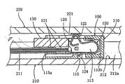
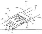
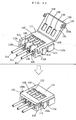
- Fig. 1 through Fig. 3 show the first electric connector 100
- This electric connector 100 is used to electrically connect the electric wire of the first article to the conductive part of the second article.
- the first article 210 is exemplified by a casing of an electric appliance, and this first article 210 has the electric wire 211.
- the second article 220 is exemplified by a printed circuit board, and the conductive part 221 of the second article 220 is exemplified by a conductive pad.
- the concepts of the articles and the concepts of the conductive parts according to the present invention are not limited in any way by these exemplifications.
- the articles may be any corporeal things, and the conductive parts may be any members having electric conductivity.
- the above-mentioned electric connector 100 comprises a housing 110, which is fitted onto the first article 210, a contact 120, which is inserted into and fitted onto a receiving groove of the housing 110, and a retainer 130, which is fitted onto the housing 110.
- the housing 110 is formed approximately into a rectangular parallelepiped.
- a direction along one side of the housing 110 is defined as the longitudinal direction
- a direction that is approximately perpendicular to that direction is defined as the width direction
- a direction that is approximately perpendicular to both the longitudinal direction and the width direction is defined as the height direction.
- the housing 110 has a front face 111, which faces the conductive part 221 of the second article 220 when the electric wire 211 of the first article 210 is electrically connected to the conductive part 221 of the second article 220 via the electric connector 100, and side faces, which extends from the peripheral of the front face 111 in the height direction. Since the housing 110 is approximately a rectangular parallelepiped, it has side faces 112a, 112b, which are on both ends in the longitudinal direction, and side faces 112c, 112d, which are on both ends in the width direction.
- the housing 110 is provided with a receiving groove 113, which is concaved from the front face 111 and extends in the longitudinal direction.
- One end 113a of this receiving groove 113 extends to and opens in one side face 112a.
- the receiving groove 113 has an open side end 113a and a closed side end 113b, and the receiving groove 113 acquires a directionality that is determined by the open side and the closed side.
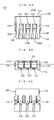
- the same number of receiving grooves 113 as the contacts 120 are formed in a row in the width direction.
- a fitting groove 114 extending in the height direction is formed in the side faces 112c, 112d on both ends in the width direction of the housing 110, into which a guide protrusion that will be described below of the first article 210 is fitted.
- the housing according to the present invention is not limited to the form of the approximate rectangular parallelepiped. It may be any form, which can be fitted onto one article and into which the contacts can be assembled.
- the above-mentioned contact 120 is made of a member that has electric conductivity.
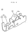
- the contact 120 comprises a connecting part 121, which is connected to the conductive part 211 of the first article 210, and a contacting part 122, which contacts the conductive part 221 of the second article 220.
- the contacting part 122 is arranged closer to the closed side of the receiving groove 113 than the connecting part 121.
- the contact 120 is inserted into the receiving groove 113 from the open side thereof. In this embodiment, it is exemplified by a crimp type contact 120.
- the connecting part 121 is a barrel formed on the contact 120, and this barrel comprises a wire barrel 121a, which crimps the core of the electric wire 211, and an insulation barrel 121b, which crimps this electric wire together with its insulation.
- the contacting part 122 is made of an oblong rectangle material, which is curved to form a U-shape when seen in the width direction and function as a leaf spring, which is flexible in the height direction. When necessary, the top end of the contacting part 122 is bent into an inverted-U shape, when seen in the width direction, to form a contacting point, and this contacting point comes out of the receiving groove 113 of the housing 110 and the front face 111 thereof.
- the configuration of the contact is not limited by this embodiment.
- the contact may be bent into, for example, an L shape without any curving.
- a dimple 122a is formed in this contacting part 122 by embossing or the like to define a contacting point for the conductive part 221 of the second article 220.
- a fitting structure with the so-called contact lance is used.
- the contact 120 is provided with a protruding piece 124, and this protruding piece 124 is used as a lance to be fitted into a fitting window 115 that is opened in the receiving groove 113 of the housing 110.
- a fitting structure with the so-called housing lance may be used.
- the housing is provided with a protruding piece and this protruding piece is fitted into a fitting window of the contact.
- the contact may be fitted into the housing without using any lance.
- the retainer 130 is fitted onto the housing 110, the retainer 130 covering at least the open-side ends 113a of the receiving grooves 113.
- the retainer 130 comprises covers 131, which fit into the receiving grooves 113, and arms 132, which fit onto the housing 110.
- the cover 131 is formed into a comb so that it can fit into the respective receiving grooves 113.
- the arm 132 is formed into an L shape, and one end of the arm 132 is connected to the cover 131 and the arm 132 extends along the side face of the housing 110.
- the above-mentioned housing 110 is fitted onto an article by fitting itself into a concaved part formed in the article.
- the housing 110 is fitted onto the first article 210.
- a groove-shaped concaved part 212 is formed in the first article 210, and the width of the housing 110 is made to have a dimension that can fit into this concaved part 212.
- the electric connector 100 is fitted into this concaved part 212 in such a way that the height direction of the electric connector 100 aligns with the depth direction of the concaved part 212 and the contacting part 122 comes out of the concaved part 212.
- guide protrusions may be formed on the electric connector and fitting grooves may be formed in the concaved part.
- the concaved part 212 is groove-shaped but the concaved part may have any form provided that it can store the electric connector.
- the side faces of the housing may be made to face-contact the longitudinal walls of the concaved part and the housing may be fitted onto the first article by this fitting.
- the connecting part 121 of the contact 120 of this electric connector 100 is connected to the electric wire 211 of the first article 210 by crimping. Then the contact 120 is inserted into and fitted onto the receiving groove 113 of the housing 110. Then the retainer 130 is fitted onto the housing 110.
- the present invention includes any forms of structure for fitting the housing of the electric connector onto an article.
- the housing 110 is formed to be fitted into the concaved part 212 of the article 210 and/or the concaved part 225 of the article 220 and the housing 110 is formed to be fitted onto the article 210 and/or the article 220 by this fitting-in, fitting the electric connector 100 into the concaved part 212 of the article 210 and/or the concaved part 225 of the article 220 will fit the electric connector 100 onto the article 210 and/or the article 220. Hence the workability of fitting is improved.
- the cover 131 is rotated in a direction to move away from the front face 111 of the housing 110, then contacts 120, which have been crimp-connected to electric wires 211 of the first article 210, are inserted into the receiving grooves 113 of the housing 110.
- the cover 131 is rotated to cover the front face 111 of the housing 110.
- the retainer 130 is fitted onto the housing 110 by the fitting between the fitting pawls 116 and the fitting concaved parts 132a.
- the retainer 130 can be easily fitted on the housing 110 with a single touch, and moreover, as the retainer 130 is joined to the housing 110, the number of parts is reduced and this is advantageous from the viewpoint of management.
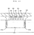
- Fig. 12 and Fig. 13 show a second electric connector 100.
- the housing 110 of this second electric connector 100 is formed in such a way that it can be inserted into a concaved part formed in an article and is provided with wings 117, which are elastically deformed to press against the longitudinal walls of a concaved part when the housing 110 is inserted into the concaved part.
- the housing 110 is fitted onto the article by the pressures of the wings 117.
- a wing 117 is provided on each of two side faces 112c, 112d on both ends, in the width direction, of the housing 110.
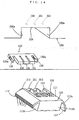
- the fitting form of the retainer 130 onto the housing 110 may be any form of the first connector and the embodiment of the invention. In the case of the connecting form shown in Fig.
- the electric connector 100 is fitted into this concaved part 225 in such a way that the height direction of the electric connector 100 aligns with the depth direction of the concaved part 225 and the contacting part 122 opposes to the bottom of the concaved part 225.
- the method of electrically connecting the articles 210, 220 with the electric connector 100 in this connecting form is similar to that of the connecting form shown in Fig. 8 and Fig. 9.
- Fig. 15 shows the electric connector 100 of the fourth embodiment.
- the housing 110 is provided with locking pawls 118, and the housing 100 is fitted onto an article by fitting the locking pawls 118 onto the article.
- the locking pawls 118 extend on both ends, in the width direction, of the housing 110 in the height direction.
- a hook 118a is provided on the top end of each locking pawl 118, and this hook 118a enters a locking hole formed in an article and hooks on the edge of the locking hole.
- the fitting form of the retainer 130 onto the housing 110 may be any fitting form of the first embodiment and the second embodiment. In the case of the connecting form shown in Fig.
- Fig. 19 shows the fifth embodiment.
- the fifth embodiment is applicable to any of the above-mentioned embodiments.
- the electric connector 100 of this fifth embodiment differs from the electric connectors 100 of the first embodiment through the fourth embodiment in that the contact 120 is of the insulation displacement connection type, and is identical to them in other aspects of the construction.
- the connecting part 121 is a slot that is formed in one end, in the longitudinal direction, of the contact 120. The core of the electric wire 211 of the first article 210 is connected into this slot by insulation displacement connection.
- the wired electric connector 100 is fitted onto the first article 210 and/or the second article 220, and the contacting part 122 of the contact 120 is made to contact the conductive part 221 of the second article 220 with a pressing force, the electric wire 211 of the first article 210 will be electrically connected to the conductive part 221 of the second article 220 via the contact 120.
Landscapes
- Connector Housings Or Holding Contact Members (AREA)
- Details Of Connecting Devices For Male And Female Coupling (AREA)
- Connections By Means Of Piercing Elements, Nuts, Or Screws (AREA)
Claims (1)
- Elektrisches Anschlussstück (100) zum elektrischen Verbinden eines elektrischen Drahts (211) eines ersten Gegenstands (210) mit einem leitenden Teil (221) eines zweiten Gegenstands (220), wobei das elektrische Anschlussstück (100) folgendes aufweist:ein Gehäuse (110), das an wenigstens einem der Gegenstände (210), (220) anzubringen ist und mit einer Aufnahmenut (113) versehen ist, die von der Vorderseite (111) aus konkav ist, die im angeschlossenen Zustand dem leitenden Teil (221) des zweiten Gegenstands (220) gegenüberliegt, und an einem Ende in einer Seitenfläche offen ist,einen Kontakt (120), der in die Aufnahmenut (113) eingefügt und an dieser angebracht ist und versehen ist mit einem Verbindungsteil (121), um durch eine Quetsch- oder eine Isolierungsablösungs-Verbindung mit dem elektrischen Draht (211) des ersten Gegenstands (210) verbunden zu werden, und einem Kontaktierungsteil (122), der zum Kontaktieren des leitenden Teils (221) des zweiten Gegenstands (220) dient, undeine Halterung (130), die wenigstens das Ende der Aufnahmenut (113) an der offenen Seite abdeckt und an das Gehäuse (110) angebracht ist, wobei die Halterung (130) eine plattenförmige Abdeckung (131) aufweist, die die Vorderseite des Gehäuses (110) abdeckt,dadurch gekennzeichnet, dass der Kontaktierungsteil näher zur geschlossenen Seite der Aufnahmenut (113) als der Verbindungsteil (121) in der Aufnahmenut (113) angeordnet ist, und dass die plattenförmige Abdeckung mit dem Gehäuse (110) an seinem einen Ende drehbar verbunden ist und in ihr ein Fenster (136) ausgebildet ist, um zuzulassen, dass der Kontaktierungsteil (122) des Kontakts (120) herauskommt, und ein Arm (132) zum Anbringen der Abdeckung (131) an dem Gehäuse (110) vorgesehen ist.
Applications Claiming Priority (2)
| Application Number | Priority Date | Filing Date | Title |
|---|---|---|---|
| JP2000384529 | 2000-12-18 | ||
| JP2000384529A JP2002184507A (ja) | 2000-12-18 | 2000-12-18 | 電気コネクタ |
Publications (3)
| Publication Number | Publication Date |
|---|---|
| EP1215768A2 EP1215768A2 (de) | 2002-06-19 |
| EP1215768A3 EP1215768A3 (de) | 2005-04-20 |
| EP1215768B1 true EP1215768B1 (de) | 2006-07-26 |
Family
ID=18851957
Family Applications (1)
| Application Number | Title | Priority Date | Filing Date |
|---|---|---|---|
| EP01129562A Expired - Lifetime EP1215768B1 (de) | 2000-12-18 | 2001-12-11 | Elektrischer Verbinder |
Country Status (8)
| Country | Link |
|---|---|
| US (1) | US6589082B2 (de) |
| EP (1) | EP1215768B1 (de) |
| JP (1) | JP2002184507A (de) |
| KR (1) | KR20020048872A (de) |
| CN (1) | CN1255903C (de) |
| DE (1) | DE60121709D1 (de) |
| HK (1) | HK1046781B (de) |
| TW (1) | TW536857B (de) |
Families Citing this family (20)
| Publication number | Priority date | Publication date | Assignee | Title |
|---|---|---|---|---|
| JP4214501B2 (ja) * | 2000-12-18 | 2009-01-28 | 日本圧着端子製造株式会社 | 電気コネクタ |
| JP2002184502A (ja) | 2000-12-18 | 2002-06-28 | Jst Mfg Co Ltd | 電気コネクタ |
| CN100495821C (zh) * | 2002-11-28 | 2009-06-03 | 旭硝子株式会社 | 形成在玻璃面上的导体用的电气连接结构 |
| US7004791B2 (en) * | 2003-10-16 | 2006-02-28 | Tyco Electronics Amp Gmbh | Contact housing and process for making a contact housing |
| CN2706895Y (zh) * | 2004-05-21 | 2005-06-29 | 富士康(昆山)电脑接插件有限公司 | 电连接器 |
| EP1737084A3 (de) * | 2005-06-21 | 2007-02-21 | Ideal Industries Inc. | Elektrischer Verbinder mit Einschubklemmkontakten |
| US7527509B1 (en) | 2005-06-21 | 2009-05-05 | Ideal Industries, Inc. | Electrical disconnect with push-in connectors |
| US7727002B2 (en) * | 2006-06-21 | 2010-06-01 | Ideal Industries, Inc. | Electrical disconnect with adjacent wire receptacle boxes |
| JP4793471B2 (ja) * | 2009-05-19 | 2011-10-12 | ヒロセ電機株式会社 | 分離可能なコネクタ |
| DE102011005542A1 (de) * | 2011-03-15 | 2012-09-20 | Robert Bosch Gmbh | Elektrische Anordnung |
| CN102801030B (zh) * | 2011-05-23 | 2015-04-01 | 富士康(昆山)电脑接插件有限公司 | 线缆连接器 |
| DE102011076962A1 (de) * | 2011-06-06 | 2012-12-06 | Robert Bosch Gmbh | Direktsteckelement, insbesondere für ein Fahrzeugsteuergerät |
| DE102012100815B3 (de) * | 2012-02-01 | 2013-01-24 | Harting Electric Gmbh & Co. Kg | Elektrisches Kupplungselement |
| JP5952626B2 (ja) * | 2012-04-19 | 2016-07-13 | 矢崎総業株式会社 | 基板コネクタ |
| JP5947640B2 (ja) * | 2012-07-03 | 2016-07-06 | 矢崎総業株式会社 | 端子金具と基板の接続構造 |
| JP6016126B2 (ja) * | 2013-08-07 | 2016-10-26 | 住友電装株式会社 | 電熱線端子への給電線配索構造 |
| JP2015207353A (ja) * | 2014-04-17 | 2015-11-19 | Smk株式会社 | 電線用コネクタ |
| JP5896009B1 (ja) * | 2014-12-12 | 2016-03-30 | 第一精工株式会社 | コネクタ端子 |
| JP6350876B2 (ja) * | 2015-06-18 | 2018-07-04 | 株式会社オートネットワーク技術研究所 | コネクタ |
| JP7195610B2 (ja) * | 2019-04-25 | 2022-12-26 | 北川工業株式会社 | 接触部材 |
Family Cites Families (20)
| Publication number | Priority date | Publication date | Assignee | Title |
|---|---|---|---|---|
| US3680035A (en) * | 1970-02-25 | 1972-07-25 | Amp Inc | Pcb hinged pod connector |
| FR2497007A1 (fr) * | 1980-12-23 | 1982-06-25 | Labinal | Perfectionnements aux boitiers de connexions electriques et aux organes de connexion destines a equiper de tels boitiers |
| JPH0665092B2 (ja) * | 1989-06-27 | 1994-08-22 | 矢崎総業株式会社 | コネクタ |
| JP2535607Y2 (ja) * | 1991-10-18 | 1997-05-14 | 矢崎総業株式会社 | コネクタ |
| JPH0575981U (ja) * | 1992-03-18 | 1993-10-15 | 矢崎総業株式会社 | ガラス板用コネクタ |
| JP2611081B2 (ja) * | 1992-03-30 | 1997-05-21 | 矢崎総業株式会社 | コネクタの端子係止構造 |
| JP3106282B2 (ja) * | 1995-04-13 | 2000-11-06 | 矢崎総業株式会社 | コネクタ |
| FR2737352B1 (fr) * | 1995-07-28 | 1997-08-29 | Itt Composants Instr | Connecteur electrique pour le raccordement d'une carte a circuit(s) integre(s) a contact |
| JPH09306576A (ja) | 1996-05-08 | 1997-11-28 | Thomas & Betts Corp <T&B> | バッテリィ用端子 |
| JPH09320672A (ja) * | 1996-05-29 | 1997-12-12 | Yazaki Corp | コネクタ |
| BR9802812A (pt) | 1997-08-29 | 1999-11-03 | Whitaker Corp | terminal para curto-circuito e conector. |
| JP3463856B2 (ja) * | 1998-03-05 | 2003-11-05 | 矢崎総業株式会社 | コネクタ接続構造 |
| JP3598811B2 (ja) | 1998-05-14 | 2004-12-08 | 住友電装株式会社 | 短絡端子とこれを組み込んだ嵌合検知用コネクタ |
| US5980322A (en) | 1998-09-01 | 1999-11-09 | 3Com Corporation | Electrical connector having a fusible link for use between media connectors and computer communications cards |
| JP2000231961A (ja) * | 1998-12-08 | 2000-08-22 | Sumitomo Wiring Syst Ltd | コネクタ |
| US6102722A (en) | 1998-12-28 | 2000-08-15 | Lucent Technologies Inc. | Upgradeable communication connector |
| US6217396B1 (en) | 1999-07-06 | 2001-04-17 | Hon Hai Precision Ind. Co., Ltd. | Electrical connector with U-shaped spring contacts |
| US6099356A (en) * | 1999-07-19 | 2000-08-08 | Hon Hai Precision Ind. Co., Ltd. | Compression connector |
| JP3534393B2 (ja) | 2000-04-14 | 2004-06-07 | インターナショナル・ビジネス・マシーンズ・コーポレーション | 電子部品ユニットの電気的接続構造、コンピュータ装置及び電子機器 |
| JP2002033154A (ja) * | 2000-07-17 | 2002-01-31 | Yazaki Corp | ジョイントコネクタ |
-
2000
- 2000-12-18 JP JP2000384529A patent/JP2002184507A/ja active Pending
-
2001
- 2001-12-03 TW TW090129859A patent/TW536857B/zh not_active IP Right Cessation
- 2001-12-11 DE DE60121709T patent/DE60121709D1/de not_active Expired - Lifetime
- 2001-12-11 EP EP01129562A patent/EP1215768B1/de not_active Expired - Lifetime
- 2001-12-13 US US10/017,977 patent/US6589082B2/en not_active Expired - Fee Related
- 2001-12-14 KR KR1020010079330A patent/KR20020048872A/ko not_active Ceased
- 2001-12-18 CN CNB011439114A patent/CN1255903C/zh not_active Expired - Fee Related
-
2002
- 2002-11-18 HK HK02108339.1A patent/HK1046781B/zh not_active IP Right Cessation
Also Published As
| Publication number | Publication date |
|---|---|
| KR20020048872A (ko) | 2002-06-24 |
| TW536857B (en) | 2003-06-11 |
| US20020076993A1 (en) | 2002-06-20 |
| EP1215768A2 (de) | 2002-06-19 |
| HK1046781B (zh) | 2006-11-17 |
| CN1360363A (zh) | 2002-07-24 |
| US6589082B2 (en) | 2003-07-08 |
| HK1046781A1 (en) | 2003-01-24 |
| EP1215768A3 (de) | 2005-04-20 |
| CN1255903C (zh) | 2006-05-10 |
| DE60121709D1 (de) | 2006-09-07 |
| JP2002184507A (ja) | 2002-06-28 |
Similar Documents
| Publication | Publication Date | Title |
|---|---|---|
| EP1215767B1 (de) | Elektrischer Verbinder | |
| EP1215768A2 (de) | Elektrischer Verbinder | |
| JP4187338B2 (ja) | 電気コネクタ | |
| US4838816A (en) | Electrical terminal having a receptacle contact section of low insertion force | |
| US6749459B2 (en) | Electrical connection system | |
| US5941722A (en) | Crimp connector | |
| US6210209B1 (en) | Electrical connector for FPC | |
| US3680035A (en) | Pcb hinged pod connector | |
| US20010021609A1 (en) | Battery connector | |
| EP1215766A2 (de) | Elektrischer Verbinder | |
| US6203359B1 (en) | Insulation displacement connection connector | |
| JPH10275646A (ja) | コネクタの接続方法及びコネクタ | |
| JP3273024B2 (ja) | 圧接形電気コネクタ及びその組立体 | |
| JP3300251B2 (ja) | 圧接コネクタ | |
| US6383038B2 (en) | Connector | |
| US6179626B1 (en) | Electrical connection system | |
| JP3060371B2 (ja) | コネクタのハウジング構造 | |
| JPH046135Y2 (de) | ||
| JP2003068395A (ja) | 電気コネクタ | |
| JP2561029Y2 (ja) | 差込み型コネクタ | |
| KR20010030321A (ko) | 전기 커넥터 조립체 및 그 조립체를 위한 전기 커넥터 | |
| JP2003045540A (ja) | 接続端子 | |
| JPH0688057U (ja) | 差込み型コネクタ | |
| JPH0664368U (ja) | 差込み型コネクタ | |
| JPH0658568U (ja) | コネクタ |
Legal Events
| Date | Code | Title | Description |
|---|---|---|---|
| PUAI | Public reference made under article 153(3) epc to a published international application that has entered the european phase |
Free format text: ORIGINAL CODE: 0009012 |
|
| AK | Designated contracting states |
Kind code of ref document: A2 Designated state(s): AT BE CH CY DE DK ES FI FR GB GR IE IT LI LU MC NL PT SE TR |
|
| AX | Request for extension of the european patent |
Free format text: AL;LT;LV;MK;RO;SI |
|
| PUAL | Search report despatched |
Free format text: ORIGINAL CODE: 0009013 |
|
| AK | Designated contracting states |
Kind code of ref document: A3 Designated state(s): AT BE CH CY DE DK ES FI FR GB GR IE IT LI LU MC NL PT SE TR |
|
| AX | Request for extension of the european patent |
Extension state: AL LT LV MK RO SI |
|
| RIC1 | Information provided on ipc code assigned before grant |
Ipc: 7H 01R 13/73 B Ipc: 7H 01R 13/50 B Ipc: 7H 01R 13/24 A Ipc: 7H 01R 13/436 B |
|
| 17P | Request for examination filed |
Effective date: 20050610 |
|
| AKX | Designation fees paid |
Designated state(s): DE FR GB IT NL |
|
| GRAP | Despatch of communication of intention to grant a patent |
Free format text: ORIGINAL CODE: EPIDOSNIGR1 |
|
| RIN1 | Information on inventor provided before grant (corrected) |
Inventor name: KASE, SABUROU Inventor name: HARASAWA, MASAAKI,C Inventor name: KIHIRA, SATORU,C |
|
| GRAS | Grant fee paid |
Free format text: ORIGINAL CODE: EPIDOSNIGR3 |
|
| GRAF | Information related to payment of grant fee modified |
Free format text: ORIGINAL CODE: EPIDOSCIGR3 |
|
| GRAA | (expected) grant |
Free format text: ORIGINAL CODE: 0009210 |
|
| AK | Designated contracting states |
Kind code of ref document: B1 Designated state(s): DE FR GB IT NL |
|
| PG25 | Lapsed in a contracting state [announced via postgrant information from national office to epo] |
Ref country code: NL Free format text: LAPSE BECAUSE OF FAILURE TO SUBMIT A TRANSLATION OF THE DESCRIPTION OR TO PAY THE FEE WITHIN THE PRESCRIBED TIME-LIMIT Effective date: 20060726 Ref country code: IT Free format text: LAPSE BECAUSE OF FAILURE TO SUBMIT A TRANSLATION OF THE DESCRIPTION OR TO PAY THE FEE WITHIN THE PRESCRIBED TIME-LIMIT;WARNING: LAPSES OF ITALIAN PATENTS WITH EFFECTIVE DATE BEFORE 2007 MAY HAVE OCCURRED AT ANY TIME BEFORE 2007. THE CORRECT EFFECTIVE DATE MAY BE DIFFERENT FROM THE ONE RECORDED. Effective date: 20060726 |
|
| REG | Reference to a national code |
Ref country code: GB Ref legal event code: FG4D |
|
| REF | Corresponds to: |
Ref document number: 60121709 Country of ref document: DE Date of ref document: 20060907 Kind code of ref document: P |
|
| PG25 | Lapsed in a contracting state [announced via postgrant information from national office to epo] |
Ref country code: DE Free format text: LAPSE BECAUSE OF FAILURE TO SUBMIT A TRANSLATION OF THE DESCRIPTION OR TO PAY THE FEE WITHIN THE PRESCRIBED TIME-LIMIT Effective date: 20061027 |
|
| NLV1 | Nl: lapsed or annulled due to failure to fulfill the requirements of art. 29p and 29m of the patents act | ||
| EN | Fr: translation not filed | ||
| PLBE | No opposition filed within time limit |
Free format text: ORIGINAL CODE: 0009261 |
|
| STAA | Information on the status of an ep patent application or granted ep patent |
Free format text: STATUS: NO OPPOSITION FILED WITHIN TIME LIMIT |
|
| 26N | No opposition filed |
Effective date: 20070427 |
|
| GBPC | Gb: european patent ceased through non-payment of renewal fee |
Effective date: 20061211 |
|
| PG25 | Lapsed in a contracting state [announced via postgrant information from national office to epo] |
Ref country code: GB Free format text: LAPSE BECAUSE OF NON-PAYMENT OF DUE FEES Effective date: 20061211 |
|
| PG25 | Lapsed in a contracting state [announced via postgrant information from national office to epo] |
Ref country code: FR Free format text: LAPSE BECAUSE OF FAILURE TO SUBMIT A TRANSLATION OF THE DESCRIPTION OR TO PAY THE FEE WITHIN THE PRESCRIBED TIME-LIMIT Effective date: 20070511 |
|
| PG25 | Lapsed in a contracting state [announced via postgrant information from national office to epo] |
Ref country code: FR Free format text: LAPSE BECAUSE OF FAILURE TO SUBMIT A TRANSLATION OF THE DESCRIPTION OR TO PAY THE FEE WITHIN THE PRESCRIBED TIME-LIMIT Effective date: 20060726 |