EP1213991B1 - Vorrichtung zum messen von physikalischen grössen, insbesondere zur druckmessung im auge - Google Patents
Vorrichtung zum messen von physikalischen grössen, insbesondere zur druckmessung im auge Download PDFInfo
- Publication number
- EP1213991B1 EP1213991B1 EP00964227A EP00964227A EP1213991B1 EP 1213991 B1 EP1213991 B1 EP 1213991B1 EP 00964227 A EP00964227 A EP 00964227A EP 00964227 A EP00964227 A EP 00964227A EP 1213991 B1 EP1213991 B1 EP 1213991B1
- Authority
- EP
- European Patent Office
- Prior art keywords
- coil
- implant
- sensor
- eye
- annular
- Prior art date
- Legal status (The legal status is an assumption and is not a legal conclusion. Google has not performed a legal analysis and makes no representation as to the accuracy of the status listed.)
- Expired - Lifetime
Links
Images
Classifications
-
- A—HUMAN NECESSITIES
- A61—MEDICAL OR VETERINARY SCIENCE; HYGIENE
- A61B—DIAGNOSIS; SURGERY; IDENTIFICATION
- A61B5/00—Measuring for diagnostic purposes; Identification of persons
- A61B5/0002—Remote monitoring of patients using telemetry, e.g. transmission of vital signals via a communication network
- A61B5/0031—Implanted circuitry
-
- A—HUMAN NECESSITIES
- A61—MEDICAL OR VETERINARY SCIENCE; HYGIENE
- A61B—DIAGNOSIS; SURGERY; IDENTIFICATION
- A61B3/00—Apparatus for testing the eyes; Instruments for examining the eyes
- A61B3/10—Objective types, i.e. instruments for examining the eyes independent of the patients' perceptions or reactions
- A61B3/16—Objective types, i.e. instruments for examining the eyes independent of the patients' perceptions or reactions for measuring intraocular pressure, e.g. tonometers
-
- A—HUMAN NECESSITIES
- A61—MEDICAL OR VETERINARY SCIENCE; HYGIENE
- A61F—FILTERS IMPLANTABLE INTO BLOOD VESSELS; PROSTHESES; DEVICES PROVIDING PATENCY TO, OR PREVENTING COLLAPSING OF, TUBULAR STRUCTURES OF THE BODY, e.g. STENTS; ORTHOPAEDIC, NURSING OR CONTRACEPTIVE DEVICES; FOMENTATION; TREATMENT OR PROTECTION OF EYES OR EARS; BANDAGES, DRESSINGS OR ABSORBENT PADS; FIRST-AID KITS
- A61F2/00—Filters implantable into blood vessels; Prostheses, i.e. artificial substitutes or replacements for parts of the body; Appliances for connecting them with the body; Devices providing patency to, or preventing collapsing of, tubular structures of the body, e.g. stents
- A61F2/02—Prostheses implantable into the body
- A61F2/14—Eye parts, e.g. lenses, corneal implants; Implanting instruments specially adapted therefor; Artificial eyes
- A61F2/16—Intraocular lenses
Definitions
- the invention relates to a device according to the preamble of claim 1, as known from DE 197 28 069 C1.
- the known device is used to measure the intraocular pressure and has a foldable implant on which outside of the field of view of the eye using a telemetric system a pressure sensor and a transmitter having a coil are provided. With the transmitter, the Sensor signals corresponding information wirelessly to a Receiving device arranged outside the eye passed on become. In a connected to the receiving device The received information becomes an evaluation device converted into playable data.
- the implantable in the eye Remote measuring device have a data logger, in which is the measurement data continuously supplied by the pressure sensor Can be saved and from which the measurement data during transceiver operation can be queried for a limited time if necessary can.
- Another implantable remote measuring device is from “Capacitive sensors: when and how to use them ", Puers R., Sensors And Actuators A, Vol. 37-38, pages 93-105, known.
- This document discloses an annular support for a coil and electronic components, the carrier being formed from glass.
- the object of the invention is a device of the aforementioned Art to create, which with excellent reception and Broadcast quality is foldable or rollable.
- a foldable carrier in particular a carrier film in the form of a flat surface several coil turns lying next to each other, planar applied.
- the one containing the electronics and / or the sensor Remote measuring devices are preferred in at least one electronic component (chip) included and also with electrical contact to the coil on the foldable Carrier applied.
- This arrangement is foldable into one biocompatible implant material, in particular made of polyorganosiloxane, e.g. Poured in polydimethylsiloxane.
- the implant material not only as a covering for the transmission device and remote measuring device, but also as a transmission medium for the physical quantity to be measured, which in particular the intraocular pressure or the temperature can be in the eye, serve towards the sensor.
- That at a preferred embodiment is also the sensor of the surrounded by biocompatible implant material.
- the sensor on a sensor surface which is opposite the physical quantity to be measured or recorded is sensitive, or in a certain sensor area expose.
- the physical to be measured present in the eye Size for example the intraocular pressure or the Temperature, then acts directly on the sensor surface or this sensor area. It is also possible to use another Use transmission medium for the physical size than the implant material.
- planar design of the coil with several side by side lying coil turns which are preferably in a to the optical axis of the eye or as an intraocular lens trained implant vertical plane is a high transmission and reception quality achieved without the Foldability or rollability of the implant material impaired becomes. Furthermore, the required for the entire device Tolerance achieved with the eye.
- a planar Layer can also have several planar one above the other Layers (levels) can be provided for the coil turns.
- the implant is preferably an intraocular lens trained, the telemetry device and the Coil-equipped transmission device outside the optical Part of the lens, in particular essentially in the area of Haptic of the intraocular lens, which is the optical part of the lens surrounds are housed.
- the haptic can have an annular region surrounding the optical lens part, within which the planar arrangement of the coil turns, is housed.
- the coil turns are preferred formed as a planar electrical conductor tracks, which is preferred made of precious metal, especially gold.
- the conductor tracks of the coil turns are in on the carrier film conventional planar technology, for example by metal deposition, in particular galvanic deposition, as in Microstructuring methods are known.
- the implant can also have an annular shape.
- the Coil turns are then on at least one of the ring surfaces arranged.
- the ring can partly from a hard material, especially PMMA and Part of a flexible material, especially silicone be formed.
- the implant is preferably with a biocompatible material, for example silicone rubber envelops.
- the ring can also be made entirely of silicone, whereby a stabilizing feel, in particular made of PMMA or a other rigid material is provided.
- the carrier film is a thin, flexible and foldable film trained that good adhesion to the metal of the coil turns guaranteed, especially has the film material dielectric properties and can be made from a suitable Plastic, e.g. a polyimide.
- microelectronic and sensory components for the wireless energy and signal transmission, for example in Form of an artificial intraocular lens that is foldable, to be applied in the eye. Unfolded after implantation the intraocular lens.
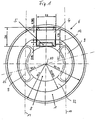
- the illustrated embodiment of an eye implant 6 is designed as an intraocular lens. This has one optical lens part 1, which in the visual area of the eye can be used.
- the optical lens part 8 has an optical one Axis 10, which is substantially perpendicular to the plane of the drawing 1 runs.
- the optical axis is implanted Condition essentially aligned with the visual axis of the eye.
- the optical lens part 8 essentially covers that Field of view of the eye.
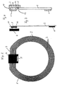
- a coil 1 which in the Transmitting and receiving device forms the inductance.
- the Coil is made of planar coil turns 3, in the form of side by side lying conductor tracks formed.
- the conductor tracks the coil turns 3 lie side by side in one essentially perpendicular to the optical axis 10 Level.
- the width of a coil turn is of the order of magnitude from about 3 to 90 ⁇ m, preferably from about 10 to 90 ⁇ m.
- There can be about 10 to 65 coil turns in each Level for the coil 1 may be provided.
- the coil turns 3 can, for example, by Galvanic deposition as used in microstructuring processes is known to be manufactured.
- the coil 1 an annular surface.
- the coil can also be oval, oval-like be trained or some other configuration to have.
- the carrier film 2 On the carrier film 2 is also the electronics of the telemetric system, which is in an electronic module (Chip) 4 is accommodated, of course several electronic modules can also be used.
- a sensor 5 for detecting those to be measured physical size, especially the intraocular pressure be provided.
- the electronic Module 4 contacted with the coil 1 in a suitable manner (electrical contacts 11).
- the electrical contact 11 between the Coil 1 and the electronic component 4 can be in hybrid or Flip chip technology can be achieved through bonding.
- the electrical contact points 11 ( Figure 3) can by Gold bumps with a thickness of 30 ⁇ m and less formed become.
- the chip or can the electronic components in one or more Films incorporated and thus foldable or rollable.
- the planar coil turns have a thickness (height) in the Range from 5 to 60 ⁇ m.
- the height of the electronic component 4 is approx. 600 ⁇ m and can be much smaller for example, be 300 microns.
- the area of the electronic Module 4 is approximately 2.0 mm x 2.0 mm.
- the thickness of the carrier film can be about 8 ⁇ m.
- the coil can have an outer radius 5.15 mm and an inner radius of 3.85 mm exhibit.
- the area of the carrier film 2 which is within the coil 1 lies, can be punched out, so that the carrier film 2 as an annular carrier film, which essentially is covered with the coil turns 3, is present.
- the carrier film 2 with the telemetric arranged thereon Devices as shown in Figures 2 and 3 is made of a biocompatible implant material, in particular Complete lens material, especially by pouring envelops.
- the implant material or lens material covers also the sensor 5, which in particular as a pressure sensor is trained.
- Figure 1 shows the intraocular lens, in which is the telemetric shown in Figures 2 to 4 System is poured. The given again in Figure 1 Dimensions are exemplary, which are within the limits permitted for an eye implantation can be varied are.
- the coil 1 is located within an annular haptic area, which the optical lens part 8 concentrically surrounds. It can be act a circular ring or oval or oval-like ring.
- One between this ring-shaped haptic area and the optical one Lens part 8 lying annular region 12 of the Lens material is provided with elongated holes 9 on their Boundary edges approximately concentric to the annular Coil 1 and the annular region 12 around the optical axis 10 extend.
- These slots 9 not only make it easier the folding or rolling of the lens, but support the Fixation of the lens in the eye, because eye tissue in these oblong holes can grow in.
- the sensor 5 is in the vicinity of the optical Lens part 8.
- the sensor 5 is from enclosed in a lens material that is between two Ends of the elongated holes 9 in the annular region 12 of the lens material located.
- the lens material is used for transmission the physical quantity to be measured in the eye, for example temperature or intraocular pressure.
- a polyorganosiloxane, especially polydimethylsiloxane comes for the lens material to use. It is also possible a different transmission medium in the area of the sensor 5 or one on the physical quantity (e.g. pressure, Temperature) appealing sensor area or to expose this area, as is still the case in FIG. 4 is explained.
- the outside diameter of the intraocular lens can be about 12 mm or less z. B. 8.5 mm.
- the diameter of the Optical lens part 8 can be 6 mm or less, for example 4.8 mm.
- the thickness of the lens at the center of the optical Lens part 8 can be about 0.780 mm or less. In the non-optical range, the thickness can be 0.500 mm or be less, but in the field of electronic Unit 4 ensures that this from the lens material is completely enveloped and accordingly the lens in it Area has a corresponding thickness.
- the length of the Elongated holes 9 can be dimensioned approximately 4.6 mm or less.
- the width can be 1.2 mm or less.
- coil 1 and electronic module 4 on the same side of the carrier film 2.
- Coil 1 on one side of the carrier film 2 and the electronic Module 4 on the other side of the carrier film 2.
- the electrical contact 11 between the coil 1 and the Electronic component 4 is made with the help of through-plating through the carrier film 2.
- the exemplary embodiment in FIG. 4 can be a more sensitive to the physical quantity to be recorded Area of the sensor 5 must be exposed.
- the exemplary embodiment is a sensor surface 13.
- a recess can be provided in the carrier film 2.
- This recess is also in the enveloping implant or intraocular lens material.
- the exposed sensor surface can also on the other hand, i.e. on the outside of the sensor 5 lie.
- the implant or Lens material around fold edges running approximately parallel to each other 14, folded or rolled on either side of the electronic module 4 lie. Even if the electronic Module 4 from a non-foldable monolithic There is a significant reduction of the implant cross section for the implantation.
- the two Folded edges 14 run on both sides of the electronic module.
- the implant can also pass through the fold edge 15 running the center of the lens (optical axis 10) be folded. From this it can be seen that it is a big one Number of folding options for the implant, even if the electronic module 4 is monolithic. Due to the special design of the coil 1, this is under Achieving a high inductivity foldable.
- a memory can be provided in the electronic module 4 be the sensor 5, in particular the pressure sensor 5 stores continuously recorded pressure values.
- This Pressure values can from this memory for example from time to time accessed every one week be and from the telemetry device to a no closer Receiving device shown with connected evaluation device be transmitted, such as in the German patent DE 197 28 069 C1 is described.
- the electronic component 4 is off foldable carrier material is formed, so that a deformation the intraocular lens to a small diameter is possible and only a small cut for the eye Implantation must be provided.
- the lens material is trained in such a way that after implantation unfolded and takes the desired lens shape.
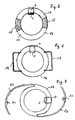
- an implant body 16 is formed in a ring shape.
- the recess provided in the interior of the ring is at least as follows dimensioned to be out of view if that annular implant is arranged in the eye.
- the coil shown is designed as shown in FIG. 2 is shown. It is on one or both Surfaces of the annular implant.
- the connection of the Sensor 5 and the electronic component 4 takes place in the same way as in the previous embodiments was explained.
- the sensor 5 is located within the annular arrangement of the coil 1, as shown in Figure 2 is seen.
- annular implant 16 made of hard or rigid ring parts 17, preferably made of PMMA and flexible ring parts 18, in particular made of silicone. This is the folding of the annular implant 16 by one through the flexible ring parts 18 fold axis possible.
- the outside diameter the ring is about 12 to 15 mm.
- the width of the ring can be 1 to 3 mm.
- the annular implant body 16 has closed Haptic loops 19.
- the embodiment shown in Figure 7 has open haptic loops 20.
- the ring-shaped See implant body 16 of exemplary embodiments 6 and 7 preferably made of silicone rubber.
- the haptic loops 19 and 20 are preferably made of a rigid material, in particular PMMA.
- fixation holes in the open haptic loops 21 provided. This will ensure stable positioning of the implant body 16 ensured in the eye.
- the Embodiments of Figures 5 to 7 are for fixation suitable in the sulcus of the eye. If necessary, too in the embodiment of Figure 5 additional no further Fixation holes shown may be provided.
- inventions of Figures 5, 6 and 7 can with an envelope made of silicone rubber or another biocompatible casing must be completely covered.
- the Transfer of intraocular pressure to the sensor surface of the Pressure sensor 5 takes place via this flexible envelope.
- the Wrapping material forms the transmission medium for intraocular pressure on the sensor surface of sensor 5.
Landscapes
- Health & Medical Sciences (AREA)
- Life Sciences & Earth Sciences (AREA)
- Engineering & Computer Science (AREA)
- Molecular Biology (AREA)
- Animal Behavior & Ethology (AREA)
- Biophysics (AREA)
- Veterinary Medicine (AREA)
- Biomedical Technology (AREA)
- Heart & Thoracic Surgery (AREA)
- Medical Informatics (AREA)
- Public Health (AREA)
- Surgery (AREA)
- Physics & Mathematics (AREA)
- General Health & Medical Sciences (AREA)
- Computer Networks & Wireless Communication (AREA)
- Pathology (AREA)
- Ophthalmology & Optometry (AREA)
- Prostheses (AREA)
- Eye Examination Apparatus (AREA)
- Measuring And Recording Apparatus For Diagnosis (AREA)
Description
- Figur 1
- eine Draufsicht auf ein als Intraokularlinse ausgebildetes Ausführungsbeispiel;
- Figur 2
- in Draufsicht eine Ausführungsform für ein telemetrisches System, welches bei dem in der Figur 1 dargestellten Ausführungsbeispiel zur Anwendung kommen kann;
- Figur 3
- eine schnittbildliche Darstellung des in Figur 2 dargestellten telemetrischen Systems;
- Figur 4
- eine schnittbildliche Darstellung eines telemetrischen Systems eines weiteren Ausführungsbeispiels;
- Figur 5
- ein Ausführungsbeispiel für eine ringförmiges Implantat;
- Figur 6
- ein weiteres Ausführungsbeispiel für ein ringförmiges Implantat mit geschlossenen Haptikschlaufen; und
- Figur 7
- ein Ausführungsbeispiel für ein ringförmiges Implantat mit offenen Haptikschlaufen.
- 1
- Spule
- 2
- Trägerfolie
- 3
- Spulenwindungen
- 4
- elektronischer Baustein (Chip)
- 5
- Sensor, insbesondere Drucksensor
- 6
- Implantat, insbesondere Intraokularlinse
- 7
- geradliniger Windungsbereich
- 8
- optischer Linsenteil
- 9
- Langloch
- 10
- optische Achse
- 11
- elektrische Kontaktierung
- 12
- ringförmiger Bereich
- 13
- Sensorfläche
- 14
- Faltkante
- 15
- Faltkante
- 16
- ringförmiger Implantatkörper
- 17
- starres Ringteil
- 18
- flexibles Ringteil
- 19
- geschlossene Haptikschlaufe
- 20
- offene Haptikschlaufe
- 21
- Fixationsloch
Claims (18)
- Vorrichtung zum Messen physikalischer Größen im Auge mit einem faltbaren Implantat, an welchem außerhalb eines das Blickfeld des Auges überdeckenden Implantatteil eine Fernmesseinrichtung mit einem Sensor und einer eine Spule aufweisenden Sendeeinrichtung zur drahtlosen Übertragung von den Sensorsignalen entsprechenden Informationen angeordnet ist, und einer außerhalb des Auges angeordneten Empfangseinrichtung, welche die von der Sendeeinrichtung gesendeten Informationen empfängt, und einer Auswerteeinrichtung, welche die empfangenen Informationen in wiedergebbare Daten wandelt, dadurch gekennzeichnet, dass auf einem faltbaren ringförmigen Träger (2; 16) die Spule (1) in Form mehrerer nebeneinander liegender Spulenwindungen in wenigstens einer Fläche angeordnet ist und mit der Spule wenigstens ein die Elektronik der Fernmesseinrichtung enthaltender elektronischer Baustein (4) elektrisch kontaktiert ist und dass diese Anordnung in das faltbare biokompatible Implantatmaterial eingegossen ist.
- Vorrichtung nach Anspruch 1, dadurch gekennzeichnet, dass Spulenwindungen (3) aus planaren elektrischen Leiterbahnen gebildet sind.
- Vorrichtung nach Anspruch 1 oder 2, dadurch gekennzeichnet, dass die Spulenwindungen (3) in einer oder mehreren Ebenen angeordnet sind.
- Vorrichtung nach einem der Ansprüche 1 bis 3, dadurch gekennzeichnet, dass der Sensor (5) ganz oder teilweise von einem die physikalische Größe übertragenden Übertragungsmedium umhüllt ist.
- Vorrichtung nach einem der Ansprüche 1 bis 4, dadurch gekennzeichnet, dass das biokompatible Material, mit welchem die Vorrichtung umhüllt ist, dass Übertragungsmedium bildet.
- Vorrichtung nach einem der Ansprüche 1 bis 5, dadurch gekennzeichnet, dass die Spulenwindungen (3) im Bereich ihrer Verbindung mit dem elektronischen Baustein (4) im wesentlichen geradlinig verlaufen.
- Vorrichtung nach einem der Ansprüche 1 bis 6, dadurch gekennzeichnet, dass die Spulenwindungen (3) im wesentlichen sich im gesamten außerhalb des Blickfeldes des Auges liegenden Implantatteil erstrecken.
- Vorrichtung nach einem der Ansprüche 1 bis 7, dadurch gekennzeichnet, dass der Sensor (5) als Drucksensor ausgebildet ist.
- Vorrichtung nach Anspruch 8, dadurch gekennzeichnet, dass der Drucksensor (5) kontinuierlich den Augeninnendruck mißt und die Elektronik der Fernmesseinrichtung einen Speicher aufweist, in welchem die Sensorsignale für ein zeitlich begrenztes Senden an eine Empfangseinrichtung gespeichert werden.
- Vorrichtung nach einem der Ansprüche 1 bis 9, dadurch gekennzeichnet, dass der Sensor (5) in einem die Fläche der Spulenwindungen (3) nicht überlappenden Bereich außerhalb des Blickfeldes des Auges liegt.
- Vorrichtung nach einem der Ansprüche 1 bis 10, dadurch gekennzeichnet, dass der Sensor (5) innerhalb des von der Spule (1) gebildeten Ringes liegt.
- Vorrichtung nach einem der Ansprüche 1 bis 11, dadurch gekennzeichnet, dass das Implantat (6) als Intraokularlinse ausgebildet ist und dass der ringförmige Träger (2) im Bereich des optischen Linsenteils (8) eine Ausnehmung aufweist, welche innerhalb der Spulenwindungen (3) liegt.
- Vorrichtung nach einem der Ansprüche 1 bis 12, dadurch gekennzeichnet, dass im Implantatmaterial zwischen der Spule (1) und dem das Blickfeld durchsetzenden Implantatteil, insbesondere optischen Linsenteil (8) der Intraokularlinse, Langlöchern (9) eingeformt sind.
- Vorrichtung nach Anspruch 13, dadurch gekennzeichnet, dass der Sensor (5) in einem ringförmigen Bereich (12) des Implantatmaterials liegt, in welchem die Langlöcher (9) sich erstrecken.
- Vorrichtung nach einem der Ansprüche 1 bis 14, dadurch gekennzeichnet, dass die Fläche bzw. die Flächen, in welcher bzw. in welchen die Spule (1) angeordnet ist, sich etwa senkrecht zur optischen Achse (10) des als Intraokularlinse ausgebildeten Implantats (6) erstreckt bzw. erstrecken.
- Vorrichtung nach einem der Ansprüche 1 bis 15, dadurch gekennzeichnet, dass die Spule (1) an der einen Oberfläche und der elektronische Baustein (4) auf der anderen Oberfläche des ringförmigen Trägers (2; 16) angeordnet sind.
- Vorrichtung nach einem der Ansprüche 1 bis 11 und 15, 16, gekennzeichnet durch einen ringförmigen Implantatkörper (16) aus zumindest teilweise flexiblen Material, welcher den Träger für die Spule (1) bildet.
- Vorrichtung nach Anspruch 17, dadurch gekennzeichnet, dass der ringförmige Implantatkörper (16) im Sulcus des Auges fixierbar ist.
Applications Claiming Priority (3)
| Application Number | Priority Date | Filing Date | Title |
|---|---|---|---|
| DE19945879A DE19945879C2 (de) | 1999-09-24 | 1999-09-24 | Vorrichtung zum Messen des Augeninnendruckes mit einem faltbaren Implantat |
| DE19945879 | 1999-09-24 | ||
| PCT/EP2000/009301 WO2001021063A1 (de) | 1999-09-24 | 2000-09-22 | Vorrichtung zum messen von physikalischen grössen, insbesondere zur druckmessung im auge |
Publications (2)
| Publication Number | Publication Date |
|---|---|
| EP1213991A1 EP1213991A1 (de) | 2002-06-19 |
| EP1213991B1 true EP1213991B1 (de) | 2003-06-04 |
Family
ID=7923221
Family Applications (1)
| Application Number | Title | Priority Date | Filing Date |
|---|---|---|---|
| EP00964227A Expired - Lifetime EP1213991B1 (de) | 1999-09-24 | 2000-09-22 | Vorrichtung zum messen von physikalischen grössen, insbesondere zur druckmessung im auge |
Country Status (7)
| Country | Link |
|---|---|
| US (1) | US6796942B1 (de) |
| EP (1) | EP1213991B1 (de) |
| JP (1) | JP4251387B2 (de) |
| AT (1) | ATE241932T1 (de) |
| DE (2) | DE19945879C2 (de) |
| ES (1) | ES2200938T3 (de) |
| WO (1) | WO2001021063A1 (de) |
Cited By (24)
| Publication number | Priority date | Publication date | Assignee | Title |
|---|---|---|---|---|
| US7658196B2 (en) | 2005-02-24 | 2010-02-09 | Ethicon Endo-Surgery, Inc. | System and method for determining implanted device orientation |
| US7775215B2 (en) | 2005-02-24 | 2010-08-17 | Ethicon Endo-Surgery, Inc. | System and method for determining implanted device positioning and obtaining pressure data |
| US7775966B2 (en) | 2005-02-24 | 2010-08-17 | Ethicon Endo-Surgery, Inc. | Non-invasive pressure measurement in a fluid adjustable restrictive device |
| US7844342B2 (en) | 2008-02-07 | 2010-11-30 | Ethicon Endo-Surgery, Inc. | Powering implantable restriction systems using light |
| US7927270B2 (en) | 2005-02-24 | 2011-04-19 | Ethicon Endo-Surgery, Inc. | External mechanical pressure sensor for gastric band pressure measurements |
| US8016744B2 (en) | 2005-02-24 | 2011-09-13 | Ethicon Endo-Surgery, Inc. | External pressure-based gastric band adjustment system and method |
| US8016745B2 (en) | 2005-02-24 | 2011-09-13 | Ethicon Endo-Surgery, Inc. | Monitoring of a food intake restriction device |
| US8034065B2 (en) | 2008-02-26 | 2011-10-11 | Ethicon Endo-Surgery, Inc. | Controlling pressure in adjustable restriction devices |
| US8057492B2 (en) | 2008-02-12 | 2011-11-15 | Ethicon Endo-Surgery, Inc. | Automatically adjusting band system with MEMS pump |
| US8066629B2 (en) | 2005-02-24 | 2011-11-29 | Ethicon Endo-Surgery, Inc. | Apparatus for adjustment and sensing of gastric band pressure |
| US8100870B2 (en) | 2007-12-14 | 2012-01-24 | Ethicon Endo-Surgery, Inc. | Adjustable height gastric restriction devices and methods |
| US8114345B2 (en) | 2008-02-08 | 2012-02-14 | Ethicon Endo-Surgery, Inc. | System and method of sterilizing an implantable medical device |
| US8142452B2 (en) | 2007-12-27 | 2012-03-27 | Ethicon Endo-Surgery, Inc. | Controlling pressure in adjustable restriction devices |
| US8152710B2 (en) | 2006-04-06 | 2012-04-10 | Ethicon Endo-Surgery, Inc. | Physiological parameter analysis for an implantable restriction device and a data logger |
| US8187163B2 (en) | 2007-12-10 | 2012-05-29 | Ethicon Endo-Surgery, Inc. | Methods for implanting a gastric restriction device |
| US8187162B2 (en) | 2008-03-06 | 2012-05-29 | Ethicon Endo-Surgery, Inc. | Reorientation port |
| US8192350B2 (en) | 2008-01-28 | 2012-06-05 | Ethicon Endo-Surgery, Inc. | Methods and devices for measuring impedance in a gastric restriction system |
| US8221439B2 (en) | 2008-02-07 | 2012-07-17 | Ethicon Endo-Surgery, Inc. | Powering implantable restriction systems using kinetic motion |
| US8233995B2 (en) | 2008-03-06 | 2012-07-31 | Ethicon Endo-Surgery, Inc. | System and method of aligning an implantable antenna |
| US8337389B2 (en) | 2008-01-28 | 2012-12-25 | Ethicon Endo-Surgery, Inc. | Methods and devices for diagnosing performance of a gastric restriction system |
| US8377079B2 (en) | 2007-12-27 | 2013-02-19 | Ethicon Endo-Surgery, Inc. | Constant force mechanisms for regulating restriction devices |
| US8591532B2 (en) | 2008-02-12 | 2013-11-26 | Ethicon Endo-Sugery, Inc. | Automatically adjusting band system |
| US8591395B2 (en) | 2008-01-28 | 2013-11-26 | Ethicon Endo-Surgery, Inc. | Gastric restriction device data handling devices and methods |
| US8870742B2 (en) | 2006-04-06 | 2014-10-28 | Ethicon Endo-Surgery, Inc. | GUI for an implantable restriction device and a data logger |
Families Citing this family (45)
| Publication number | Priority date | Publication date | Assignee | Title |
|---|---|---|---|---|
| US7488303B1 (en) * | 2002-09-21 | 2009-02-10 | Glaukos Corporation | Ocular implant with anchor and multiple openings |
| GB2374925A (en) * | 2001-04-24 | 2002-10-30 | Anant Sharma | Pressure detectors |
| US7678065B2 (en) | 2001-05-02 | 2010-03-16 | Glaukos Corporation | Implant with intraocular pressure sensor for glaucoma treatment |
| US7094225B2 (en) | 2001-05-03 | 2006-08-22 | Glaukos Corporation | Medical device and methods of use of glaucoma treatment |
| EP1401327B1 (de) * | 2001-06-29 | 2006-03-08 | Ecole Polytechnique Fédérale de Lausanne (EPFL) | Vorrichtung zur messung des intraokularen druckes |
| DE10156469B4 (de) * | 2001-11-16 | 2004-05-13 | Cranium Telemetrics Gmbh | Vorrichtung zur intrakorporalen Messung des Hirndruckes |
| DE10156494B4 (de) * | 2001-11-16 | 2006-02-09 | Campus Micro Technologies Gmbh | Implantat zum Einbau in den menschlichen oder tierischen Körper |
| US7951155B2 (en) | 2002-03-15 | 2011-05-31 | Glaukos Corporation | Combined treatment for cataract and glaucoma treatment |
| WO2004062480A2 (en) * | 2003-01-09 | 2004-07-29 | The Regents Of The University Of California | Implantable devices and methods for measuring intraocular, subconjunctival or subdermal pressure and/or analyte concentration |
| US7557433B2 (en) | 2004-10-25 | 2009-07-07 | Mccain Joseph H | Microelectronic device with integrated energy source |
| DE10353144A1 (de) * | 2003-11-14 | 2005-06-02 | Cranium Telemetrics Gmbh | Implantat zur Durchführung intrakorpolarer Messungen |
| US20070106200A1 (en) * | 2005-11-08 | 2007-05-10 | Brian Levy | Intraocular shunt device and method |
| US7682313B2 (en) | 2005-11-23 | 2010-03-23 | Vital Sensors Holding Company, Inc. | Implantable pressure monitor |
| US7686768B2 (en) | 2005-11-23 | 2010-03-30 | Vital Sensors Holding Company, Inc. | Implantable pressure monitor |
| DE112007002378T5 (de) | 2006-10-24 | 2009-09-03 | Bradley Fixtures Corp., Menomonee Falls | Kapazitive Messung für Waschraum-Armaturen |
| US7842004B2 (en) * | 2007-10-31 | 2010-11-30 | Codman & Shurtleff, Inc. | Wireless pressure setting indicator |
| US9204812B2 (en) * | 2007-10-31 | 2015-12-08 | DePuy Synthes Products, LLC | Wireless pressure sensing shunts |
| US8454524B2 (en) | 2007-10-31 | 2013-06-04 | DePuy Synthes Products, LLC | Wireless flow sensor |
| US8480612B2 (en) | 2007-10-31 | 2013-07-09 | DePuy Synthes Products, LLC | Wireless shunts with storage |
| US20110137391A1 (en) * | 2008-06-03 | 2011-06-09 | Leigh C Roger | Foldable coil for an implantable medical device |
| DE102008040142A1 (de) * | 2008-07-03 | 2010-01-07 | Robert Bosch Gmbh | Kapselspannring mit Spule für die induktive Kopplung an ein externes elektromagnetisches Feld |
| US20100016704A1 (en) * | 2008-07-16 | 2010-01-21 | Naber John F | Method and system for monitoring a condition of an eye |
| MX2012000657A (es) * | 2009-07-14 | 2012-03-29 | Elenza Inc | Diseños de pliegue para lentes intraoculares. |
| EP2477534A1 (de) | 2009-09-18 | 2012-07-25 | Orthomems, Inc. | Implantierbare mems-sensor-vorrichtungen für den augeninnendruck und verfahren zur glaukomüberwachung |
| BR112012016419B1 (pt) * | 2010-01-05 | 2020-12-29 | Sensimed Sa | dispositivo de monitoramento da pressão intraocular, kit e sistema de monitoramento da pressão intraocular |
| DE102010031432A1 (de) | 2010-07-16 | 2012-01-19 | Robert Bosch Gmbh | Augeninnendrucksensor |
| US20120238857A1 (en) * | 2010-09-16 | 2012-09-20 | Orthomems, Inc. | Expandable implantable pressure sensor for intraocular surgery |
| US8915877B2 (en) | 2010-10-12 | 2014-12-23 | Emmett T. Cunningham, JR. | Glaucoma drainage device and uses thereof |
| US9370444B2 (en) | 2010-10-12 | 2016-06-21 | Emmett T. Cunningham, JR. | Subconjunctival conformer device and uses thereof |
| WO2012137067A2 (en) | 2011-04-07 | 2012-10-11 | Oculox Technology | Intraocular pressure monitoring device and methods |
| ES2666857T3 (es) | 2011-07-18 | 2018-05-08 | Mor-Research Applications Ltd. | Un dispositivo para ajustar la presión intraocular |
| EP2755549A1 (de) | 2011-09-13 | 2014-07-23 | Dose Medical Corporation | Intraokularer physiologischer sensor |
| DE102012200574A1 (de) | 2012-01-17 | 2013-07-18 | Robert Bosch Gmbh | Implantatvorrichtung, Sensormodul, Einweginjektor mit einer Implantatvorrichtung und Verfahren zum Herstellen einer Implantatvorrichtung |
| US9072465B2 (en) | 2012-04-03 | 2015-07-07 | Johnson & Johnson Vision Care, Inc. | Blink detection system for electronic ophthalmic lens |
| US8834566B1 (en) | 2012-09-12 | 2014-09-16 | David Jones | Presbyopia-correcting intraocular lens implant |
| US20140107459A1 (en) * | 2012-10-11 | 2014-04-17 | Alcon Research, Ltd. | Devices, systems, and methods for intraocular measurements |
| US9730638B2 (en) | 2013-03-13 | 2017-08-15 | Glaukos Corporation | Intraocular physiological sensor |
| EP2979662A1 (de) * | 2014-08-01 | 2016-02-03 | Akkolens International B.V. | Intraokularlinse mit einem stromgenerator und zusätzlichen funktionssystemen |
| WO2017210316A1 (en) | 2016-05-31 | 2017-12-07 | Qura, Inc. | Implantable intraocular pressure sensors and methods of use |
| DE102016221371A1 (de) | 2016-10-28 | 2018-05-03 | Implandata Ophthalmic Products Gmbh | Ringimplantat |
| DE102017107576A1 (de) | 2017-04-07 | 2018-10-11 | Implandata Ophthalmic Products Gmbh | Flachbaugruppe zur Bestimmung des Augeninnendrucks zur Implantation in den menschlichen Körper |
| US11602427B2 (en) * | 2018-03-30 | 2023-03-14 | Qura, Inc. | Intraocular lenses including an intraocular pressure sensor |
| WO2019214823A1 (de) * | 2018-05-09 | 2019-11-14 | Implandata Ophthalmic Products Gmbh | Flachbaugruppe zur bestimmung des augeninnendrucks zur implantation in den menschlichen körper |
| WO2020236139A1 (en) * | 2019-05-17 | 2020-11-26 | Qura, Inc. | Intraocular lenses with intraocular pressure sensors and methods of manufacture |
| JP7535122B2 (ja) * | 2020-03-23 | 2024-08-15 | テクタス コーポレイション | 電子眼内デバイス |
Family Cites Families (5)
| Publication number | Priority date | Publication date | Assignee | Title |
|---|---|---|---|---|
| US4816031A (en) * | 1988-01-29 | 1989-03-28 | Pfoff David S | Intraocular lens system |
| US5005577A (en) * | 1988-08-23 | 1991-04-09 | Frenkel Ronald E P | Intraocular lens pressure monitoring device |
| DE19728069C1 (de) * | 1997-07-01 | 1999-02-11 | Acritec Gmbh | Vorrichtung zur Messung des Augeninnendrucks |
| DE19744079A1 (de) * | 1997-10-06 | 1999-04-08 | Woehlk Contact Linsen Gmbh | Ophthalmische Linse |
| DE19858172A1 (de) * | 1998-12-16 | 2000-06-21 | Campus Micro Technologies Gmbh | Implantat zur Messung des Augeninnendrucks |
-
1999
- 1999-09-24 DE DE19945879A patent/DE19945879C2/de not_active Expired - Fee Related
-
2000
- 2000-09-22 AT AT00964227T patent/ATE241932T1/de active
- 2000-09-22 JP JP2001524497A patent/JP4251387B2/ja not_active Expired - Fee Related
- 2000-09-22 WO PCT/EP2000/009301 patent/WO2001021063A1/de active IP Right Grant
- 2000-09-22 US US10/089,363 patent/US6796942B1/en not_active Expired - Fee Related
- 2000-09-22 EP EP00964227A patent/EP1213991B1/de not_active Expired - Lifetime
- 2000-09-22 DE DE50002477T patent/DE50002477D1/de not_active Expired - Lifetime
- 2000-09-22 ES ES00964227T patent/ES2200938T3/es not_active Expired - Lifetime
Cited By (24)
| Publication number | Priority date | Publication date | Assignee | Title |
|---|---|---|---|---|
| US7658196B2 (en) | 2005-02-24 | 2010-02-09 | Ethicon Endo-Surgery, Inc. | System and method for determining implanted device orientation |
| US7775215B2 (en) | 2005-02-24 | 2010-08-17 | Ethicon Endo-Surgery, Inc. | System and method for determining implanted device positioning and obtaining pressure data |
| US7775966B2 (en) | 2005-02-24 | 2010-08-17 | Ethicon Endo-Surgery, Inc. | Non-invasive pressure measurement in a fluid adjustable restrictive device |
| US7927270B2 (en) | 2005-02-24 | 2011-04-19 | Ethicon Endo-Surgery, Inc. | External mechanical pressure sensor for gastric band pressure measurements |
| US8016744B2 (en) | 2005-02-24 | 2011-09-13 | Ethicon Endo-Surgery, Inc. | External pressure-based gastric band adjustment system and method |
| US8016745B2 (en) | 2005-02-24 | 2011-09-13 | Ethicon Endo-Surgery, Inc. | Monitoring of a food intake restriction device |
| US8066629B2 (en) | 2005-02-24 | 2011-11-29 | Ethicon Endo-Surgery, Inc. | Apparatus for adjustment and sensing of gastric band pressure |
| US8870742B2 (en) | 2006-04-06 | 2014-10-28 | Ethicon Endo-Surgery, Inc. | GUI for an implantable restriction device and a data logger |
| US8152710B2 (en) | 2006-04-06 | 2012-04-10 | Ethicon Endo-Surgery, Inc. | Physiological parameter analysis for an implantable restriction device and a data logger |
| US8187163B2 (en) | 2007-12-10 | 2012-05-29 | Ethicon Endo-Surgery, Inc. | Methods for implanting a gastric restriction device |
| US8100870B2 (en) | 2007-12-14 | 2012-01-24 | Ethicon Endo-Surgery, Inc. | Adjustable height gastric restriction devices and methods |
| US8142452B2 (en) | 2007-12-27 | 2012-03-27 | Ethicon Endo-Surgery, Inc. | Controlling pressure in adjustable restriction devices |
| US8377079B2 (en) | 2007-12-27 | 2013-02-19 | Ethicon Endo-Surgery, Inc. | Constant force mechanisms for regulating restriction devices |
| US8192350B2 (en) | 2008-01-28 | 2012-06-05 | Ethicon Endo-Surgery, Inc. | Methods and devices for measuring impedance in a gastric restriction system |
| US8337389B2 (en) | 2008-01-28 | 2012-12-25 | Ethicon Endo-Surgery, Inc. | Methods and devices for diagnosing performance of a gastric restriction system |
| US8591395B2 (en) | 2008-01-28 | 2013-11-26 | Ethicon Endo-Surgery, Inc. | Gastric restriction device data handling devices and methods |
| US8221439B2 (en) | 2008-02-07 | 2012-07-17 | Ethicon Endo-Surgery, Inc. | Powering implantable restriction systems using kinetic motion |
| US7844342B2 (en) | 2008-02-07 | 2010-11-30 | Ethicon Endo-Surgery, Inc. | Powering implantable restriction systems using light |
| US8114345B2 (en) | 2008-02-08 | 2012-02-14 | Ethicon Endo-Surgery, Inc. | System and method of sterilizing an implantable medical device |
| US8057492B2 (en) | 2008-02-12 | 2011-11-15 | Ethicon Endo-Surgery, Inc. | Automatically adjusting band system with MEMS pump |
| US8591532B2 (en) | 2008-02-12 | 2013-11-26 | Ethicon Endo-Sugery, Inc. | Automatically adjusting band system |
| US8034065B2 (en) | 2008-02-26 | 2011-10-11 | Ethicon Endo-Surgery, Inc. | Controlling pressure in adjustable restriction devices |
| US8187162B2 (en) | 2008-03-06 | 2012-05-29 | Ethicon Endo-Surgery, Inc. | Reorientation port |
| US8233995B2 (en) | 2008-03-06 | 2012-07-31 | Ethicon Endo-Surgery, Inc. | System and method of aligning an implantable antenna |
Also Published As
| Publication number | Publication date |
|---|---|
| DE50002477D1 (de) | 2003-07-10 |
| JP4251387B2 (ja) | 2009-04-08 |
| US6796942B1 (en) | 2004-09-28 |
| JP2003518962A (ja) | 2003-06-17 |
| EP1213991A1 (de) | 2002-06-19 |
| DE19945879A1 (de) | 2001-05-10 |
| ES2200938T3 (es) | 2004-03-16 |
| ATE241932T1 (de) | 2003-06-15 |
| DE19945879C2 (de) | 2002-01-03 |
| WO2001021063A1 (de) | 2001-03-29 |
Similar Documents
| Publication | Publication Date | Title |
|---|---|---|
| EP1213991B1 (de) | Vorrichtung zum messen von physikalischen grössen, insbesondere zur druckmessung im auge | |
| DE19640304C2 (de) | Chipmodul insbesondere zur Implantation in einen Chipkartenkörper | |
| DE19858172A1 (de) | Implantat zur Messung des Augeninnendrucks | |
| DE10156469B4 (de) | Vorrichtung zur intrakorporalen Messung des Hirndruckes | |
| DE69924290T2 (de) | Verfahren und sensoren zur drahtlosen messung physiologischer variablen | |
| DE68909894T3 (de) | Druckmessfühler mit flexibler gedruckter Schaltung. | |
| DE19728069C1 (de) | Vorrichtung zur Messung des Augeninnendrucks | |
| DE10128406B4 (de) | Antenne mit einem ferromagnetischen Kern und Verfahren zu ihrer Herstellung | |
| DE4104358C2 (de) | ||
| DE19825761C2 (de) | Vorrichtung zum Erfassen einer Dehnung und/oder einer Stauchung eines Körpers | |
| EP0325805A2 (de) | Messwertaufnehmer zur nichtinvasiven Messung von Schall, Druck und Vibrationen am menschlichen Körper | |
| DE10200617A1 (de) | Implantat zur Bestimmung des Augeninnendrucks | |
| EP2627247A1 (de) | Sensorsystem zum implantieren in einen körper und herstellungsverfahren des sensorsystems | |
| EP1664704A1 (de) | Kraftmesswandler | |
| DE19700393C2 (de) | Gehäuse mit einer Halbleiter-Sensoranordnung und Verfahren zu deren Herstellung | |
| DE10326389B4 (de) | Drucksensorvorrichtung mit Stiften, die mit einer Dehnungsmessanordnung ausgestattet sind | |
| DE10156494B4 (de) | Implantat zum Einbau in den menschlichen oder tierischen Körper | |
| DE10353144A1 (de) | Implantat zur Durchführung intrakorpolarer Messungen | |
| DE102004055220B4 (de) | Vorrichtung zur Intraokulardruckmessung | |
| DE19728512A1 (de) | Transponderanordnung und Verfahren zu deren Herstellung | |
| DE102004056756B4 (de) | Vorrichtung zur Intraokulardruckmessung | |
| DE102004061543B4 (de) | Implantat zur intraokularen Druckmessung | |
| DE102020213718A1 (de) | Medizinisches Implantat | |
| DE19733592A1 (de) | Vorrichtung zum Messen der Tomeszenz und Rigidität | |
| DE102011119358A1 (de) | Anordnung zur Erfassung von physiologischen Vitalparametern in Versuchstieren und anderen Lebewesen mit Hilfe der RFID Übertragungstechnik |
Legal Events
| Date | Code | Title | Description |
|---|---|---|---|
| PUAI | Public reference made under article 153(3) epc to a published international application that has entered the european phase |
Free format text: ORIGINAL CODE: 0009012 |
|
| 17P | Request for examination filed |
Effective date: 20020311 |
|
| AK | Designated contracting states |
Kind code of ref document: A1 Designated state(s): AT BE CH CY DE DK ES FI FR GB GR IE IT LI LU MC NL PT SE |
|
| GRAH | Despatch of communication of intention to grant a patent |
Free format text: ORIGINAL CODE: EPIDOS IGRA |
|
| GRAH | Despatch of communication of intention to grant a patent |
Free format text: ORIGINAL CODE: EPIDOS IGRA |
|
| GRAA | (expected) grant |
Free format text: ORIGINAL CODE: 0009210 |
|
| AK | Designated contracting states |
Designated state(s): AT BE CH CY DE DK ES FI FR GB GR IE IT LI LU MC NL PT SE |
|
| PG25 | Lapsed in a contracting state [announced via postgrant information from national office to epo] |
Ref country code: FI Free format text: LAPSE BECAUSE OF FAILURE TO SUBMIT A TRANSLATION OF THE DESCRIPTION OR TO PAY THE FEE WITHIN THE PRESCRIBED TIME-LIMIT Effective date: 20030604 Ref country code: IE Free format text: LAPSE BECAUSE OF FAILURE TO SUBMIT A TRANSLATION OF THE DESCRIPTION OR TO PAY THE FEE WITHIN THE PRESCRIBED TIME-LIMIT Effective date: 20030604 |
|
| REG | Reference to a national code |
Ref country code: GB Ref legal event code: FG4D Free format text: NOT ENGLISH |
|
| REG | Reference to a national code |
Ref country code: CH Ref legal event code: EP |
|
| REG | Reference to a national code |
Ref country code: CH Ref legal event code: NV Representative=s name: BOVARD AG PATENTANWAELTE |
|
| REG | Reference to a national code |
Ref country code: IE Ref legal event code: FG4D Free format text: GERMAN |
|
| REF | Corresponds to: |
Ref document number: 50002477 Country of ref document: DE Date of ref document: 20030710 Kind code of ref document: P |
|
| PG25 | Lapsed in a contracting state [announced via postgrant information from national office to epo] |
Ref country code: PT Free format text: LAPSE BECAUSE OF FAILURE TO SUBMIT A TRANSLATION OF THE DESCRIPTION OR TO PAY THE FEE WITHIN THE PRESCRIBED TIME-LIMIT Effective date: 20030904 Ref country code: DK Free format text: LAPSE BECAUSE OF FAILURE TO SUBMIT A TRANSLATION OF THE DESCRIPTION OR TO PAY THE FEE WITHIN THE PRESCRIBED TIME-LIMIT Effective date: 20030904 Ref country code: GR Free format text: LAPSE BECAUSE OF FAILURE TO SUBMIT A TRANSLATION OF THE DESCRIPTION OR TO PAY THE FEE WITHIN THE PRESCRIBED TIME-LIMIT Effective date: 20030904 |
|
| REG | Reference to a national code |
Ref country code: SE Ref legal event code: TRGR |
|
| PG25 | Lapsed in a contracting state [announced via postgrant information from national office to epo] |
Ref country code: CY Free format text: LAPSE BECAUSE OF FAILURE TO SUBMIT A TRANSLATION OF THE DESCRIPTION OR TO PAY THE FEE WITHIN THE PRESCRIBED TIME-LIMIT Effective date: 20030922 |
|
| GBT | Gb: translation of ep patent filed (gb section 77(6)(a)/1977) | ||
| PG25 | Lapsed in a contracting state [announced via postgrant information from national office to epo] |
Ref country code: MC Free format text: LAPSE BECAUSE OF NON-PAYMENT OF DUE FEES Effective date: 20030930 |
|
| REG | Reference to a national code |
Ref country code: IE Ref legal event code: FD4D |
|
| REG | Reference to a national code |
Ref country code: ES Ref legal event code: FG2A Ref document number: 2200938 Country of ref document: ES Kind code of ref document: T3 |
|
| ET | Fr: translation filed | ||
| PLBE | No opposition filed within time limit |
Free format text: ORIGINAL CODE: 0009261 |
|
| STAA | Information on the status of an ep patent application or granted ep patent |
Free format text: STATUS: NO OPPOSITION FILED WITHIN TIME LIMIT |
|
| 26N | No opposition filed |
Effective date: 20040305 |
|
| REG | Reference to a national code |
Ref country code: CH Ref legal event code: PFA Owner name: MESOTEC GESELLSCHAFT FUER MEDIZINISCHE SENSORTECH Free format text: MESOTEC GESELLSCHAFT FUER MEDIZINISCHE SENSORTECHNIK MBH#VAHRENWALDER STRASSE 7#30165 HANNOVER (DE) $ ACRITEC GESELLSCHAFT FUER OPHTHALMOLOGISCHE PRODUKTE MBH#LINDENSTRASSE 24#16548 GLIENICKE (DE) -TRANSFER TO- MESOTEC GESELLSCHAFT FUER MEDIZINISCHE SENSORTECHNIK MBH#VAHRENWALDER STRASSE 7#30165 HANNOVER (DE) $ *ACRI.TEC GESELLSCHAFT FUER OPHTHALMOLOGISCHE PRODUKTE MBH#NEUENDORFSTRASSE 20A#16761 HENNIGSDORF (DE) |
|
| REG | Reference to a national code |
Ref country code: FR Ref legal event code: CA Ref country code: FR Ref legal event code: CD |
|
| REG | Reference to a national code |
Ref country code: ES Ref legal event code: PC2A |
|
| NLT1 | Nl: modifications of names registered in virtue of documents presented to the patent office pursuant to art. 16 a, paragraph 1 |
Owner name: MESOTEC GESELLSCHAFT FUER MEDIZINISCHE SENSORTECHN Owner name: *ACRI.TEC AG GESELLSCHAFT FUER OPHTHALMOLOGISCHE P |
|
| REG | Reference to a national code |
Ref country code: GB Ref legal event code: 732E |
|
| REG | Reference to a national code |
Ref country code: FR Ref legal event code: TQ |
|
| NLS | Nl: assignments of ep-patents |
Owner name: *ACRI.TEC AG GESELLSCHAFT FUER OPHTHALMOLOGISCHE P Effective date: 20070313 Owner name: MEDICAL SENSOR TECHNOLOGIES, INC. Effective date: 20070313 |
|
| REG | Reference to a national code |
Ref country code: FR Ref legal event code: CD Ref country code: FR Ref legal event code: CJ |
|
| BECH | Be: change of holder |
Owner name: MEDICAL SENSOR TECHNOLOGIES INC. Effective date: 20070918 Owner name: *ACRITEC A.G.GESELLSCHAFT FUR OPHTHALMOLOGISCHE PR Effective date: 20070918 |
|
| REG | Reference to a national code |
Ref country code: ES Ref legal event code: PC2A |
|
| NLT1 | Nl: modifications of names registered in virtue of documents presented to the patent office pursuant to art. 16 a, paragraph 1 |
Owner name: * ACRI. TEC GMBH Owner name: MEDICAL SENSOR TECHNOLOGIES, INC. |
|
| REG | Reference to a national code |
Ref country code: CH Ref legal event code: PFA Owner name: MEDICAL SENSOR TECHNOLOGIES, INC. Free format text: *ACRI.TEC AG GESELLSCHAFT FUER OPHTHALMOLOGISCHE PRODUKTE#NEUENDORFSTRASSE 20 A#16761 HENNIGSDORF (DE) $ MEDICAL SENSOR TECHNOLOGIES, INC.#11 STANWIX STREET, 15TH FLOOR#PITTSBURGH, PA 15222-1319 (US) -TRANSFER TO- MEDICAL SENSOR TECHNOLOGIES, INC.#11 STANWIX STREET, 15TH FLOOR#PITTSBURGH, PA 15222-1319 (US) $ *ACRI.TEC GMBH#NEUENDORFSTRASSE 20A#16761 HENNIGSDORF (DE) |
|
| REG | Reference to a national code |
Ref country code: FR Ref legal event code: CD Ref country code: FR Ref legal event code: CJ |
|
| REG | Reference to a national code |
Ref country code: CH Ref legal event code: PFA Owner name: MEDICAL SENSOR TECHNOLOGIES, INC. Free format text: MEDICAL SENSOR TECHNOLOGIES, INC.#11 STANWIX STREET, 15TH FLOOR#PITTSBURGH, PA 15222-1319 (US) $ *ACRI.TEC GMBH#NEUENDORFSTRASSE 20A#16761 HENNIGSDORF (DE) -TRANSFER TO- MEDICAL SENSOR TECHNOLOGIES, INC.#11 STANWIX STREET, 15TH FLOOR#PITTSBURGH, PA 15222-1319 (US) $ *ACRI.TEC GMBH#NEUENDORFSTRASSE 20A#16761 HENNIGSDORF (DE) |
|
| REG | Reference to a national code |
Ref country code: FR Ref legal event code: PLFP Year of fee payment: 16 |
|
| PGFP | Annual fee paid to national office [announced via postgrant information from national office to epo] |
Ref country code: ES Payment date: 20150923 Year of fee payment: 16 Ref country code: LU Payment date: 20150922 Year of fee payment: 16 Ref country code: GB Payment date: 20150922 Year of fee payment: 16 |
|
| PGFP | Annual fee paid to national office [announced via postgrant information from national office to epo] |
Ref country code: SE Payment date: 20150922 Year of fee payment: 16 Ref country code: AT Payment date: 20150921 Year of fee payment: 16 Ref country code: BE Payment date: 20150921 Year of fee payment: 16 Ref country code: FR Payment date: 20150923 Year of fee payment: 16 |
|
| PGFP | Annual fee paid to national office [announced via postgrant information from national office to epo] |
Ref country code: CH Payment date: 20151109 Year of fee payment: 16 Ref country code: DE Payment date: 20151123 Year of fee payment: 16 Ref country code: IT Payment date: 20150925 Year of fee payment: 16 |
|
| PGFP | Annual fee paid to national office [announced via postgrant information from national office to epo] |
Ref country code: NL Payment date: 20150923 Year of fee payment: 16 |
|
| PG25 | Lapsed in a contracting state [announced via postgrant information from national office to epo] |
Ref country code: BE Free format text: LAPSE BECAUSE OF NON-PAYMENT OF DUE FEES Effective date: 20160930 |
|
| REG | Reference to a national code |
Ref country code: DE Ref legal event code: R119 Ref document number: 50002477 Country of ref document: DE |
|
| PG25 | Lapsed in a contracting state [announced via postgrant information from national office to epo] |
Ref country code: SE Free format text: LAPSE BECAUSE OF NON-PAYMENT OF DUE FEES Effective date: 20160923 |
|
| REG | Reference to a national code |
Ref country code: CH Ref legal event code: PL |
|
| REG | Reference to a national code |
Ref country code: SE Ref legal event code: EUG |
|
| REG | Reference to a national code |
Ref country code: NL Ref legal event code: MM Effective date: 20161001 |
|
| REG | Reference to a national code |
Ref country code: AT Ref legal event code: MM01 Ref document number: 241932 Country of ref document: AT Kind code of ref document: T Effective date: 20160922 |
|
| GBPC | Gb: european patent ceased through non-payment of renewal fee |
Effective date: 20160922 |
|
| PG25 | Lapsed in a contracting state [announced via postgrant information from national office to epo] |
Ref country code: NL Free format text: LAPSE BECAUSE OF NON-PAYMENT OF DUE FEES Effective date: 20161001 |
|
| REG | Reference to a national code |
Ref country code: FR Ref legal event code: ST Effective date: 20170531 |
|
| PG25 | Lapsed in a contracting state [announced via postgrant information from national office to epo] |
Ref country code: DE Free format text: LAPSE BECAUSE OF NON-PAYMENT OF DUE FEES Effective date: 20170401 Ref country code: GB Free format text: LAPSE BECAUSE OF NON-PAYMENT OF DUE FEES Effective date: 20160922 Ref country code: FR Free format text: LAPSE BECAUSE OF NON-PAYMENT OF DUE FEES Effective date: 20160930 Ref country code: CH Free format text: LAPSE BECAUSE OF NON-PAYMENT OF DUE FEES Effective date: 20160930 Ref country code: LI Free format text: LAPSE BECAUSE OF NON-PAYMENT OF DUE FEES Effective date: 20160930 |
|
| PG25 | Lapsed in a contracting state [announced via postgrant information from national office to epo] |
Ref country code: LU Free format text: LAPSE BECAUSE OF NON-PAYMENT OF DUE FEES Effective date: 20160922 Ref country code: IT Free format text: LAPSE BECAUSE OF NON-PAYMENT OF DUE FEES Effective date: 20160922 Ref country code: AT Free format text: LAPSE BECAUSE OF NON-PAYMENT OF DUE FEES Effective date: 20160922 |
|
| REG | Reference to a national code |
Ref country code: BE Ref legal event code: MM Effective date: 20160930 |
|
| PG25 | Lapsed in a contracting state [announced via postgrant information from national office to epo] |
Ref country code: ES Free format text: LAPSE BECAUSE OF NON-PAYMENT OF DUE FEES Effective date: 20160923 |
|
| REG | Reference to a national code |
Ref country code: ES Ref legal event code: FD2A Effective date: 20181120 |