EP1213528B1 - Balancesystem für handgeführte Kameras - Google Patents
Balancesystem für handgeführte Kameras Download PDFInfo
- Publication number
- EP1213528B1 EP1213528B1 EP01126537A EP01126537A EP1213528B1 EP 1213528 B1 EP1213528 B1 EP 1213528B1 EP 01126537 A EP01126537 A EP 01126537A EP 01126537 A EP01126537 A EP 01126537A EP 1213528 B1 EP1213528 B1 EP 1213528B1
- Authority
- EP
- European Patent Office
- Prior art keywords
- balance
- pendulum rod
- pendulum
- counter
- weight
- Prior art date
- Legal status (The legal status is an assumption and is not a legal conclusion. Google has not performed a legal analysis and makes no representation as to the accuracy of the status listed.)
- Expired - Lifetime
Links
Images
Classifications
-
- F—MECHANICAL ENGINEERING; LIGHTING; HEATING; WEAPONS; BLASTING
- F16—ENGINEERING ELEMENTS AND UNITS; GENERAL MEASURES FOR PRODUCING AND MAINTAINING EFFECTIVE FUNCTIONING OF MACHINES OR INSTALLATIONS; THERMAL INSULATION IN GENERAL
- F16M—FRAMES, CASINGS OR BEDS OF ENGINES, MACHINES OR APPARATUS, NOT SPECIFIC TO ENGINES, MACHINES OR APPARATUS PROVIDED FOR ELSEWHERE; STANDS; SUPPORTS
- F16M13/00—Other supports for positioning apparatus or articles; Means for steadying hand-held apparatus or articles
- F16M13/04—Other supports for positioning apparatus or articles; Means for steadying hand-held apparatus or articles for supporting on, or holding steady relative to, a person, e.g. by chains, e.g. rifle butt or pistol grip supports, supports attached to the chest or head
-
- F—MECHANICAL ENGINEERING; LIGHTING; HEATING; WEAPONS; BLASTING
- F16—ENGINEERING ELEMENTS AND UNITS; GENERAL MEASURES FOR PRODUCING AND MAINTAINING EFFECTIVE FUNCTIONING OF MACHINES OR INSTALLATIONS; THERMAL INSULATION IN GENERAL
- F16M—FRAMES, CASINGS OR BEDS OF ENGINES, MACHINES OR APPARATUS, NOT SPECIFIC TO ENGINES, MACHINES OR APPARATUS PROVIDED FOR ELSEWHERE; STANDS; SUPPORTS
- F16M11/00—Stands or trestles as supports for apparatus or articles placed thereon ; Stands for scientific apparatus such as gravitational force meters
- F16M11/02—Heads
- F16M11/04—Means for attachment of apparatus; Means allowing adjustment of the apparatus relatively to the stand
- F16M11/043—Allowing translations
- F16M11/045—Allowing translations adapted to left-right translation movement
-
- F—MECHANICAL ENGINEERING; LIGHTING; HEATING; WEAPONS; BLASTING
- F16—ENGINEERING ELEMENTS AND UNITS; GENERAL MEASURES FOR PRODUCING AND MAINTAINING EFFECTIVE FUNCTIONING OF MACHINES OR INSTALLATIONS; THERMAL INSULATION IN GENERAL
- F16M—FRAMES, CASINGS OR BEDS OF ENGINES, MACHINES OR APPARATUS, NOT SPECIFIC TO ENGINES, MACHINES OR APPARATUS PROVIDED FOR ELSEWHERE; STANDS; SUPPORTS
- F16M11/00—Stands or trestles as supports for apparatus or articles placed thereon ; Stands for scientific apparatus such as gravitational force meters
- F16M11/20—Undercarriages with or without wheels
- F16M11/2007—Undercarriages with or without wheels comprising means allowing pivoting adjustment
- F16M11/2035—Undercarriages with or without wheels comprising means allowing pivoting adjustment in more than one direction
- F16M11/2042—Undercarriages with or without wheels comprising means allowing pivoting adjustment in more than one direction constituted of several dependent joints
- F16M11/205—Undercarriages with or without wheels comprising means allowing pivoting adjustment in more than one direction constituted of several dependent joints the axis of rotation intersecting in a single point, e.g. gimbals
-
- F—MECHANICAL ENGINEERING; LIGHTING; HEATING; WEAPONS; BLASTING
- F16—ENGINEERING ELEMENTS AND UNITS; GENERAL MEASURES FOR PRODUCING AND MAINTAINING EFFECTIVE FUNCTIONING OF MACHINES OR INSTALLATIONS; THERMAL INSULATION IN GENERAL
- F16M—FRAMES, CASINGS OR BEDS OF ENGINES, MACHINES OR APPARATUS, NOT SPECIFIC TO ENGINES, MACHINES OR APPARATUS PROVIDED FOR ELSEWHERE; STANDS; SUPPORTS
- F16M11/00—Stands or trestles as supports for apparatus or articles placed thereon ; Stands for scientific apparatus such as gravitational force meters
- F16M11/20—Undercarriages with or without wheels
- F16M11/2092—Undercarriages with or without wheels comprising means allowing depth adjustment, i.e. forward-backward translation of the head relatively to the undercarriage
-
- F—MECHANICAL ENGINEERING; LIGHTING; HEATING; WEAPONS; BLASTING
- F16—ENGINEERING ELEMENTS AND UNITS; GENERAL MEASURES FOR PRODUCING AND MAINTAINING EFFECTIVE FUNCTIONING OF MACHINES OR INSTALLATIONS; THERMAL INSULATION IN GENERAL
- F16M—FRAMES, CASINGS OR BEDS OF ENGINES, MACHINES OR APPARATUS, NOT SPECIFIC TO ENGINES, MACHINES OR APPARATUS PROVIDED FOR ELSEWHERE; STANDS; SUPPORTS
- F16M13/00—Other supports for positioning apparatus or articles; Means for steadying hand-held apparatus or articles
-
- F—MECHANICAL ENGINEERING; LIGHTING; HEATING; WEAPONS; BLASTING
- F16—ENGINEERING ELEMENTS AND UNITS; GENERAL MEASURES FOR PRODUCING AND MAINTAINING EFFECTIVE FUNCTIONING OF MACHINES OR INSTALLATIONS; THERMAL INSULATION IN GENERAL
- F16M—FRAMES, CASINGS OR BEDS OF ENGINES, MACHINES OR APPARATUS, NOT SPECIFIC TO ENGINES, MACHINES OR APPARATUS PROVIDED FOR ELSEWHERE; STANDS; SUPPORTS
- F16M2200/00—Details of stands or supports
- F16M2200/04—Balancing means
- F16M2200/041—Balancing means for balancing rotational movement of the head
Definitions
- the present invention relates to a balance system for Hand-held cameras according to the preamble of the claim 1.
- balance systems serve to balance manually guided video and film cameras, whereby to guide the camera with one hand a handle is provided.
- the Balancesystem should now prevent tilting and Transfer tilting movements from the handle to the camera, because it should always be a consistent orientation of Camera ensures and tilting or tilting the camera be avoided.
- the balance system is designed that the camera with respect to the handle a pendulum motion can perform.
- Counterweights attached to one end of a pendulum arm which is at the other end to the camera body is attached.
- Counterweights balances the arrangement of pendulum arm and Counterweights the camera so that tilt or Tilting does not move from the handle to the camera transfer.
- the object of the present invention is a To create balance system for lightweight hand-held cameras which with a simple structure for guiding easier and compact cameras can be used.
- the handle is a hollow balance bell executed, at least in its lower section widened.
- the pendulum arm is essentially straight Pendulum rod that extends through the balance bell extends.
- Another advantage of the balance system according to the invention is that due to the fact that the Longitudinal axis of the balance bell with the longitudinal axis of Swing axle coincides, no additional tilting moments between handle or balance bell and pendulum rod arise.
- the camera holding mechanism with the on it attached camera any number of rotations by 360 ° regarding the balance bell.
- the balance system according to the invention is in particular for Cameras weighing up to 1000g are suitable.
- the bearing of the pendulum rod opposite the balance bell is preferably done e.g. by means of a gimbal Suspension, allowing the balance bell in each direction tilted and tilted without the tendency or tilting movement to the camera to be transmitted.
- the Cardan suspension is in the upper part of the balance bell arranged and consists in an advantageous embodiment e.g. from two concentric rings. The outer of these two Rings is in the balance bell around a first axis tilted, and the inner of the two rings is around a second axis tiltable with respect to the outer ring.
- the lever arm forms.
- the counterweight releasably attached to the pendulum rod, so that depending on the camera weight a lighter or a heavier Counterweight can be used.
- that can Counterweight moved along the pendulum rod and on various locations of the pendulum rod are fixed, so that the position of the counterweight with respect to the camera and
- the above-mentioned lever arm of the counter-torque also can be adapted for different camera types.
- the Counterweight can be stepless with respect to the pendulum rod slidable and anywhere on the pendulum rod be fixable, so that its position for any Camera, if necessary also for additionally attached camera accessories, can be set exactly matching.
- This can be the Counterweight, for example, have a hole through which the pendulum rod is passed.
- the Pendulum rod can then, for example, an external thread have, so that the counterweight by means of a Fixing nut can be attached to the pendulum rod.
- the mounting nut can easily on the pendulum rod be screwed on, so that no tools necessary is.
- Alternative options for a stepless Adjustability of the counterweight are also conceivable.
- the Balancesystems invention can counterweight certain positions of the pendulum rod are fixed.
- drill holes in the pendulum rod be formed in the pins can to fix the counterweight to the pendulum rod.
- the position of the counterweight on the pendulum rod not infinitely adjustable. This is what this design offers however, the advantage that the counterweight by means of the pins quick and easy at certain positions on the Pendulum rod can be attached to the appropriate layers counterweights for certain, commonly used Camera types correspond.
- the corresponding points of the pendulum rod can then with Details of the corresponding camera type and the required Counterweight be provided.
- the widening portion of the outer wall of the Balancing bell is preferably conical, and the Outside wall of the conical section of the balance bell is preferably with respect to an angle between 5 ° and 25 ° inclined to the longitudinal axis of the balance bell.
- One in one such an angle running cone is comfortable in the hand too hold, and at the same time the cone provides a sufficient large pendulum space for the pendulum rod.
- the counterweight can also have multiple holes to it optionally eccentric or centric with respect to Attach pendulum rod can.
- pendulum rod can to a certain extent as well Camera holding mechanism itself, if this according to an advantageous embodiment of a solid with the Pendulum rod connected base and from a mounting plate exists, is attached to the camera and the means Set screws to the right, left, front and rear with respect the base can be moved.
- the balance system is used for translational guidance, but also for turning the camera around the longitudinal axis of the pendulum rod around. At a slow rotation of the balance bell is turn the camera, a faster rotation of the Balance Bell will not follow her due to her sluggishness.
- an additional gripping ring be provided below on the camera holding mechanism. The cameraman can then use the camera hold one hand by means of the balance bell and with the another hand by means of the gripping ring with respect to the Turn balance bell in a controlled manner.
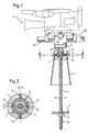
- Fig. 1 shows a preferred embodiment of Balancing system according to the invention for a hand-held camera 11.
- a handle for guiding the camera is a Balance bell 1, tapering in its lower section widened and, for example, aluminum or a other light metal, of plastic, of metal or of a composite material. Due to its conical shape is the balance bell 1 well in the hand.
- a Flange 6 provided at the upper end of the balance bell.
- a handle profile (not ) Shown.
- the conical balance bell 1 offers sufficient pendulum space for a pendulum rod 2.
- This pendulum rod 2 is by means of a gimbal 7 in the balance bell 1 stored so that with respect to the balance bell 1, i. with respect to the handle, in each direction pendulum movements can perform.
- a camera holding mechanism 10 for the camera 11 is attached to the upper end of the pendulum rod 2, so that he also oscillating with respect to the balance bell 1 stored is.
- an outer ring 12 is by means of two screws 14 tiltable with respect to the balance bell 1 stored, and a inner ring 13 is tilted by means of two screws 15 stored with respect to the outer ring 12, wherein the two Rotary axes lie in one plane and an angle of 90 ° form.
- the two rings can be made of aluminum, for example or be made of molded plastic.
- the Pendulum rod 2 passes through the inner ring 13, and two nuts 8 resting on an upper threaded portion 17 the pendulum rod 2 are screwed (see Fig. 1), rest on this inner ring 13 and so keep the pendulum rod. 2 in the gimbal 7.
- Conceivable elements in a suitable manner for example by pinning - on the pendulum rod be attached or integral with the pendulum rod can be trained.
- a counterweight 3 at the lower end of the pendulum rod 2 appropriate.
- the counterweight 3 has a bore, through the pendulum rod 2 extends, and the determination of the Counterweight 3 opposite the pendulum rod 2 by means of a fastening nut 4, which on a lower Threaded portion 5 of the pendulum rod 2 is screwed.
- the Mounting nut 4 can by other suitable Fasteners are replaced, which vary on different Way releasably attached to the pendulum rod 2 can.
- the Counterweight 3 stepless with respect to the pendulum rod 2 be moved.
- the fastening nut 4 be completely unscrewed from the pendulum rod 2, so that the counterweight 3 against another, heavier or lighter counterweight can be replaced.
- the in this embodiment by means of the fastening nut 4th can be adjusted continuously, the balance system exactly the weight of the moment on the camera holding mechanism 10 attached camera 11 are adjusted. Then the camera 11 also retains tilting and tilting movements Balance bell 1 contributes to its balanced position. The tilt and tilting movements may of course only in the Be done area in which the pendulum rod 2 is not the Inner surface of the balance bell 1 touched.
- the cameraman can handle the camera 11 by hand, which does not hold the balance bell 1, by means of a gripping ring 9 with respect to the balance bell 1 about the longitudinal axis of Turn pendulum rod 2 in a controlled manner.
Landscapes
- Engineering & Computer Science (AREA)
- General Engineering & Computer Science (AREA)
- Mechanical Engineering (AREA)
- Accessories Of Cameras (AREA)
- Studio Devices (AREA)
Description
- Fig. 1
- ein erfindungsgemäßes Balancesystem für handgeführte Kameras, und
- Fig. 2
- einen Schnitt entlang der Linie II-II aus Fig. 1.
Claims (15)
- Balancesystem für handgeführte Kameras mit einem Kamera-Haltemechanismus, einem Pendelarm, zumindest einem Kontergewicht und einem Handgriff, wobei das Kontergewicht an den Pendelarm anbringbar und der Pendelarm mit dem Kamera-Haltemechanismus verbunden ist und wobei der Pendelarm an dem Handgriff pendelnd gelagert ist,
dadurch gekennzeichnet, dass
der Handgriff als hohle Balanceglocke (1) ausgeführt ist, die sich zumindest in ihrem in Gebrauchsstellung unteren Abschnitt verbreitert, und dass der Pendelarm eine im wesentlichen gerade Pendelstange (2) ist, die sich durch die Balanceglocke (1) hindurch erstreckt. - Balancesystem nach Anspruch 1, dadurch gekennzeichnet, dass die Pendelstange (2) mittels einer kardanischen Aufhängung (7), die im oberen Teil der Balanceglocke (1) angeordnet ist, pendelnd an der Balanceglocke (1) gelagert ist.
- Balancesystem nach Anspruch 2, dadurch gekennzeichnet, dass die kardanische Aufhängung (7) aus zwei innerhalb der Balanceglocke (1) angeordneten, ineinanderliegenden konzentrischen Ringen (12, 13) besteht, wobei die Pendelstange (2) sich durch den inneren (13) dieser beiden Ringe erstreckt, welcher innere Ring (13) bezüglich des äußeren Rings (12) um eine erste Achse kippbar gelagert ist, wogegen der äußere Ring (12) bezüglich der Balanceglocke (1) um eine zweite Achse kippbar gelagert ist.
- Balancesystem nach mindestens einem der vorangehenden Ansprüche, dadurch gekennzeichnet, dass das Kontergewicht (3) zumindest eine Bohrung aufweist, deren Innendurchmesser etwas größer ist als der Außendurchmesser der Pendelstange (2), so dass das Kontergewicht (3) mittels dieser Bohrung auf die Pendelstange (2) aufschiebbar ist.
- Balancesystem nach mindestens einem der vorangehenden Ansprüche, dadurch gekennzeichnet, dass die Pendelstange (2) zumindest abschnittsweise mit einem Außengewinde (5) versehen ist und dass zumindest eine Befestigungsmutter (4) zum Fixieren des Kontergewichts (3) an der Pendelstange (2) im Bereich dieses Außengewindes (5) anbringbar ist.
- Balancesystem nach mindestens einem der vorangehenden Ansprüche, dadurch gekennzeichnet, dass das Kontergewicht (3) stufenlos entlang der Pendelstange (2) verschiebbar und an jeder beliebigen Stelle entlang der Pendelstange (2) fixierbar ist.
- Balancesystem nach mindestens einem der Ansprüche 1 bis 5, dadurch gekennzeichnet, dass das Kontergewicht (3) entlang der Pendelstange (2) verschiebbar und an vorbestimmten Stellen entlang der Pendelstange (2) fixierbar ist.
- Balancesystem nach mindestens einem der vorangehenden Ansprüche, dadurch gekennzeichnet, dass die Pendelstange (2) Bohrungen aufweist und dass das Kontergewicht (3) mittels Steckstiften, die in diese Bohrungen einsteckbar sind, bezüglich der Pendelstange (2) fixierbar ist.
- Balancesystem nach mindestens einem der vorangehenden Ansprüche, dadurch gekennzeichnet, dass sich zumindest der in Gebrauchsstellung untere Abschnitt der Balanceglocke (1) konisch verbreitert.
- Balancesystem nach Anspruch 9, dadurch gekennzeichnet, dass sich zumindest der in Gebrauchsstellung untere Abschnitt der Balanceglocke (1) gemäß eines Winkels von 5 bis 25° bezüglich der Längsachse der Balanceglocke (1) konisch verbreitert.
- Balancesystem nach mindestens einem der vorangehenden Ansprüche, dadurch gekennzeichnet, dass das Kontergewicht (3) so an der Pendelstange (2) anbringbar ist, dass der Schwerpunkt des Kontergewichts (3) auf der Längsachse der Pendelstange (2) liegt.
- Balancesystem nach mindestens einem der vorangehenden Ansprüche 1-10, dadurch gekennzeichnet, dass das Kontergewicht (3) so an der Pendelstange (2) anbringbar ist, dass der Schwerpunkt des Kontergewichts (3) nicht auf der Längsachse der Pendelstange (2) liegt.
- Balancesystem nach mindestens einem der vorangehenden Ansprüche, dadurch gekennzeichnet, dass der Kamera-Haltemechanismus (10) aus einer fest mit der Pendelstange verbundenen Basis und aus einer Anbringplatte besteht, an der eine Kamera (11) anbringbar ist und die mittels Stellschrauben (16, 18) in Rechts-/Links- und/oder in Vorwärts-/RückwärtsRichtung bezüglich der Basis verschiebbar ist.
- Balancesystem nach mindestens einem der vorangehenden Ansprüche, dadurch gekennzeichnet, dass der Kamera-Haltemechanismus (10) an seiner Unterseite einen zusätzlichen Greifring (9) aufweist, mittels dessen die Kamera (11) gegenüber der Balanceglocke (1) gedreht werden kann.
- Balancesystem nach mindestens einem der vorangehenden Ansprüche, dadurch gekennzeichnet, dass mehrere Kontergewichte (3) vorgesehen sind, von denen eine geeignete Anzahl an der Pendelstange (2) anbringbar ist.
Priority Applications (1)
| Application Number | Priority Date | Filing Date | Title |
|---|---|---|---|
| EP05005857A EP1541917A3 (de) | 2000-12-06 | 2001-11-14 | Balancesystem für handgeführte Kameras |
Applications Claiming Priority (2)
| Application Number | Priority Date | Filing Date | Title |
|---|---|---|---|
| DE10060624 | 2000-12-06 | ||
| DE10060624A DE10060624B4 (de) | 2000-12-06 | 2000-12-06 | Balancesystem für handgeführte Kameras |
Related Child Applications (2)
| Application Number | Title | Priority Date | Filing Date |
|---|---|---|---|
| EP05005857A Division EP1541917A3 (de) | 2000-12-06 | 2001-11-14 | Balancesystem für handgeführte Kameras |
| EP05005857.7 Division-Into | 2005-03-17 |
Publications (2)
| Publication Number | Publication Date |
|---|---|
| EP1213528A1 EP1213528A1 (de) | 2002-06-12 |
| EP1213528B1 true EP1213528B1 (de) | 2005-08-24 |
Family
ID=7666005
Family Applications (2)
| Application Number | Title | Priority Date | Filing Date |
|---|---|---|---|
| EP01126537A Expired - Lifetime EP1213528B1 (de) | 2000-12-06 | 2001-11-14 | Balancesystem für handgeführte Kameras |
| EP05005857A Withdrawn EP1541917A3 (de) | 2000-12-06 | 2001-11-14 | Balancesystem für handgeführte Kameras |
Family Applications After (1)
| Application Number | Title | Priority Date | Filing Date |
|---|---|---|---|
| EP05005857A Withdrawn EP1541917A3 (de) | 2000-12-06 | 2001-11-14 | Balancesystem für handgeführte Kameras |
Country Status (5)
| Country | Link |
|---|---|
| US (1) | US6554500B2 (de) |
| EP (2) | EP1213528B1 (de) |
| JP (1) | JP2002196411A (de) |
| AU (1) | AU779132B2 (de) |
| DE (2) | DE10060624B4 (de) |
Families Citing this family (18)
| Publication number | Priority date | Publication date | Assignee | Title |
|---|---|---|---|---|
| JP3449615B2 (ja) * | 2000-08-21 | 2003-09-22 | 株式会社リオスコーポレーション | 移動体用カメラ取付装置 |
| DE10145197B4 (de) * | 2001-09-13 | 2005-03-03 | Sachtler Gmbh & Co. Kg | Entkoppelter Gewichtsausgleich für eine Kamera-Balance-Vorrichtung |
| DE10145198C1 (de) * | 2001-09-13 | 2003-04-24 | Sachtler Gmbh & Co Kg | Kardanische Aufhängevorrichtung für eine Kamera-Balance-Vorrichtung |
| US6663298B2 (en) * | 2002-02-07 | 2003-12-16 | Todd Gregory Haney | Hand held counter balance and shock absorber camera mount |
| JP2004125029A (ja) * | 2002-10-01 | 2004-04-22 | Nippon Berubon Seiki Kogyo Kk | 雲台 |
| US6808324B2 (en) | 2003-03-12 | 2004-10-26 | Mckay Thomas L. | Image stabilization and balancing system |
| DE20305202U1 (de) * | 2003-04-01 | 2003-08-14 | Buhl, Erich, 42697 Solingen | Schwebestativ zur Ausbalancierung von Kameras |
| US8262037B1 (en) * | 2008-11-03 | 2012-09-11 | Autami Corporation | Automation device and systems packaging and packaging methods for energy management and other applications |
| FR2944507B1 (fr) * | 2009-04-17 | 2011-06-17 | Dcns | Periscope flottant notamment pur un engin sous-marin. |
| US8585205B2 (en) * | 2009-10-07 | 2013-11-19 | Nigel J. Greaves | Gimbaled handle stabilizing controller assembly |
| US8714744B2 (en) * | 2009-10-07 | 2014-05-06 | Nigel J. Greaves | Gimbaled handle stabilizing controller assembly |
| CA2699691A1 (en) | 2010-04-12 | 2011-10-12 | Dennis Wood | Handheld camera balancing support device |
| CN103486412A (zh) * | 2013-08-28 | 2014-01-01 | 苏州国衡机电有限公司 | 一种热合封口机机架平衡调节装置 |
| DE102015115405A1 (de) * | 2015-09-11 | 2017-03-16 | Luuv Forward Gmbh | Stabilisierungsanordnung für Kameras |
| CN107566699A (zh) * | 2017-09-07 | 2018-01-09 | 国家电网公司 | 配网柱上设备智能巡视伸缩云台及其操作方法 |
| US11372318B2 (en) * | 2018-05-29 | 2022-06-28 | Kevin Albert Thomas | Camera gimbal |
| US10844998B2 (en) * | 2018-05-29 | 2020-11-24 | Kevin Albert Thomas | Camera gimbal |
| CN113386944B (zh) * | 2021-07-19 | 2022-07-08 | 武汉中科立维信息工程有限公司 | 一种基于传感器pos与imu耦合器的无人机 |
Citations (1)
| Publication number | Priority date | Publication date | Assignee | Title |
|---|---|---|---|---|
| EP0360268A2 (de) * | 1988-09-22 | 1990-03-28 | BROWN, Garrett W. | Stabilisierter Gerätehalter, insbesondere für Leichtbau-Kameras |
Family Cites Families (8)
| Publication number | Priority date | Publication date | Assignee | Title |
|---|---|---|---|---|
| US2007215A (en) * | 1931-11-12 | 1935-07-09 | John T Remey | Stabilized vibration absorbing mounting |
| FR2611855B1 (fr) * | 1987-03-03 | 1989-07-13 | Spianti Dany | Support d'equipement portatif, notamment de camera |
| US5229798A (en) * | 1988-09-22 | 1993-07-20 | Brown Garrett W | Stabilized equipment support, primarily for use with hand-held cameras |
| WO1996015404A1 (en) * | 1994-11-14 | 1996-05-23 | Thompson Michael William Fleet | Body-mounted stabilising apparatus for a camera |
| US5650821A (en) * | 1995-05-09 | 1997-07-22 | Hewlett; Kenneth | Video camera support with counterbalance |
| SE9600430L (sv) * | 1996-02-06 | 1997-03-10 | Elias Staicouras | Kamerastabilisator |
| JPH10232446A (ja) * | 1997-02-19 | 1998-09-02 | Biinoi:Kk | カメラ支持装置 |
| US5963749A (en) * | 1998-02-09 | 1999-10-05 | Nicholson; Lynn | Self-leveling invertible camera stabilizer |
-
2000
- 2000-12-06 DE DE10060624A patent/DE10060624B4/de not_active Expired - Fee Related
-
2001
- 2001-11-14 DE DE50107190T patent/DE50107190D1/de not_active Expired - Fee Related
- 2001-11-14 EP EP01126537A patent/EP1213528B1/de not_active Expired - Lifetime
- 2001-11-14 EP EP05005857A patent/EP1541917A3/de not_active Withdrawn
- 2001-11-27 AU AU93442/01A patent/AU779132B2/en not_active Ceased
- 2001-12-05 JP JP2001371985A patent/JP2002196411A/ja not_active Ceased
- 2001-12-06 US US10/008,984 patent/US6554500B2/en not_active Expired - Fee Related
Patent Citations (1)
| Publication number | Priority date | Publication date | Assignee | Title |
|---|---|---|---|---|
| EP0360268A2 (de) * | 1988-09-22 | 1990-03-28 | BROWN, Garrett W. | Stabilisierter Gerätehalter, insbesondere für Leichtbau-Kameras |
Also Published As
| Publication number | Publication date |
|---|---|
| AU779132B2 (en) | 2005-01-06 |
| DE50107190D1 (de) | 2005-09-29 |
| EP1541917A2 (de) | 2005-06-15 |
| DE10060624A1 (de) | 2002-06-20 |
| US20020090216A1 (en) | 2002-07-11 |
| US6554500B2 (en) | 2003-04-29 |
| EP1213528A1 (de) | 2002-06-12 |
| AU9344201A (en) | 2002-06-13 |
| EP1541917A3 (de) | 2006-05-17 |
| JP2002196411A (ja) | 2002-07-12 |
| DE10060624B4 (de) | 2006-08-24 |
Similar Documents
| Publication | Publication Date | Title |
|---|---|---|
| DE10060624B4 (de) | Balancesystem für handgeführte Kameras | |
| DE4231516C2 (de) | Stativ für Operationsmikroskop mit Drehmomentausgleich | |
| EP0433426A1 (de) | Mit zusatzvorrichtungen ausgestattetes stativ für die halterung eines frei positionierbaren gerätes. | |
| DE202015007728U1 (de) | Stelleinrichtung | |
| DE2852034A1 (de) | Kamerastativ | |
| DE10145197B4 (de) | Entkoppelter Gewichtsausgleich für eine Kamera-Balance-Vorrichtung | |
| DE7315186U (de) | Verstellbares stativ fuer ein optisches beobachtungsgeraet, insbesondere ein binokularmikroskop | |
| DE10145198C1 (de) | Kardanische Aufhängevorrichtung für eine Kamera-Balance-Vorrichtung | |
| DE8800888U1 (de) | Handhabungsgerät zum Transportieren und Positionieren von Gegenständen | |
| EP1309815B1 (de) | Träger zum tragen von zumindest einem apparat | |
| DE10145199B4 (de) | Kardanische Aufhängevorrichtung für eine Kamera-Balance-Vorrichtung | |
| DE10136341A1 (de) | Balancesystem mit Rollgriff für handgefütterte Kameras | |
| DE3802166C2 (de) | ||
| DE3834251A1 (de) | Instrumententragsaeule | |
| DE20023624U1 (de) | Balancesystem für handgeführte Kameras | |
| DE19742051A1 (de) | Stativ mit Energiespeicher zum Gewichtsausgleich | |
| EP1123859A2 (de) | Sattelträger | |
| DE10222663B4 (de) | Gerätekran, insbesondere Kamerakran | |
| DE1217091C2 (de) | Antiskatingvorrichtung | |
| DE10326978B4 (de) | Kreuzgelenk | |
| DE20122466U1 (de) | Balancesystem mit Rollgriff für handgeführte Karmeras | |
| DE2320266C3 (de) | Verstellbares Stativ für ein optisches Beobachtungsgerät, insbesondere ein Binokularmikroskop | |
| DE29819493U1 (de) | Stativaufsatz | |
| DE9219240U1 (de) | Operationsmikroskop mit Drehmomentausgleich | |
| DE3633458A1 (de) | Kolbenformmaschine mit rohlingsbeschickungsvorrichtung |
Legal Events
| Date | Code | Title | Description |
|---|---|---|---|
| PUAI | Public reference made under article 153(3) epc to a published international application that has entered the european phase |
Free format text: ORIGINAL CODE: 0009012 |
|
| AK | Designated contracting states |
Kind code of ref document: A1 Designated state(s): AT BE CH CY DE DK ES FI FR GB GR IE IT LI LU MC NL PT SE TR |
|
| AX | Request for extension of the european patent |
Free format text: AL;LT;LV;MK;RO;SI |
|
| 17P | Request for examination filed |
Effective date: 20020828 |
|
| AKX | Designation fees paid |
Designated state(s): DE FR GB IT |
|
| 17Q | First examination report despatched |
Effective date: 20050113 |
|
| GRAP | Despatch of communication of intention to grant a patent |
Free format text: ORIGINAL CODE: EPIDOSNIGR1 |
|
| GRAS | Grant fee paid |
Free format text: ORIGINAL CODE: EPIDOSNIGR3 |
|
| GRAA | (expected) grant |
Free format text: ORIGINAL CODE: 0009210 |
|
| RAP1 | Party data changed (applicant data changed or rights of an application transferred) |
Owner name: SACHTLER GMBH & CO. KG |
|
| AK | Designated contracting states |
Kind code of ref document: B1 Designated state(s): DE FR GB IT |
|
| REG | Reference to a national code |
Ref country code: GB Ref legal event code: FG4D Free format text: NOT ENGLISH |
|
| GBT | Gb: translation of ep patent filed (gb section 77(6)(a)/1977) |
Effective date: 20050824 |
|
| REF | Corresponds to: |
Ref document number: 50107190 Country of ref document: DE Date of ref document: 20050929 Kind code of ref document: P |
|
| ET | Fr: translation filed | ||
| PLBE | No opposition filed within time limit |
Free format text: ORIGINAL CODE: 0009261 |
|
| STAA | Information on the status of an ep patent application or granted ep patent |
Free format text: STATUS: NO OPPOSITION FILED WITHIN TIME LIMIT |
|
| 26N | No opposition filed |
Effective date: 20060526 |
|
| PGFP | Annual fee paid to national office [announced via postgrant information from national office to epo] |
Ref country code: DE Payment date: 20071126 Year of fee payment: 7 |
|
| PGFP | Annual fee paid to national office [announced via postgrant information from national office to epo] |
Ref country code: IT Payment date: 20071107 Year of fee payment: 7 |
|
| REG | Reference to a national code |
Ref country code: FR Ref legal event code: TP Ref country code: FR Ref legal event code: CD |
|
| PGFP | Annual fee paid to national office [announced via postgrant information from national office to epo] |
Ref country code: FR Payment date: 20071115 Year of fee payment: 7 Ref country code: GB Payment date: 20071114 Year of fee payment: 7 |
|
| GBPC | Gb: european patent ceased through non-payment of renewal fee |
Effective date: 20081114 |
|
| PG25 | Lapsed in a contracting state [announced via postgrant information from national office to epo] |
Ref country code: IT Free format text: LAPSE BECAUSE OF NON-PAYMENT OF DUE FEES Effective date: 20081114 |
|
| REG | Reference to a national code |
Ref country code: FR Ref legal event code: ST Effective date: 20090731 |
|
| PG25 | Lapsed in a contracting state [announced via postgrant information from national office to epo] |
Ref country code: DE Free format text: LAPSE BECAUSE OF NON-PAYMENT OF DUE FEES Effective date: 20090603 |
|
| PG25 | Lapsed in a contracting state [announced via postgrant information from national office to epo] |
Ref country code: GB Free format text: LAPSE BECAUSE OF NON-PAYMENT OF DUE FEES Effective date: 20081114 |
|
| PG25 | Lapsed in a contracting state [announced via postgrant information from national office to epo] |
Ref country code: FR Free format text: LAPSE BECAUSE OF NON-PAYMENT OF DUE FEES Effective date: 20081130 |