EP1213191B1 - Instrumententafeln für Kraftfahrzeuge - Google Patents
Instrumententafeln für Kraftfahrzeuge Download PDFInfo
- Publication number
- EP1213191B1 EP1213191B1 EP01126162A EP01126162A EP1213191B1 EP 1213191 B1 EP1213191 B1 EP 1213191B1 EP 01126162 A EP01126162 A EP 01126162A EP 01126162 A EP01126162 A EP 01126162A EP 1213191 B1 EP1213191 B1 EP 1213191B1
- Authority
- EP
- European Patent Office
- Prior art keywords
- foam body
- mold carrier
- foam
- dashboard
- motor vehicle
- Prior art date
- Legal status (The legal status is an assumption and is not a legal conclusion. Google has not performed a legal analysis and makes no representation as to the accuracy of the status listed.)
- Expired - Lifetime
Links
Images
Classifications
-
- B—PERFORMING OPERATIONS; TRANSPORTING
- B60—VEHICLES IN GENERAL
- B60R—VEHICLES, VEHICLE FITTINGS, OR VEHICLE PARTS, NOT OTHERWISE PROVIDED FOR
- B60R21/00—Arrangements or fittings on vehicles for protecting or preventing injuries to occupants or pedestrians in case of accidents or other traffic risks
- B60R21/02—Occupant safety arrangements or fittings, e.g. crash pads
- B60R21/04—Padded linings for the vehicle interior ; Energy absorbing structures associated with padded or non-padded linings
- B60R21/045—Padded linings for the vehicle interior ; Energy absorbing structures associated with padded or non-padded linings associated with the instrument panel or dashboard
-
- B—PERFORMING OPERATIONS; TRANSPORTING
- B60—VEHICLES IN GENERAL
- B60K—ARRANGEMENT OR MOUNTING OF PROPULSION UNITS OR OF TRANSMISSIONS IN VEHICLES; ARRANGEMENT OR MOUNTING OF PLURAL DIVERSE PRIME-MOVERS IN VEHICLES; AUXILIARY DRIVES FOR VEHICLES; INSTRUMENTATION OR DASHBOARDS FOR VEHICLES; ARRANGEMENTS IN CONNECTION WITH COOLING, AIR INTAKE, GAS EXHAUST OR FUEL SUPPLY OF PROPULSION UNITS IN VEHICLES
- B60K37/00—Dashboards
- B60K37/20—Dashboard panels
-
- B—PERFORMING OPERATIONS; TRANSPORTING
- B60—VEHICLES IN GENERAL
- B60K—ARRANGEMENT OR MOUNTING OF PROPULSION UNITS OR OF TRANSMISSIONS IN VEHICLES; ARRANGEMENT OR MOUNTING OF PLURAL DIVERSE PRIME-MOVERS IN VEHICLES; AUXILIARY DRIVES FOR VEHICLES; INSTRUMENTATION OR DASHBOARDS FOR VEHICLES; ARRANGEMENTS IN CONNECTION WITH COOLING, AIR INTAKE, GAS EXHAUST OR FUEL SUPPLY OF PROPULSION UNITS IN VEHICLES
- B60K2360/00—Indexing scheme associated with groups B60K35/00 or B60K37/00 relating to details of instruments or dashboards
- B60K2360/60—Structural details of dashboards or instruments
- B60K2360/65—Features of dashboards
- B60K2360/658—Dashboard parts used as air ducts
Definitions
- the invention relates to a method for producing instrument panels according to the preamble of claim 1.
- An instrument panel for motor vehicles is known from FR 2 729 913 A1 consists of a mold carrier and a foam body provided on this.
- the foam body is in turn covered by a cover, with differently shaped foam body of the mold carrier each formally is of the same design.
- an instrument panel is disclosed in DE 36 20 881 C2 that one off Plastic existing mold carrier and one provided on this Has foam body, which in turn is provided with a cover.
- the shape structure of the mold carrier is adapted to the respective foam body become. Therefore, for the production of a mold carrier made of plastic In each case, an injection molding tool provided for this is required.
- the object of the invention is therefore a method for producing a To create instrument panel for motor vehicles, being a mold carrier very is inexpensive to manufacture.
- the mold carrier is always designed in the same way on the peripheral contours, so that for its manufacture advantageously only a single tool - namely Injection molding or sheet metal forming tool - is required, the on the
- the foam body provided for the mold carrier nevertheless has a different external shape can have.
- instrument panels are each a different one Have external shape, very inexpensive to manufacture.
- it follows also a lower number of parts and a slight reduction in weight.
- At least one groove-like serves in the mold carrier and / or in the foam body Depression as an air duct.
- This has a groove-like formation Deepening in the mold carrier and in the foam body and when the Wells to each other a high air flow. This also makes it very formed an air duct in a simple and reliable manner.
- a method for producing an instrument panel is according to the invention in that while foaming one in turn with the cover connected foam layer on the foam body in the air duct an excess pressure is introduced, which is advantageously about 2 to 4 bar. This measure ensures that on the outside of the cover no unsightly depressions (sink marks) in the area of the air duct arise.
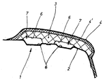
- the instrument panel 1 shown in the drawing is located in a passenger car and consists of a plastic carrier 2 and from a prefabricated foam body 3, which is attached to the mold carrier 3 is.
- the foam body 3 is in turn made of a polyurethane Foam layer 4 'covered, which in turn with a film-like cover 4th connected is.
- the foam body 3 can vary in thickness and width as well as in the design be formed, but the mold carrier 2 is always the same designed in terms of shape and can therefore always be manufactured using the same injection molding tool is.
- both in the mold carrier 2 and in the foam body 3 each formed two longitudinal, groove-like depressions 6, the are facing each other and each have an air duct 7 with large Form air flow.
- the foam body 3 is a prefabricated part directly on the mold carrier 2 attached. To ensure that on the outside of the cover 4 in Area of the air duct 7 do not form sink marks during the foaming the foam layer 4 'on the foam body 3 in the air duct 7 initiated an air pressure of about 2 to 4 bar.
Landscapes
- Engineering & Computer Science (AREA)
- Mechanical Engineering (AREA)
- Chemical & Material Sciences (AREA)
- Combustion & Propulsion (AREA)
- Transportation (AREA)
- Instrument Panels (AREA)
- Injection Moulding Of Plastics Or The Like (AREA)
- Casting Or Compression Moulding Of Plastics Or The Like (AREA)
Description
Claims (2)
- Verfahren zum Herstellen einer Instrumententafel (1), mit mindestens einem Formträger (2) sowie wenigstens einem auf diesem vorgesehenen Schaumkörper (3), und mit mindestens einem, im Schaumkörper (3) und / oder im Formträger (2) ausgebildeten Luftführungskanal (7), wobei auf den Schaumkörper (3) eine ihrerseits von einer Abdeckung (4) überdeckte Schaumstoffschicht (4') aufgeschäumt wird, dadurch gekennzeichnet, dass während des Aufschäumens der Schaumstoffschicht (4') auf den Schaumkörper (3) in den Luftführungskanal (7) ein Luftüberdruck eingeleitet wird.
- Verfahren nach Anspruch 1, dadurch gekennzeichnet, dass in den Luftführungskanal(7) ein Luftüberdruck von etwa 2 bis 4 bar eingeleitet wird.
Applications Claiming Priority (2)
| Application Number | Priority Date | Filing Date | Title |
|---|---|---|---|
| DE10060537A DE10060537A1 (de) | 2000-12-06 | 2000-12-06 | Instrumententafeln für Kraftfahrzeuge |
| DE10060537 | 2000-12-06 |
Publications (3)
| Publication Number | Publication Date |
|---|---|
| EP1213191A2 EP1213191A2 (de) | 2002-06-12 |
| EP1213191A3 EP1213191A3 (de) | 2002-08-07 |
| EP1213191B1 true EP1213191B1 (de) | 2004-08-18 |
Family
ID=7665949
Family Applications (1)
| Application Number | Title | Priority Date | Filing Date |
|---|---|---|---|
| EP01126162A Expired - Lifetime EP1213191B1 (de) | 2000-12-06 | 2001-11-03 | Instrumententafeln für Kraftfahrzeuge |
Country Status (3)
| Country | Link |
|---|---|
| EP (1) | EP1213191B1 (de) |
| DE (2) | DE10060537A1 (de) |
| ES (1) | ES2223707T3 (de) |
Cited By (1)
| Publication number | Priority date | Publication date | Assignee | Title |
|---|---|---|---|---|
| DE102013019388A1 (de) | 2013-11-18 | 2015-05-21 | GM Global Technology Operations LLC (n. d. Ges. d. Staates Delaware) | Instrumententafel für ein Fahrzeug, Fahrzeug mit der Instrumententafel und Verfahren zur Herstellung der Instrumententafel |
Families Citing this family (4)
| Publication number | Priority date | Publication date | Assignee | Title |
|---|---|---|---|---|
| DE10258705A1 (de) * | 2002-12-11 | 2004-07-15 | Sai Automotive Sal Gmbh | Wandstruktur und Verfahren zu deren Herstellung |
| DE102006050820B4 (de) * | 2006-10-27 | 2019-03-07 | Audi Ag | Hutablage |
| DE102007056334B4 (de) | 2007-11-22 | 2019-03-14 | Volkswagen Ag | Verfahren zum Herstellen einer Instrumententafel und Instrumententafel eines Fahrzeugs |
| FR2964084B1 (fr) * | 2010-08-24 | 2012-10-05 | Airbus Operations Sas | Support de dispositifs d'affichage pour un poste de pilotage d'aeronef |
Family Cites Families (6)
| Publication number | Priority date | Publication date | Assignee | Title |
|---|---|---|---|---|
| DE3620881A1 (de) * | 1986-06-21 | 1988-01-14 | Audi Ag | Innenausstattungselement fuer den fahrgastraum eines kraftfahrzeuges |
| US5190803A (en) * | 1988-11-25 | 1993-03-02 | Bayer Aktiengesellschaft | Structural shell with reinforcing ribs connected via perforations |
| DE4028986A1 (de) * | 1990-09-13 | 1992-03-19 | Bayerische Motoren Werke Ag | Innenausstattungsteil, insbesondere armaturentafel oder hutablage eines kraftfahrzeuges |
| DE4227292A1 (de) * | 1991-08-20 | 1993-01-14 | Wilfried Wagner | Oberflaechen von bauteilen die der waermeeinstrahlung ausgesetzt sind, insbesondere der armaturenabdeckung in kraftfahrzeugen |
| DE4204495C2 (de) * | 1992-02-14 | 1994-07-21 | Daimler Benz Ag | Am Fahrzeugaufbau festgelegter Armaturenträger |
| FR2729913B1 (fr) * | 1995-02-01 | 1997-04-30 | Ecia Equip Composants Ind Auto | Procede de fabrication d'une piece d'equipement notamment d'un vehicule automobile et planche de bord fabriquee selon ce procede |
-
2000
- 2000-12-06 DE DE10060537A patent/DE10060537A1/de not_active Withdrawn
-
2001
- 2001-11-03 DE DE50103303T patent/DE50103303D1/de not_active Expired - Lifetime
- 2001-11-03 ES ES01126162T patent/ES2223707T3/es not_active Expired - Lifetime
- 2001-11-03 EP EP01126162A patent/EP1213191B1/de not_active Expired - Lifetime
Cited By (3)
| Publication number | Priority date | Publication date | Assignee | Title |
|---|---|---|---|---|
| DE102013019388A1 (de) | 2013-11-18 | 2015-05-21 | GM Global Technology Operations LLC (n. d. Ges. d. Staates Delaware) | Instrumententafel für ein Fahrzeug, Fahrzeug mit der Instrumententafel und Verfahren zur Herstellung der Instrumententafel |
| CN104648302A (zh) * | 2013-11-18 | 2015-05-27 | 通用汽车环球科技运作有限责任公司 | 汽车的仪表盘、具有该仪表盘的汽车和该仪表盘的制造方法 |
| CN104648302B (zh) * | 2013-11-18 | 2018-11-16 | 通用汽车环球科技运作有限责任公司 | 仪表盘、具有该仪表盘的汽车和该仪表盘的制造方法 |
Also Published As
| Publication number | Publication date |
|---|---|
| ES2223707T3 (es) | 2005-03-01 |
| DE10060537A1 (de) | 2002-06-20 |
| DE50103303D1 (de) | 2004-09-23 |
| EP1213191A3 (de) | 2002-08-07 |
| EP1213191A2 (de) | 2002-06-12 |
Similar Documents
| Publication | Publication Date | Title |
|---|---|---|
| DE10120267B4 (de) | Verfahren zur Herstellung eines Mehrfachschaumstoff-Innenverkleidungssubstrats | |
| DE69627772T2 (de) | Innenbekleidung für Kraftfahrzeuge mit integrierter Luftkanal | |
| DE19929971B4 (de) | Kraftfahrzeugtür-Innenverkleidung | |
| EP0710578B1 (de) | Verkleidungsteil, insbesondere Türverkleidungsträger, für ein Kraftfahrzeug | |
| DE102005019685A1 (de) | Emblem für ein Kraftfahrzeug | |
| DE10100745A1 (de) | In der Form laminiertes Bauteil und Verfahren zu seiner Herstellung | |
| EP1602549B1 (de) | Lenkrad für ein Kraftfahrzeug | |
| DE60106159T2 (de) | Giessen eines Plastikteils mit weicher Oberfläche | |
| DE102005037003A1 (de) | Fahrzeuginnenausstattungsteil, das eine gespritzte Schicht aus expandiertem Polyurethan aufweist, und Verfahren und System zu dessen Herstellung | |
| DE102016103745A1 (de) | Formwerkzeug zum Fixieren eines Einsatzes in einer Ausnehmung eines tafelartigen Werkstücks sowie Fahrzeugdachelement | |
| DE10352581A1 (de) | Innenverkleidungsteil, insbesondere Instrumententafel für ein Kraftfahrzeug | |
| EP1318009A1 (de) | Mehrschicht-Formteil, insbesondere Innenraum-Teil für ein Kraftfahrzeug, sowie Verfahren zur Herstellung des Formteils | |
| DE3804619A1 (de) | Kunststofformling mit mehreren bereichen aus unterschiedlichem polyurethan | |
| EP1213191A2 (de) | Instrumententafeln für Kraftfahrzeuge | |
| DE2052907A1 (en) | Moulding foamed plastics seats - esp for automobiles having differing local properties | |
| DE19837104A1 (de) | Verfahren zur Herstellung von Kunststofftankklappen für Kraftfahrzeuge | |
| DE202015101955U1 (de) | Spritzgegossene Wasserablaufleiste und Anordnung für eine Fahrzeugverkleidung | |
| DE19754137A1 (de) | Verkleidungsteil für einen Airbag in einem Kraftfahrzeug | |
| EP1199226B1 (de) | Herstellverfahren für ein Fahrzeug-Innenausstattungsteil mit einer Airbag-Aufreissnaht | |
| DE19751759C1 (de) | Verfahren zur Herstellung einer Verbundwanne | |
| EP1663613A1 (de) | Verfahren und vorrichtung zur herstellung einer abdeckung für einen airbag in einem kraftfahrzeug | |
| EP1897729B1 (de) | Bewegliches Fahrzeugdach | |
| DE19944351C1 (de) | Leiste aus Kunststoff sowie ein Verfahren zu ihrer Herstellung | |
| DE102005024776A1 (de) | Verfahren zum Herstellen eines Kunststoffverbundteils | |
| DE102004020690B4 (de) | Verfahren zum Herstellen eines Innenverkleidungsteils und Innenverkleidungsteil |
Legal Events
| Date | Code | Title | Description |
|---|---|---|---|
| PUAI | Public reference made under article 153(3) epc to a published international application that has entered the european phase |
Free format text: ORIGINAL CODE: 0009012 |
|
| AK | Designated contracting states |
Kind code of ref document: A2 Designated state(s): AT BE CH CY DE DK ES FI FR GB GR IE IT LI LU MC NL PT SE TR |
|
| AX | Request for extension of the european patent |
Free format text: AL;LT;LV;MK;RO;SI |
|
| PUAL | Search report despatched |
Free format text: ORIGINAL CODE: 0009013 |
|
| AK | Designated contracting states |
Kind code of ref document: A3 Designated state(s): AT BE CH CY DE DK ES FI FR GB GR IE IT LI LU MC NL PT SE TR |
|
| AX | Request for extension of the european patent |
Free format text: AL;LT;LV;MK;RO;SI |
|
| RIC1 | Information provided on ipc code assigned before grant |
Free format text: 7B 60R 21/045 A, 7B 60K 37/00 B |
|
| 17P | Request for examination filed |
Effective date: 20030122 |
|
| AKX | Designation fees paid |
Designated state(s): DE ES FR GB IT |
|
| 17Q | First examination report despatched |
Effective date: 20030521 |
|
| GRAP | Despatch of communication of intention to grant a patent |
Free format text: ORIGINAL CODE: EPIDOSNIGR1 |
|
| GRAS | Grant fee paid |
Free format text: ORIGINAL CODE: EPIDOSNIGR3 |
|
| GRAA | (expected) grant |
Free format text: ORIGINAL CODE: 0009210 |
|
| AK | Designated contracting states |
Kind code of ref document: B1 Designated state(s): DE ES FR GB IT |
|
| REG | Reference to a national code |
Ref country code: GB Ref legal event code: FG4D Free format text: NOT ENGLISH |
|
| GBT | Gb: translation of ep patent filed (gb section 77(6)(a)/1977) |
Effective date: 20040818 |
|
| REG | Reference to a national code |
Ref country code: IE Ref legal event code: FG4D Free format text: GERMAN |
|
| REF | Corresponds to: |
Ref document number: 50103303 Country of ref document: DE Date of ref document: 20040923 Kind code of ref document: P |
|
| ET | Fr: translation filed | ||
| REG | Reference to a national code |
Ref country code: ES Ref legal event code: FG2A Ref document number: 2223707 Country of ref document: ES Kind code of ref document: T3 |
|
| REG | Reference to a national code |
Ref country code: IE Ref legal event code: FD4D |
|
| PLBE | No opposition filed within time limit |
Free format text: ORIGINAL CODE: 0009261 |
|
| STAA | Information on the status of an ep patent application or granted ep patent |
Free format text: STATUS: NO OPPOSITION FILED WITHIN TIME LIMIT |
|
| 26N | No opposition filed |
Effective date: 20050519 |
|
| PGFP | Annual fee paid to national office [announced via postgrant information from national office to epo] |
Ref country code: GB Payment date: 20131128 Year of fee payment: 13 Ref country code: DE Payment date: 20131115 Year of fee payment: 13 |
|
| PGFP | Annual fee paid to national office [announced via postgrant information from national office to epo] |
Ref country code: ES Payment date: 20131018 Year of fee payment: 13 Ref country code: FR Payment date: 20131127 Year of fee payment: 13 Ref country code: IT Payment date: 20131127 Year of fee payment: 13 |
|
| REG | Reference to a national code |
Ref country code: DE Ref legal event code: R119 Ref document number: 50103303 Country of ref document: DE |
|
| GBPC | Gb: european patent ceased through non-payment of renewal fee |
Effective date: 20141103 |
|
| REG | Reference to a national code |
Ref country code: FR Ref legal event code: ST Effective date: 20150731 |
|
| PG25 | Lapsed in a contracting state [announced via postgrant information from national office to epo] |
Ref country code: GB Free format text: LAPSE BECAUSE OF NON-PAYMENT OF DUE FEES Effective date: 20141103 Ref country code: DE Free format text: LAPSE BECAUSE OF NON-PAYMENT OF DUE FEES Effective date: 20150602 |
|
| PG25 | Lapsed in a contracting state [announced via postgrant information from national office to epo] |
Ref country code: FR Free format text: LAPSE BECAUSE OF NON-PAYMENT OF DUE FEES Effective date: 20141201 |
|
| PG25 | Lapsed in a contracting state [announced via postgrant information from national office to epo] |
Ref country code: IT Free format text: LAPSE BECAUSE OF NON-PAYMENT OF DUE FEES Effective date: 20141103 |
|
| REG | Reference to a national code |
Ref country code: ES Ref legal event code: FD2A Effective date: 20160104 |
|
| PG25 | Lapsed in a contracting state [announced via postgrant information from national office to epo] |
Ref country code: ES Free format text: LAPSE BECAUSE OF NON-PAYMENT OF DUE FEES Effective date: 20141104 |