EP1213063A2 - Sickenmaschine - Google Patents
Sickenmaschine Download PDFInfo
- Publication number
- EP1213063A2 EP1213063A2 EP01811126A EP01811126A EP1213063A2 EP 1213063 A2 EP1213063 A2 EP 1213063A2 EP 01811126 A EP01811126 A EP 01811126A EP 01811126 A EP01811126 A EP 01811126A EP 1213063 A2 EP1213063 A2 EP 1213063A2
- Authority
- EP
- European Patent Office
- Prior art keywords
- beading
- tools
- machine according
- turntable
- machine
- Prior art date
- Legal status (The legal status is an assumption and is not a legal conclusion. Google has not performed a legal analysis and makes no representation as to the accuracy of the status listed.)
- Granted
Links
Images
Classifications
-
- B—PERFORMING OPERATIONS; TRANSPORTING
- B21—MECHANICAL METAL-WORKING WITHOUT ESSENTIALLY REMOVING MATERIAL; PUNCHING METAL
- B21D—WORKING OR PROCESSING OF SHEET METAL OR METAL TUBES, RODS OR PROFILES WITHOUT ESSENTIALLY REMOVING MATERIAL; PUNCHING METAL
- B21D17/00—Forming single grooves in sheet metal or tubular or hollow articles
- B21D17/04—Forming single grooves in sheet metal or tubular or hollow articles by rolling
Definitions
- the invention relates to a beading machine for processing of sheet metal, with a machine frame on which at least two driven beading tools spaced from each other are.
- Beading machines have long been known in the prior art. They deform a sheet between work rolls by progressive Bend in an edge direction. Beads serve in particular for stiffening metal sheets or for connecting one another inserted parts.
- the sheet, pipe or the like to be processed moves when beading between two rollers that form the profile the bead. Both roles are powered and take the sheet with.
- By adjusting at least one beading roller Beading tool or by changing the beading tool different beads can be produced.
- a beading machine the two on a common Has shaft arranged beading tools. These sikken tools can be set differently. Depending on The bead to be produced now becomes one or the other Tool used.
- the invention has for its object a beading machine of the type mentioned to create an even more rational editing of sheet metal.
- the invention is in a generic beading machine solved that the beading tools on a common Rotary table are arranged and by rotating the rotary table each are movable to the same working position.
- the Beading machine is in a single working position machining a sheet with each of the beading tools possible.
- the work position does not have to be left, when changing to another beading tool.
- a simpler and faster processing is possible and on the other hand, the space requirement is much smaller because only accessibility to a single work position is required.
- the beading machine according to the invention can therefore For example, be arranged in a corner of the room and however, there may be three or more beading tools and can be used optionally.
- beading tools these are preferably arranged in the corners of a triangle. At the The rotary table then only has to change the beading tool rotated 120 degrees in one direction or the other become.
- the beading tools can, for example, beading rolls be, but each set different are. Different beading tools are also conceivable here.
- each Beading tool with a single common drive can be disengaged, so a simple structure is possible and in addition, only the beading tool used is driven, which is advantageous in terms of occupational safety is. When working, the unused Sikken tools are always there quiet.
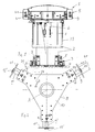
- the beading machine 1 has a machine frame 2 on, which has three drives 3 at its lower end and on a building floor 32 is provided.
- the drives 3 each have on a holder 5 a height-adjustable roller 4.
- the beading machine 1 can be parked on the floor 32 or in the raised state.
- a drive unit 6 is arranged on the machine frame 2 has an electric motor 7 or another suitable motor.
- the drive axis A of this drive unit 6 runs vertically and centrally to a turntable 8, which according to FIG. 2 in equidistant from each other and peripherally three bead units 9, 9 'and 9' '.
- the turntable 8 is about the axis A. rotatably mounted on the machine frame 2. 2 shows with the double arrow 34 the directions of rotation in which the turntable 8 can be rotated around axis A indefinitely.
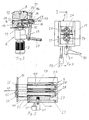
- the drive unit 6 has a bearing block 17 on, which is firmly connected to the machine frame 2 and in which a bevel gear 35 is used.
- This gear 35 is made essentially of a bevel gear 14 which is fixed to a vertical drive shaft 15 is connected and three more Bevel gears 18, each fixed to a clutch shaft 16 are connected and each mesh with the bevel gear 14.
- In 3 are only a bevel gear 18 and two clutch shafts 16 visible.
- the three coupling shafts 16 are star-shaped arranged and the angle between adjacent coupling shafts 16 is 120 degrees.
- versions are also conceivable here, where only two clutch shafts or more than three clutch shafts 16 are provided.
- the arrangement is however here preferably symmetrical and all shafts 13 become common driven by the shaft 15.
- the coupling shafts 16 each protrude with an outer end the bearing block 17, as shown in FIG. 3.
- a coupling piece 36 mounted slidably. through a clutch lever 19 at its upper end 19a a trestle is pivotally mounted and at its lower free end has a locking handle 20, the coupling piece 36 adjusted in the directions of the double arrow 38 limited become.
- Each of the shafts 16 can be pivoted by pivoting the clutch lever 19 with appropriate positioning of the rotary table 8 one of the bead units 9, 9 'or 9' 'can be coupled.
- the Coupling piece 36 is for this purpose from the position shown in Fig. 3 moved radially outwards.
- clutch claws engage 28 between corresponding clutch claws 28 of a gear 27, which is firmly connected to a shaft 25 of a beading roller 21 is.
- the wheel 27 meshes with a gear 26, which with a upper shaft 24 of the upper bead 22 is connected.
- the two beading rollers 21 and 22 are supported in a bearing block 39, on which a stop plate 11 is radially adjustable is.
- the stop plate 11 engages with a web 40 in one here Not shown recess of the bearing block 39 and can in each position can be clamped by means of a clamping member 31.
- the two beading rollers 21 and 22 pass through the stop plate 11.
- 9 'or 9 is preferably such a stop plate 11 is provided.
- the two beading rollers 21 and 22 are designed as known per se. Other beading tools can also be provided here his.
- a sheet 41 to be machined is known per se Inserted between the running beads 21 and 22, as indicated in FIG. 5.
- the sheet 21 can also be a pipe or a lid. This is, for example, according to Fig. 2 processed in the two o'clock position with the bead unit 9. Now this piece of sheet metal 41 or another piece of sheet metal processed with the bead unit 9 ', so the bead unit 9 disengaged and the turntable 8 is turned counterclockwise rotated by 120 degrees. The bead unit 9 'is located now in two o'clock position. All bead units 9, 9 ', or 9 '' are not driven.
- the bead unit 9 'with the drive unit 6 coupled and the plate 41 can also can be processed in the two o'clock position with the bead unit 9 '. If the bead unit 9 'is no longer required, it will uncoupled and the rotary table 8 can now optionally be clockwise or counterclockwise. A turning of the Turntable 8 is only possible if all the bead units 9, 9 'and 9' 'are uncoupled. This ensures that during processing only the bead unit 9, 9 'or 9' ' is driven, which is required for processing a sheet 41 becomes.
Landscapes
- Engineering & Computer Science (AREA)
- Mechanical Engineering (AREA)
- Preliminary Treatment Of Fibers (AREA)
- Tyre Moulding (AREA)
- Processing And Handling Of Plastics And Other Materials For Molding In General (AREA)
- Confectionery (AREA)
- Glass Compositions (AREA)
- Permanent Magnet Type Synchronous Machine (AREA)
- Formation And Processing Of Food Products (AREA)
- Yarns And Mechanical Finishing Of Yarns Or Ropes (AREA)
- Bending Of Plates, Rods, And Pipes (AREA)
Abstract
Description
- Fig 1
- schematisch eine Ansicht einer erfindungsgemässen Sickenmaschine wobei Teile aus zeichnerischen Gründen weggelassen sind,
- Fig. 2
- eine Draufsicht auf die erfindungsgemässe Sickenmaschine,
- Fig. 3
- ein Teilschnitt durch eine Antriebseinheit,
- Fig. 4
- eine Ansicht einer Sickeneinheit und
- Fig. 5
- ein Schnitt durch die Sickeneinheit entlang der Linie V-V der Fig. 4.
Claims (9)
- Sickenmaschine für die Bearbeitung von Blech, mit einem Maschinengestell (2), an dem wenigstens zwei angetriebene Sikkenwerkzeuge (12) im Abstand zueinander angeordnet sind, dadurch gekennzeichnet, dass die Sickenwerkzeuge (12) an einem gemeinsamen Drehtisch (8) angeordnet sind und durch Drehen des Drehtisches (8) jeweils zu derselben Arbeitsposition bewegbar sind.
- Maschine nach Anspruch 1, dadurch gekennzeichnet, dass jedes Sickenwerkzeug (12, 12', 12'') mit einem einzigen gemeinsamen Antrieb (6) kuppelbar ist.
- Maschine nach Anspruch 1 oder 2, dadurch gekennzeichnet, dass der Drehtisch (8) um eine vertikale Achse (A) drehbar ist.
- Maschine nach Anspruch 1 oder 2, dadurch gekennzeichnet, dass die Sickenwerkzeuge (12, 12', 12'') an einer Peripherie des Drehtisches (8) angeordnet sind.
- Maschine nach einem der Ansprüche 1 bis 4, dadurch gekennzeichnet, dass wenigstens drei Sickenwerkzeuge (12, 12', 12'') vorgesehen sind und dass diese Sickenwerkzeuge etwa in gleichem Abstand zueinander auf einem Kreis angeordnet sind, der auf einer mittigen Drehachse (A) des Drehtisches (8) liegt.
- Maschine nach einem der Ansprüche 1 bis 5, dadurch gekennzeichnet, dass die Sickenwerkzeuge (12, 12', 12'') mittels eines Handhebels (19) jeweils ein- und auskuppelbar sind.
- Maschine nach einem der Ansprüche 1 bis 6, dadurch gekennzeichnet, dass ein gemeinsamer Antrieb (6) vorgesehen ist, der wenigstens zwei in einem Lagerblock (17) angeordnete Wellen (16) antreibt, wobei auf diesen Wellen (16) jeweils ein Kupplungsstück (36) gelagert ist.
- Sickenmaschine nach Anspruch 7, dadurch gekennzeichnet, dass die Kupplungsstücke (36) jeweils an einem äusseren Ende mit Kupplungsklauen (28) versehen sind.
- Sickenmaschine nach einem der Ansprüche 1 bis 8, dadurch gekennzeichnet, dass sie auf Rollen (4) gelagert ist.
Applications Claiming Priority (2)
| Application Number | Priority Date | Filing Date | Title |
|---|---|---|---|
| CH23492000 | 2000-12-04 | ||
| CH234900 | 2000-12-04 |
Publications (3)
| Publication Number | Publication Date |
|---|---|
| EP1213063A2 true EP1213063A2 (de) | 2002-06-12 |
| EP1213063A3 EP1213063A3 (de) | 2004-01-21 |
| EP1213063B1 EP1213063B1 (de) | 2006-06-07 |
Family
ID=4568711
Family Applications (1)
| Application Number | Title | Priority Date | Filing Date |
|---|---|---|---|
| EP01811126A Expired - Lifetime EP1213063B1 (de) | 2000-12-04 | 2001-11-23 | Sickenmaschine |
Country Status (5)
| Country | Link |
|---|---|
| EP (1) | EP1213063B1 (de) |
| AT (1) | ATE328681T1 (de) |
| DE (1) | DE50110024D1 (de) |
| DK (1) | DK1213063T3 (de) |
| ES (1) | ES2266145T3 (de) |
Cited By (2)
| Publication number | Priority date | Publication date | Assignee | Title |
|---|---|---|---|---|
| EP1518616A3 (de) * | 2003-09-25 | 2005-04-20 | Mabi Ag | Blechwalzmaschine für das Sicken, Bördeln und dergleichen von dünnem Blech |
| US10449586B2 (en) | 2014-05-02 | 2019-10-22 | Interver Management S.A. | Method and device for manufacturing a tubular lagging element from sheet metal |
Family Cites Families (4)
| Publication number | Priority date | Publication date | Assignee | Title |
|---|---|---|---|---|
| DE3118783C2 (de) * | 1981-05-12 | 1986-02-20 | Cantec, Inc., Fort Worth, Tex. | Vorrichtung zum Sicken des Rumpfes eines Blechgebindes |
| JP3282754B2 (ja) * | 1993-09-06 | 2002-05-20 | 日本ピストンリング株式会社 | カムシャフト製造装置 |
| JP3610653B2 (ja) * | 1995-12-26 | 2005-01-19 | 株式会社デンソー | 金属パイプの溝加工方法及び溝加工装置 |
| US6112568A (en) * | 1999-02-03 | 2000-09-05 | Finn-Power International, Inc. | Roll forming using turret punch press |
-
2001
- 2001-11-23 DE DE50110024T patent/DE50110024D1/de not_active Expired - Lifetime
- 2001-11-23 ES ES01811126T patent/ES2266145T3/es not_active Expired - Lifetime
- 2001-11-23 EP EP01811126A patent/EP1213063B1/de not_active Expired - Lifetime
- 2001-11-23 AT AT01811126T patent/ATE328681T1/de active
- 2001-11-23 DK DK01811126T patent/DK1213063T3/da active
Cited By (3)
| Publication number | Priority date | Publication date | Assignee | Title |
|---|---|---|---|---|
| EP1518616A3 (de) * | 2003-09-25 | 2005-04-20 | Mabi Ag | Blechwalzmaschine für das Sicken, Bördeln und dergleichen von dünnem Blech |
| EP1724033A3 (de) * | 2003-09-25 | 2006-11-29 | Mabi Ag | Blechbearbeitungsmachine für das Sicken, Bördeln und dergleichen von dünnem Blech |
| US10449586B2 (en) | 2014-05-02 | 2019-10-22 | Interver Management S.A. | Method and device for manufacturing a tubular lagging element from sheet metal |
Also Published As
| Publication number | Publication date |
|---|---|
| ATE328681T1 (de) | 2006-06-15 |
| DE50110024D1 (de) | 2006-07-20 |
| ES2266145T3 (es) | 2007-03-01 |
| DK1213063T3 (da) | 2006-10-02 |
| EP1213063A3 (de) | 2004-01-21 |
| EP1213063B1 (de) | 2006-06-07 |
Similar Documents
| Publication | Publication Date | Title |
|---|---|---|
| DE2944983A1 (de) | Spindelstock fuer eine universal-fraes- und bohrmaschine | |
| DE3433252A1 (de) | Fraesvorrichtung mit universalvorgelege und teileinrichtung | |
| DE3632106C1 (de) | Vorrichtung zur Winkelpositionierung einer Arbeitsspindel | |
| DE2013836A1 (de) | Werkzeugmaschine | |
| EP0214624A2 (de) | Vorrichtung zum Räumen einer zylindrischen Fläche eines Werkstückes, vorzugsweise von Lagerzapfen, insbesondere einer Kurbelwelle | |
| CH640921A5 (de) | Gehaeuse fuer getriebe und verfahren zur herstellung desselben. | |
| EP1213063B1 (de) | Sickenmaschine | |
| EP3453488A1 (de) | Plattenbearbeitungsanlage | |
| EP2165793B1 (de) | Maschine zum Bearbeiten von plattenartigen Werkstücken, insbesondere von Blechen sowie Werkzeugsatz für eine derartige Maschine und Verwendung eines Gewindefräswerkzeugs an einer derartigen Maschine | |
| DE3724455A1 (de) | Abkantgeraet | |
| DE3109198C2 (de) | Fräsmaschine zum Fräsen von Nuten in Bohrungswandungen von Werkstücken | |
| EP0058369A2 (de) | Vorschubeinrichtung für Holzbearbeitungsmaschinen | |
| DE3709018A1 (de) | Vorrichtung zum biegebearbeiten von blechtafeln | |
| DE19917478A1 (de) | Grundkörper eines zum Gebrauch in einer zum Schleifen einer Schienenverbindung bestimmten Vorrichtung eingerichteten Schleifkopfes | |
| CH649243A5 (en) | Machine tool | |
| AT10778U1 (de) | Bearbeitungsaggregat einer durchlaufmaschine, insbesondere fügeaggregat | |
| DE2503284C3 (de) | Walzendrehbank | |
| DE303138C (de) | ||
| EP2638985A1 (de) | Bearbeitungswerkzeug zum Bearbeiten von Blech | |
| EP1882550B1 (de) | Vorrichtung zur Finish-Bearbeitung von Werkstücken | |
| DE19913087A1 (de) | Antriebseinrichtung zum Einstellen der Winkellage der Messer eines Pendelschnittwerkzeuges | |
| DE60102716T2 (de) | Vorrichtung zur bearbeitung von band- und plattenförmigem material | |
| EP3388161B1 (de) | Manuelle bearbeitungsvorrichtung mit abkantvorrichtung | |
| DE641141C (de) | Feststellvorrichtung fuer den in senkrechter Richtung zwischen den Seitenteilen der Maschine einstellbaren Werktisch, insonderheit von Dicktenhobelmaschinen | |
| DE19714833A1 (de) | Stanz-, Biege- und Schneidemaschine |
Legal Events
| Date | Code | Title | Description |
|---|---|---|---|
| PUAI | Public reference made under article 153(3) epc to a published international application that has entered the european phase |
Free format text: ORIGINAL CODE: 0009012 |
|
| AK | Designated contracting states |
Kind code of ref document: A2 Designated state(s): AT BE CH CY DE DK ES FI FR GB GR IE IT LI LU MC NL PT SE TR |
|
| AX | Request for extension of the european patent |
Free format text: AL;LT;LV;MK;RO;SI |
|
| PUAL | Search report despatched |
Free format text: ORIGINAL CODE: 0009013 |
|
| AK | Designated contracting states |
Kind code of ref document: A3 Designated state(s): AT BE CH CY DE DK ES FI FR GB GR IE IT LI LU MC NL PT SE TR |
|
| AX | Request for extension of the european patent |
Extension state: AL LT LV MK RO SI |
|
| 17P | Request for examination filed |
Effective date: 20040301 |
|
| AKX | Designation fees paid |
Designated state(s): AT BE CH CY DE DK ES FI FR GB GR IE IT LI LU MC NL PT SE TR |
|
| 17Q | First examination report despatched |
Effective date: 20041207 |
|
| GRAP | Despatch of communication of intention to grant a patent |
Free format text: ORIGINAL CODE: EPIDOSNIGR1 |
|
| GRAS | Grant fee paid |
Free format text: ORIGINAL CODE: EPIDOSNIGR3 |
|
| GRAA | (expected) grant |
Free format text: ORIGINAL CODE: 0009210 |
|
| AK | Designated contracting states |
Kind code of ref document: B1 Designated state(s): AT BE CH CY DE DK ES FI FR GB GR IE IT LI LU MC NL PT SE TR |
|
| PG25 | Lapsed in a contracting state [announced via postgrant information from national office to epo] |
Ref country code: IT Free format text: LAPSE BECAUSE OF FAILURE TO SUBMIT A TRANSLATION OF THE DESCRIPTION OR TO PAY THE FEE WITHIN THE PRESCRIBED TIME-LIMIT;WARNING: LAPSES OF ITALIAN PATENTS WITH EFFECTIVE DATE BEFORE 2007 MAY HAVE OCCURRED AT ANY TIME BEFORE 2007. THE CORRECT EFFECTIVE DATE MAY BE DIFFERENT FROM THE ONE RECORDED. Effective date: 20060607 Ref country code: IE Free format text: LAPSE BECAUSE OF FAILURE TO SUBMIT A TRANSLATION OF THE DESCRIPTION OR TO PAY THE FEE WITHIN THE PRESCRIBED TIME-LIMIT Effective date: 20060607 |
|
| REG | Reference to a national code |
Ref country code: GB Ref legal event code: FG4D Free format text: NOT ENGLISH |
|
| REG | Reference to a national code |
Ref country code: CH Ref legal event code: EP |
|
| REG | Reference to a national code |
Ref country code: IE Ref legal event code: FG4D Free format text: LANGUAGE OF EP DOCUMENT: GERMAN |
|
| REF | Corresponds to: |
Ref document number: 50110024 Country of ref document: DE Date of ref document: 20060720 Kind code of ref document: P |
|
| REG | Reference to a national code |
Ref country code: CH Ref legal event code: NV Representative=s name: ISLER & PEDRAZZINI AG |
|
| PG25 | Lapsed in a contracting state [announced via postgrant information from national office to epo] |
Ref country code: SE Free format text: LAPSE BECAUSE OF FAILURE TO SUBMIT A TRANSLATION OF THE DESCRIPTION OR TO PAY THE FEE WITHIN THE PRESCRIBED TIME-LIMIT Effective date: 20060907 |
|
| REG | Reference to a national code |
Ref country code: DK Ref legal event code: T3 |
|
| GBT | Gb: translation of ep patent filed (gb section 77(6)(a)/1977) |
Effective date: 20060920 |
|
| PG25 | Lapsed in a contracting state [announced via postgrant information from national office to epo] |
Ref country code: PT Free format text: LAPSE BECAUSE OF FAILURE TO SUBMIT A TRANSLATION OF THE DESCRIPTION OR TO PAY THE FEE WITHIN THE PRESCRIBED TIME-LIMIT Effective date: 20061107 |
|
| PG25 | Lapsed in a contracting state [announced via postgrant information from national office to epo] |
Ref country code: LI Free format text: LAPSE BECAUSE OF NON-PAYMENT OF DUE FEES Effective date: 20061130 Ref country code: MC Free format text: LAPSE BECAUSE OF NON-PAYMENT OF DUE FEES Effective date: 20061130 Ref country code: BE Free format text: LAPSE BECAUSE OF NON-PAYMENT OF DUE FEES Effective date: 20061130 Ref country code: CH Free format text: LAPSE BECAUSE OF NON-PAYMENT OF DUE FEES Effective date: 20061130 |
|
| REG | Reference to a national code |
Ref country code: IE Ref legal event code: FD4D |
|
| ET | Fr: translation filed | ||
| REG | Reference to a national code |
Ref country code: ES Ref legal event code: FG2A Ref document number: 2266145 Country of ref document: ES Kind code of ref document: T3 |
|
| PLBE | No opposition filed within time limit |
Free format text: ORIGINAL CODE: 0009261 |
|
| STAA | Information on the status of an ep patent application or granted ep patent |
Free format text: STATUS: NO OPPOSITION FILED WITHIN TIME LIMIT |
|
| 26N | No opposition filed |
Effective date: 20070308 |
|
| REG | Reference to a national code |
Ref country code: CH Ref legal event code: PL |
|
| BERE | Be: lapsed |
Owner name: MABI A.G. Effective date: 20061130 |
|
| PG25 | Lapsed in a contracting state [announced via postgrant information from national office to epo] |
Ref country code: GR Free format text: LAPSE BECAUSE OF FAILURE TO SUBMIT A TRANSLATION OF THE DESCRIPTION OR TO PAY THE FEE WITHIN THE PRESCRIBED TIME-LIMIT Effective date: 20060908 |
|
| PG25 | Lapsed in a contracting state [announced via postgrant information from national office to epo] |
Ref country code: TR Free format text: LAPSE BECAUSE OF FAILURE TO SUBMIT A TRANSLATION OF THE DESCRIPTION OR TO PAY THE FEE WITHIN THE PRESCRIBED TIME-LIMIT Effective date: 20060607 Ref country code: LU Free format text: LAPSE BECAUSE OF NON-PAYMENT OF DUE FEES Effective date: 20061123 |
|
| PG25 | Lapsed in a contracting state [announced via postgrant information from national office to epo] |
Ref country code: CY Free format text: LAPSE BECAUSE OF FAILURE TO SUBMIT A TRANSLATION OF THE DESCRIPTION OR TO PAY THE FEE WITHIN THE PRESCRIBED TIME-LIMIT Effective date: 20060607 |
|
| PGFP | Annual fee paid to national office [announced via postgrant information from national office to epo] |
Ref country code: DK Payment date: 20141119 Year of fee payment: 14 |
|
| PGFP | Annual fee paid to national office [announced via postgrant information from national office to epo] |
Ref country code: GB Payment date: 20141119 Year of fee payment: 14 Ref country code: ES Payment date: 20141119 Year of fee payment: 14 Ref country code: FI Payment date: 20141112 Year of fee payment: 14 |
|
| PGFP | Annual fee paid to national office [announced via postgrant information from national office to epo] |
Ref country code: AT Payment date: 20141120 Year of fee payment: 14 |
|
| REG | Reference to a national code |
Ref country code: FR Ref legal event code: PLFP Year of fee payment: 15 |
|
| REG | Reference to a national code |
Ref country code: DK Ref legal event code: EBP Effective date: 20151130 |
|
| REG | Reference to a national code |
Ref country code: AT Ref legal event code: MM01 Ref document number: 328681 Country of ref document: AT Kind code of ref document: T Effective date: 20151123 |
|
| GBPC | Gb: european patent ceased through non-payment of renewal fee |
Effective date: 20151123 |
|
| PG25 | Lapsed in a contracting state [announced via postgrant information from national office to epo] |
Ref country code: AT Free format text: LAPSE BECAUSE OF NON-PAYMENT OF DUE FEES Effective date: 20151123 |
|
| PG25 | Lapsed in a contracting state [announced via postgrant information from national office to epo] |
Ref country code: DK Free format text: LAPSE BECAUSE OF NON-PAYMENT OF DUE FEES Effective date: 20151130 Ref country code: GB Free format text: LAPSE BECAUSE OF NON-PAYMENT OF DUE FEES Effective date: 20151123 |
|
| REG | Reference to a national code |
Ref country code: FR Ref legal event code: PLFP Year of fee payment: 16 |
|
| PG25 | Lapsed in a contracting state [announced via postgrant information from national office to epo] |
Ref country code: FI Free format text: LAPSE BECAUSE OF NON-PAYMENT OF DUE FEES Effective date: 20151123 Ref country code: ES Free format text: LAPSE BECAUSE OF NON-PAYMENT OF DUE FEES Effective date: 20151124 |
|
| REG | Reference to a national code |
Ref country code: FR Ref legal event code: PLFP Year of fee payment: 17 |
|
| REG | Reference to a national code |
Ref country code: ES Ref legal event code: FD2A Effective date: 20180627 |
|
| PGFP | Annual fee paid to national office [announced via postgrant information from national office to epo] |
Ref country code: DE Payment date: 20191121 Year of fee payment: 19 Ref country code: NL Payment date: 20191120 Year of fee payment: 19 |
|
| PGFP | Annual fee paid to national office [announced via postgrant information from national office to epo] |
Ref country code: FR Payment date: 20191120 Year of fee payment: 19 Ref country code: IT Payment date: 20191127 Year of fee payment: 19 |
|
| REG | Reference to a national code |
Ref country code: DE Ref legal event code: R119 Ref document number: 50110024 Country of ref document: DE |
|
| REG | Reference to a national code |
Ref country code: NL Ref legal event code: MM Effective date: 20201201 |
|
| PG25 | Lapsed in a contracting state [announced via postgrant information from national office to epo] |
Ref country code: NL Free format text: LAPSE BECAUSE OF NON-PAYMENT OF DUE FEES Effective date: 20201201 |
|
| PG25 | Lapsed in a contracting state [announced via postgrant information from national office to epo] |
Ref country code: FR Free format text: LAPSE BECAUSE OF NON-PAYMENT OF DUE FEES Effective date: 20201130 Ref country code: IT Free format text: LAPSE BECAUSE OF NON-PAYMENT OF DUE FEES Effective date: 20201123 |
|
| PG25 | Lapsed in a contracting state [announced via postgrant information from national office to epo] |
Ref country code: DE Free format text: LAPSE BECAUSE OF NON-PAYMENT OF DUE FEES Effective date: 20210601 |