EP1212236B1 - A system and a method for the control of variable-ratio transmissions - Google Patents
A system and a method for the control of variable-ratio transmissions Download PDFInfo
- Publication number
- EP1212236B1 EP1212236B1 EP00958477A EP00958477A EP1212236B1 EP 1212236 B1 EP1212236 B1 EP 1212236B1 EP 00958477 A EP00958477 A EP 00958477A EP 00958477 A EP00958477 A EP 00958477A EP 1212236 B1 EP1212236 B1 EP 1212236B1
- Authority
- EP
- European Patent Office
- Prior art keywords
- signal
- affinity
- dependence
- actuator
- frequency
- Prior art date
- Legal status (The legal status is an assumption and is not a legal conclusion. Google has not performed a legal analysis and makes no representation as to the accuracy of the status listed.)
- Expired - Lifetime
Links
- 230000005540 biological transmission Effects 0.000 title claims abstract description 40
- 238000000034 method Methods 0.000 title claims description 19
- 230000008859 change Effects 0.000 claims abstract description 13
- 230000000737 periodic effect Effects 0.000 claims abstract description 5
- 230000009471 action Effects 0.000 claims description 6
- 230000000386 athletic effect Effects 0.000 claims description 4
- 230000002401 inhibitory effect Effects 0.000 claims 2
- 230000011664 signaling Effects 0.000 claims 1
- 230000006870 function Effects 0.000 description 22
- 230000007246 mechanism Effects 0.000 description 6
- 238000010586 diagram Methods 0.000 description 5
- 230000001351 cycling effect Effects 0.000 description 4
- 238000002360 preparation method Methods 0.000 description 4
- 238000012545 processing Methods 0.000 description 4
- 238000013461 design Methods 0.000 description 3
- 238000001914 filtration Methods 0.000 description 3
- 230000006978 adaptation Effects 0.000 description 2
- 238000006243 chemical reaction Methods 0.000 description 2
- 238000010276 construction Methods 0.000 description 2
- 230000003993 interaction Effects 0.000 description 2
- 239000011159 matrix material Substances 0.000 description 2
- 230000036314 physical performance Effects 0.000 description 2
- 238000012549 training Methods 0.000 description 2
- 230000005945 translocation Effects 0.000 description 2
- 208000029549 Muscle injury Diseases 0.000 description 1
- 230000003044 adaptive effect Effects 0.000 description 1
- QVGXLLKOCUKJST-UHFFFAOYSA-N atomic oxygen Chemical compound [O] QVGXLLKOCUKJST-UHFFFAOYSA-N 0.000 description 1
- 230000006399 behavior Effects 0.000 description 1
- 230000002860 competitive effect Effects 0.000 description 1
- 239000012141 concentrate Substances 0.000 description 1
- 238000011217 control strategy Methods 0.000 description 1
- 230000009849 deactivation Effects 0.000 description 1
- 230000006735 deficit Effects 0.000 description 1
- 230000000694 effects Effects 0.000 description 1
- 238000002474 experimental method Methods 0.000 description 1
- 230000002349 favourable effect Effects 0.000 description 1
- 238000013178 mathematical model Methods 0.000 description 1
- 230000001537 neural effect Effects 0.000 description 1
- 238000005457 optimization Methods 0.000 description 1
- 229910052760 oxygen Inorganic materials 0.000 description 1
- 239000001301 oxygen Substances 0.000 description 1
- 230000036961 partial effect Effects 0.000 description 1
- 230000002093 peripheral effect Effects 0.000 description 1
- 230000008092 positive effect Effects 0.000 description 1
- 238000003825 pressing Methods 0.000 description 1
- 230000008569 process Effects 0.000 description 1
- 238000003672 processing method Methods 0.000 description 1
- 230000002829 reductive effect Effects 0.000 description 1
- 230000002441 reversible effect Effects 0.000 description 1
- 238000004088 simulation Methods 0.000 description 1
- 230000003068 static effect Effects 0.000 description 1
- 238000012546 transfer Methods 0.000 description 1
Images

Classifications
-
- B—PERFORMING OPERATIONS; TRANSPORTING
- B62—LAND VEHICLES FOR TRAVELLING OTHERWISE THAN ON RAILS
- B62M—RIDER PROPULSION OF WHEELED VEHICLES OR SLEDGES; POWERED PROPULSION OF SLEDGES OR SINGLE-TRACK CYCLES; TRANSMISSIONS SPECIALLY ADAPTED FOR SUCH VEHICLES
- B62M25/00—Actuators for gearing speed-change mechanisms specially adapted for cycles
- B62M25/08—Actuators for gearing speed-change mechanisms specially adapted for cycles with electrical or fluid transmitting systems
Definitions
- the present invention addresses the problem of the control of variable-ratio transmissions.
- a typical example of a transmission of this type which will be referred to for simplicity in the following description, is that of a bicycle transmissions.
- a method and a device for automatically controlling the transmission ratio of a bicycle so as automatically to identify the optimal ratio in dependence on the pedalling effort or force are known from EP-A-0 831 021 which is taken as the model for the preambles to Claims 1 and 10.
- the object of the present invention is to improve systems for controlling the ratio in variable-ratio transmissions, particularly with regard to the optimization of the interaction between an apparatus having such a transmission and an operator using the apparatus.
- the application of the invention is particularly advantageous in the cycling field and, in particular, in the field of competitive cycling.
- apparatus having a variable-ratio transmission is generally indicated 1.
- the apparatus in question is constituted by a bicycle such as, for example, a sports cycle.
- the bicycle 1 is equipped with the following devices:
- the sensor 7 which detects the pedalling frequency can advantageously be combined with the sensor 5 which detects the pedalling effort.
- gearbox 2 which can advantageously be used in the context of the invention is constituted by the gearbox sold under the reference ZMS 800 by the company MAVIC.
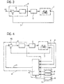
- FIG. 2 shows, in schematic terms, at the level of the general system architecture, the arrangement of connections between the various elements described above, and the control device 4 which receives the signals generated by the sensors 5 to 7 (also defined below as the first, second and third signals) and which acts on the gearbox 2 in order to change the transmission ratio of the gearbox 2 in dependence on the processing operation described further below.
- the control device 4 which receives the signals generated by the sensors 5 to 7 (also defined below as the first, second and third signals) and which acts on the gearbox 2 in order to change the transmission ratio of the gearbox 2 in dependence on the processing operation described further below.
- a set of sensors of this type (which can provide the three signals mentioned in digital form) is available under the trade name SRM TRAINING SYSTEM from the company Ingenieur remember Schoberer.
- the further functional blocks indicated 8 and 10 indicate that the method according to the invention allows the user to intervene in the operation of the system, in particular with regard to two basic factors, that is:
- the system according to the invention allows the following factors to be taken into account, by respective selective control interventions:
- the bicycle For a given resisting load, the bicycle enables a condition of impedance match, and hence an optimal frequency to be selected by changing the transmission ratios.
- the cyclist In practice, the cyclist is comparable to a high-efficiency motor which can produce its best output in terms of power produced within a fairly narrow band of pedalling frequencies (or cadences). By altering the ratios, the cyclist can keep his pedalling action within this band of greatest efficiency.
- the frequency is too low (below 60/75 rpm), the risk of muscle damage increases, whereas if it is too high (90/120 rpm) the cyclist starts to go into oxygen deficit.
- block 1 indicates the bicycle system as a whole.
- the operating conditions of the system are determined (with regard to the transmission ratio) by what may be defined, by the conventional terminology of automatic control theory, as an "actuator” (constituted, in the specific example, by the gearbox 2).
- the control system shown schematically in the form of the device 4, can therefore act on the actuator 2 (in dependence on the signals of the sensors, as shown best in the diagram of Figure 4 which will be referred to below) so as to implement a feedback operation directed towards minimizing the deviation or error "e" which may be found between a theoretical reference frequency CR and the actual frequency determined from the corresponding signal generated by the sensor 7.
- the actuator 2 In practice, when the error signal (e) is above a predetermined, possibly variable, threshold, this causes the actuator 2 to be driven in a manner such as to change the transmission ratio so as to bring the signal (e) back below the predetermined threshold.
- the transmission ratio (understood as the ratio between output speed and input speed) is reduced when the pedalling frequency tends to fall (for example, because the cyclist is pedalling uphill or against the wind) and is increased when the frequency tends to rise (for example, because the cyclist is pedalling downhill or with a favourable wind).
- the method according to the invention may be implemented either with the use of the specific criteria described further below with reference to Figure 5 and the following Figures (basically with the use of a so-called expert system, preferably of the "fuzzy" type) or, in less preferred embodiments, by adopting systems which perform the control operation (action on the gearbox/actuator 2 so as to minimize the deviation between the reference frequency CR and the actual pedalling frequency) with the use of mechanisms of different types for processing the signals, for example, of the type described in the various documents cited in the introductory part of the present description.
- the important element of the invention is that, instead of providing for operation on the basis of a reference frequency value CR which is fixed or predetermined (possibly selectively) the system according to the invention determines the reference frequency value CR (in accordance with a substantially adaptive criterion, preferably implemented in real time or substantially in real time) by deriving the reference frequency from the very parameters (pedalling effort, forward speed, actual pedalling frequency, etc.) which characterize the interaction between the cyclist and the bicycle at the time in question. All of this takes place in accordance with intervention criteria which can be determined and controlled selectively by the user.
- a substantially adaptive criterion preferably implemented in real time or substantially in real time
- the reference frequency CR is not static and determinable a priori , even selectively. In fact it depends, on the one hand, upon the resisting load (which in turn depends on various factors) and, on the other hand, on further external factors.
- the dependence of the reference frequency CR on the resisting load may be expressed as a dependence on factors such as:
- the control device 4 preferably comprises a so-called expert system operating in accordance with a fuzzy logic.
- the fuzzy logic and the respective operating mechanisms are known per se, as are the advantages which this type of logic brings to complex problems the solution of which is based more on empirical considerations resulting from experiment and simulation than on mathematical modelling of the problem.
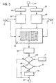
- the flow chart of Figure 5 shows a sequence of steps, between an initial step 100 and a final step 101, which is intended to be repeated by the control device 4 in order to perform an automatic control of the actuator constituted by the gearbox 2 and hence of the transmission ratio of the bicycle.
- the reference to automatic operation does not, however, mean that a bicycle 1 equipped with the system according to the invention should necessarily provide only for automatic operation.
- the cyclist can in fact exclude the operation of the system so as to be able to act on the transmission unit or transmission units manually in conventional manner (it is pointed out once more that the method according to the invention may be applied only to one or to both of the derailers normally provided on a sports cycle) or to provide for some form of semi-automatic operation.
- these methods of operation and of complete or partial deactivation of the system are such as not to require detailed description herein.
- the sequence of steps between steps 100 and 101 can be implemented with a periodic cadence and/or at a certain frequency which may be fixed or variable according to need, in dependence on specific requirements of use.
- the frequency of repetition of the steps described below does not need to be very high since, even in transitory racing stages, changes in the bicycle system 1 develop fairly slowly over time when compared with the processing speed of conventional electronic apparatus.
- the above-mentioned control sequence may be repeated, for example, at intervals of about 1 second.
- the action on the gearbox 2 in order to change the transmission ratio preferably provides for a certain low-pass filtering effect. This is to prevent instantaneous variations of one or more of the parameters used by the expert system 41 being translated into an undesired immediate change of the transmission ratio: for example, there might be a sudden change in the pedalling effort due to the fact that the cyclist has risen from the saddle upon starting to pedal, so to speak "standing" on the pedals; above all, the above-mentioned change may have a different sign in dependence on the instantaneous angular position of the pedal crank at the moment at which the cyclist starts to pedal standing up. Moreover, it seems advantageous, in any case, to prevent changes in transmission ratio, possibly with opposite signs, taking place in rapid succession.
- the expert system 41 may take account of the signal corresponding to the actual pedalling frequency in at least two different ways, that is:
- the expert system 41 operating in accordance with a fuzzy logic, converts the values of the input variables (for example, the signals read from the sensors 5, 6 and - possibly - 7) into a linguistic description in order then to work out a control strategy contained in a set of logic rules. The result is then converted back into a precise and unambiguous output datum.
- the input variables for example, the signals read from the sensors 5, 6 and - possibly - 7.
- the steps indicated 102 and 103 indicate the initial steps in which the system reads the signals coming from the sensor 5 (pedalling effort) and the sensor 6 (speed), respectively. These are preferably signals already converted into digital form beforehand at the outputs of the respective sensors, as is the case in the SRM sensors already mentioned above. If this is not the case, the conversion is performed, in known manner, in the device 4.
- the expert system converts each of the two variables read as inputs into fuzzy values, that is, linguistic values such as "high”, medium”, “low”, medium-high”, etc.
- fuzzy values that is, linguistic values such as "high”, medium”, “low”, medium-high”, etc.
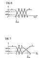
- affinity functions predefined functions which reflect the degree of affinity of the fuzzy variables to the various fuzzy values
- the affinity function relating to torque preferably has a curve of the type shown in Figure 7 in which the abscissa scale corresponds to the value of the pedalling torque (pedalling effort or force - sensor 5) expressed in N ⁇ m.
- the logic of the attribution of linguistic values to the data corresponding to the signals coming from the sensors 5 and 6 may in fact vary in dependence on various parameters set selectively on the interface modules 8, 9, 10.
- the cyclist's level of athletic preparation may mean that a speed or a pedalling effort which is to be considered high for an amateur or recreational cyclist may be considered differently (for example, medium-high, medium or even low) for a professional cyclist.
- a speed and/or pedalling effort value considered high during a translocation stage, even within a cycling race, may be considered low or even very low with reference to a sprint or a timed race.
- the intervention may, for example, be that of intervening in the operation to define the above-described affinity functions by removing or adding affinity functions; an amateur or recreational cyclist will usually be less interested in a very sophisticated and differentiated definition of the above-mentioned functions than a professional for whom the need continuously to achieve a close adaptation of the bicycle system to his physical performance may be very pressing and decisive.
- the box indicated 106 represents schematically the set of functions of the expert system dedicated to the definition of the reference frequency as a result of the attribution of the affinity functions performed in steps 104 and 105.
- the criterion for the application of the above-mentioned rules may be regarded as a type of scanning of a matrix table, for example, a two-dimensional table of which the lines are identified by the affinity functions relating to the speed and the columns are identified by the affinity functions relating to the pedalling effort.
- a matrix table for example, a two-dimensional table of which the lines are identified by the affinity functions relating to the speed and the columns are identified by the affinity functions relating to the pedalling effort.
- there may be 5x4 20, or more corresponding rules.
- the corresponding affinity functions identify the third dimension of the matrix structure (which in any case is implemented with fuzzy logic and hence with respective boxes identified by probability functions).
- the system may also conclude that, in certain conditions, the value "medium” should be attributed to the reference frequency CR at 25% and "low” at 90% .
- each fuzzy value is independent of the others so that it is wholly legitimate for the system to reach the conclusions set out above, that is, with a sum of the fuzzy values other than 100%.
- the set of functions indicated schematically by the block 106 may be rendered variable in dependence on the parameters set by the user by acting on the interface 11: this applies in particular with regard to the possibility of modifying the rules which determine the attribution of the reference frequency value in dependence on the affinity functions corresponding to the input parameters so as to be able to implement different sets of rules.
- the expert system 41 it is also possible to provide - in accordance with known criteria - for the expert system 41 to be able to store the above-mentioned set of rules or possibly several sets of rules to be used in different conditions, in dependence on learning cycles, that is, to provide for a stage for the training of the system in which the cyclist acts on the transmission, changing the ratios by means of a positive action by the cyclist (an expression of his will) in dependence on various riding conditions whilst the system learns the respective rules, subsequently applying them automatically when this operating criterion is subsequently selected.
- control mechanism and, in particular, the learning mechanism may be implemented with the use of the configurations currently known as neural or neurone networks which, as is well known, can be applied well to the implementation (and to the learning) of operating data and conditions which are purely phenomenological and cannot be expressed directly in the form of a mathematical model, particularly of an algorithmic type.
- the expert system 41 implements a reverse conversion mechanism known as "defuzzyfication" in which the fuzzy values of the output variable are combined to produce a precise value of the reference frequency parameter CR.
- step 108 the reference frequency value thus obtained is compared (as also shown more specifically at the node 42 which is actually included in the expert system 41) with the pedalling frequency value derived by the sensor 7.
- the system goes on to a further step 109 and then to yet another subsequent step 110, in which the action on the gearbox 2 is actually implemented so as to bring about the change in ratio (an increase or a decrease) in dependence on the adaptation requirements found, that is, in dependence on the sign of the deviation value "e".
- the step indicated 109 corresponds to a time check (in practice a filtering mechanism) in which the device 4 ascertains that an adequate period of time has elapsed since the preceding change in ratio. If a period of time less than a predetermined time threshold has elapsed (negative result of the comparison step 109) the system goes directly to the final step 101 without acting on the gearbox 2, postponing any ratio changing operation to a subsequent control sequence.
- step 110 changing the transmission ratio.
- step 109 it has been explained that by acting on the interface 11 and, in particular, on the module 10 (relating to the changing of the operating rules of the system) the cyclist can selectively vary the value of the time threshold used to perform the filtering function.
Landscapes
- Engineering & Computer Science (AREA)
- Chemical & Material Sciences (AREA)
- Combustion & Propulsion (AREA)
- Transportation (AREA)
- Mechanical Engineering (AREA)
- Control Of Transmission Device (AREA)
- Transmitters (AREA)
- Radio Transmission System (AREA)
- Feedback Control In General (AREA)
- Traffic Control Systems (AREA)
- Channel Selection Circuits, Automatic Tuning Circuits (AREA)
- Gear-Shifting Mechanisms (AREA)
- Communication Control (AREA)
Priority Applications (1)
| Application Number | Priority Date | Filing Date | Title |
|---|---|---|---|
| SI200030354T SI1212236T1 (en) | 1999-08-24 | 2000-08-21 | A system and a method for the control of variable-ratio transmissions |
Applications Claiming Priority (3)
| Application Number | Priority Date | Filing Date | Title |
|---|---|---|---|
| ITTO990722 | 1999-08-24 | ||
| IT1999TO000722A IT1310144B1 (it) | 1999-08-24 | 1999-08-24 | Sistema e procedimento per il controllo di trasmissioni a rapportovariabile |
| PCT/EP2000/008125 WO2001014203A1 (en) | 1999-08-24 | 2000-08-21 | A system and a method for the control of variable-ratio transmissions |
Publications (2)
| Publication Number | Publication Date |
|---|---|
| EP1212236A1 EP1212236A1 (en) | 2002-06-12 |
| EP1212236B1 true EP1212236B1 (en) | 2004-02-04 |
Family
ID=11418033
Family Applications (1)
| Application Number | Title | Priority Date | Filing Date |
|---|---|---|---|
| EP00958477A Expired - Lifetime EP1212236B1 (en) | 1999-08-24 | 2000-08-21 | A system and a method for the control of variable-ratio transmissions |
Country Status (15)
| Country | Link |
|---|---|
| US (1) | US6714849B1 (enExample) |
| EP (1) | EP1212236B1 (enExample) |
| JP (1) | JP2003507261A (enExample) |
| CN (1) | CN1165450C (enExample) |
| AT (1) | ATE258868T1 (enExample) |
| AU (1) | AU6997700A (enExample) |
| CA (1) | CA2382424C (enExample) |
| DE (1) | DE60008123T2 (enExample) |
| DK (1) | DK1212236T3 (enExample) |
| EA (1) | EA004382B1 (enExample) |
| ES (1) | ES2213039T3 (enExample) |
| HK (1) | HK1047267B (enExample) |
| IT (1) | IT1310144B1 (enExample) |
| PT (1) | PT1212236E (enExample) |
| WO (1) | WO2001014203A1 (enExample) |
Cited By (1)
| Publication number | Priority date | Publication date | Assignee | Title |
|---|---|---|---|---|
| WO2012125165A1 (en) * | 2011-03-16 | 2012-09-20 | Sram, Llc | Bicycle motor drive hub and motor controller |
Families Citing this family (30)
| Publication number | Priority date | Publication date | Assignee | Title |
|---|---|---|---|---|
| JP3522226B2 (ja) * | 2001-03-07 | 2004-04-26 | 株式会社シマノ | 自転車用変速制御装置 |
| ATE521530T1 (de) | 2002-12-06 | 2011-09-15 | Campagnolo Srl | Elektronisch, servobetätigte fahrradgangschaltung und zugehöriges verfahren |
| US20060063624A1 (en) * | 2004-09-20 | 2006-03-23 | Darrell Voss | Transmission systems and methods |
| US7522033B2 (en) * | 2005-07-27 | 2009-04-21 | Shimano, Inc. | Signal generating apparatus for a bicycle control device |
| EP1963713B1 (en) | 2005-12-09 | 2015-02-25 | Fallbrook Intellectual Property Company LLC | Continuously variable transmission |
| EP1811202A1 (en) | 2005-12-30 | 2007-07-25 | Fallbrook Technologies, Inc. | A continuously variable gear transmission |
| CN101861482B (zh) | 2007-11-16 | 2014-05-07 | 福博科知识产权有限责任公司 | 用于变速传动装置的控制器 |
| CA2708634C (en) * | 2007-12-21 | 2017-08-01 | Fallbrook Technologies Inc. | Automatic transmissions and methods therefor |
| AT507482B1 (de) * | 2008-03-21 | 2010-08-15 | Nagel Edmund | Getriebe mit stufenlos veränderbarer übersetzung zwischen einer eingangswelle und einer ausgangswelle |
| WO2012068265A1 (en) * | 2010-11-18 | 2012-05-24 | Sean Michael Simpson | System and method for controlling a transmission of a human-powered vehicle |
| WO2012086460A1 (ja) | 2010-12-22 | 2012-06-28 | マイクロスペース株式会社 | モータ駆動制御装置 |
| CN107253507B (zh) * | 2010-12-22 | 2020-06-23 | 微空间株式会社 | 电动机驱动控制装置 |
| DE102011005463A1 (de) * | 2011-03-11 | 2012-09-13 | Robert Bosch Gmbh | Verfahren zum Betreiben eines Systems, bei dem eine Stellgröße eines Stellglieds gesteuert werden kann |
| US10017225B2 (en) | 2014-10-08 | 2018-07-10 | Shimano Inc. | Bicycle transmission control device |
| US9234580B1 (en) * | 2015-05-28 | 2016-01-12 | Shimano Inc. | Control device for an automatic transmission of a bicycle |
| US10216523B2 (en) | 2015-07-17 | 2019-02-26 | General Electric Company | Systems and methods for implementing control logic |
| US10047861B2 (en) | 2016-01-15 | 2018-08-14 | Fallbrook Intellectual Property Company Llc | Systems and methods for controlling rollback in continuously variable transmissions |
| US10023266B2 (en) | 2016-05-11 | 2018-07-17 | Fallbrook Intellectual Property Company Llc | Systems and methods for automatic configuration and automatic calibration of continuously variable transmissions and bicycles having continuously variable transmissions |
| US10793222B1 (en) | 2017-03-21 | 2020-10-06 | Jonathan K. Harris | Bicycle derailleur having upper and lower alignment assemblies |
| CN106896723B (zh) * | 2017-03-31 | 2019-08-13 | 浙江大学 | 一种自行车的智能自动变速控制系统 |
| CN108896090B (zh) * | 2018-06-28 | 2024-04-16 | 上海钧正网络科技有限公司 | 一种电单车踏频检测系统及其检测方法 |
| US11527980B2 (en) | 2018-07-09 | 2022-12-13 | Shimano Inc. | Electronic device and human-powered vehicle system |
| JP7193332B2 (ja) * | 2018-12-18 | 2022-12-20 | 株式会社シマノ | 電子装置および人力駆動車用システム |
| JP6989452B2 (ja) * | 2018-07-09 | 2022-01-05 | 株式会社シマノ | 作成装置、コンポーネント制御装置、作成方法、コンポーネント制御方法、およびコンピュータプログラム |
| JP7007244B2 (ja) * | 2018-07-09 | 2022-01-24 | 株式会社シマノ | 作成装置、コンポーネント制御装置、作成方法、コンポーネント制御方法、コンピュータプログラムおよび学習モデル |
| IT201800008124A1 (it) | 2018-08-20 | 2020-02-20 | Rosario Aliperti | Sistema di Cambio CVT automatico per biciclette non elettriche |
| JP7120871B2 (ja) * | 2018-10-02 | 2022-08-17 | 株式会社シマノ | 制御装置および変速システム |
| US11215268B2 (en) | 2018-11-06 | 2022-01-04 | Fallbrook Intellectual Property Company Llc | Continuously variable transmissions, synchronous shifting, twin countershafts and methods for control of same |
| US11174922B2 (en) | 2019-02-26 | 2021-11-16 | Fallbrook Intellectual Property Company Llc | Reversible variable drives and systems and methods for control in forward and reverse directions |
| JP7457458B2 (ja) | 2019-02-27 | 2024-03-28 | 株式会社シマノ | 出力装置、コンピュータプログラム、および記憶媒体 |
Family Cites Families (17)
| Publication number | Priority date | Publication date | Assignee | Title |
|---|---|---|---|---|
| JPS57198185A (en) * | 1981-05-29 | 1982-12-04 | Sanyo Electric Co | Motor transmission for bicycle |
| US5059158A (en) | 1990-05-08 | 1991-10-22 | E.B.T., Inc. | Electronic transmission control system for a bicycle |
| IT1252262B (it) | 1991-11-18 | 1995-06-08 | Catene Calibrate Regina | Cambio automatizzato per bicicletta |
| US5213548A (en) * | 1992-03-02 | 1993-05-25 | Colbert Ralph G | Gear shifting system for derailleur equipped bicycle |
| US5261858A (en) * | 1992-06-19 | 1993-11-16 | Browning Automatic Transmission | Method and system for computer-controlled bicycle gear shifting |
| JPH0826170A (ja) * | 1994-07-13 | 1996-01-30 | Akebono Brake Ind Co Ltd | 自動変速装置付自転車 |
| US5599244A (en) | 1995-08-14 | 1997-02-04 | Ethington; Russell A. | Automatic transmission shifter for velocipedes |
| JP2988659B2 (ja) * | 1996-09-04 | 1999-12-13 | 株式会社シマノ | 自転車の擬似クランク回転数演算装置 |
| JP3284060B2 (ja) * | 1996-09-20 | 2002-05-20 | 株式会社シマノ | 自転車の変速制御方法及びその変速制御装置 |
| DE19642605A1 (de) * | 1996-10-16 | 1998-04-23 | Frank Bergler | Fahrrad-Gangschaltung |
| JPH10194185A (ja) * | 1997-01-13 | 1998-07-28 | Yamaha Motor Co Ltd | 電動自転車 |
| US6047230A (en) * | 1997-02-27 | 2000-04-04 | Spencer; Marc D. | Automatic bicycle transmission |
| US6192300B1 (en) * | 1997-06-27 | 2001-02-20 | Echowell Electronic Ltd. | Bicycle computer |
| DE19741709A1 (de) * | 1997-09-22 | 1999-03-25 | Wiehr Juergen Dipl Finanzw | Eine Fahrrad-Gangschaltung, bei der nicht der Gang, sondern die Trittfrequenz pro Minute gezählt wird |
| JP3832688B2 (ja) * | 1997-11-14 | 2006-10-11 | 本田技研工業株式会社 | 自動変速制御装置およびこれを用いた電動補助自転車 |
| US5922035A (en) * | 1997-12-03 | 1999-07-13 | Winston Hsu | Fuzzy logic control system for electrical aided vehicle |
| US6459222B1 (en) * | 1999-11-29 | 2002-10-01 | Chung Shan Institute Of Science And Technology | Bicycle control system for controlling an elebike |
-
1999
- 1999-08-24 IT IT1999TO000722A patent/IT1310144B1/it active
-
2000
- 2000-08-21 CA CA002382424A patent/CA2382424C/en not_active Expired - Fee Related
- 2000-08-21 DE DE60008123T patent/DE60008123T2/de not_active Expired - Lifetime
- 2000-08-21 WO PCT/EP2000/008125 patent/WO2001014203A1/en not_active Ceased
- 2000-08-21 JP JP2001518312A patent/JP2003507261A/ja active Pending
- 2000-08-21 DK DK00958477T patent/DK1212236T3/da active
- 2000-08-21 HK HK02108941.1A patent/HK1047267B/en not_active IP Right Cessation
- 2000-08-21 ES ES00958477T patent/ES2213039T3/es not_active Expired - Lifetime
- 2000-08-21 EP EP00958477A patent/EP1212236B1/en not_active Expired - Lifetime
- 2000-08-21 AT AT00958477T patent/ATE258868T1/de active
- 2000-08-21 US US10/069,046 patent/US6714849B1/en not_active Expired - Fee Related
- 2000-08-21 EA EA200200276A patent/EA004382B1/ru not_active IP Right Cessation
- 2000-08-21 PT PT00958477T patent/PT1212236E/pt unknown
- 2000-08-21 AU AU69977/00A patent/AU6997700A/en not_active Abandoned
- 2000-08-21 CN CNB008143943A patent/CN1165450C/zh not_active Expired - Fee Related
Cited By (1)
| Publication number | Priority date | Publication date | Assignee | Title |
|---|---|---|---|---|
| WO2012125165A1 (en) * | 2011-03-16 | 2012-09-20 | Sram, Llc | Bicycle motor drive hub and motor controller |
Also Published As
| Publication number | Publication date |
|---|---|
| ATE258868T1 (de) | 2004-02-15 |
| EP1212236A1 (en) | 2002-06-12 |
| US6714849B1 (en) | 2004-03-30 |
| DE60008123D1 (de) | 2004-03-11 |
| EA200200276A1 (ru) | 2002-08-29 |
| HK1047267B (en) | 2004-07-09 |
| CA2382424C (en) | 2008-08-19 |
| IT1310144B1 (it) | 2002-02-11 |
| CA2382424A1 (en) | 2001-03-01 |
| CN1379721A (zh) | 2002-11-13 |
| CN1165450C (zh) | 2004-09-08 |
| WO2001014203A1 (en) | 2001-03-01 |
| ITTO990722A1 (it) | 2001-02-24 |
| DE60008123T2 (de) | 2004-07-15 |
| PT1212236E (pt) | 2004-05-31 |
| DK1212236T3 (da) | 2004-04-13 |
| JP2003507261A (ja) | 2003-02-25 |
| HK1047267A1 (en) | 2003-02-14 |
| EA004382B1 (ru) | 2004-04-29 |
| AU6997700A (en) | 2001-03-19 |
| ES2213039T3 (es) | 2004-08-16 |
Similar Documents
| Publication | Publication Date | Title |
|---|---|---|
| EP1212236B1 (en) | A system and a method for the control of variable-ratio transmissions | |
| US10507885B2 (en) | Bicycle system and automatic control system thereof | |
| EP0590674B1 (en) | Method for powering a muscle-operated vehicle and vehicle | |
| US6047230A (en) | Automatic bicycle transmission | |
| AU2009100700A4 (en) | Improvements to power assisted vehicles | |
| US20240300615A1 (en) | Method for Controlling an Electric Drive Motor of an Electrically Drivable Bicycle | |
| CN106896723B (zh) | 一种自行车的智能自动变速控制系统 | |
| EP4186778B1 (en) | Auxiliary force control system and method for power-assisted bicycle | |
| CN105083464B (zh) | 自行车用电动构成部件 | |
| CN115432103B (zh) | 自行车控制系统 | |
| EP3291893A1 (en) | Improvements in or relating to exercise equipment | |
| US20210122444A1 (en) | Power assisted electric bicycle, transmission device and control method | |
| CN109153427A (zh) | 用于对于电动自行车的电动机进行控制的控制方法和设备 | |
| EP1400440A2 (en) | Shift control apparatus for bicycle transmission | |
| CN113147410B (zh) | 一种小型电动交通工具的e-abs控制方法 | |
| JPH10194185A (ja) | 電動自転車 | |
| US20240262456A1 (en) | Method for Operating a Drive System of an Electric Bike | |
| JP7660576B2 (ja) | ペダル式車両の駆動機構を制御するための方法及び装置 | |
| DE102021212668A1 (de) | Verfahren zur Ansteuerung eines Elektromotors als Antriebsmotor eines Elektrofahrrads, Computerprogramm, Steuergerät, Antriebseinheit und Elektrofahrrad | |
| US20250368285A1 (en) | System for predicting travel of human-powered vehicle and system for generating model for predicting travel of human-powered vehicle | |
| DE102024200146A1 (de) | Verfahren zum Betreiben eines Fahrradsystems und Fahrradsystem | |
| EP4410651A1 (en) | Method for adapting a power assistance provided by a drive motor of an electrically driveable or driven bicycle, method for providing pre-trained evaluation algorithms, assistance system for a bicycle and bicycle having such an assistance system | |
| DE102024200145A1 (de) | Verfahren zum Betreiben eines Fahrradsystems und Fahrradsystem | |
| DE102024200148A1 (de) | Verfahren zum Betreiben eines Fahrradsystems und Fahrradsystem | |
| CN114056479B (zh) | 一种自适应电助力单车扭矩控制方法及控制系统 |
Legal Events
| Date | Code | Title | Description |
|---|---|---|---|
| PUAI | Public reference made under article 153(3) epc to a published international application that has entered the european phase |
Free format text: ORIGINAL CODE: 0009012 |
|
| 17P | Request for examination filed |
Effective date: 20020322 |
|
| AK | Designated contracting states |
Kind code of ref document: A1 Designated state(s): AT BE CH CY DE DK ES FI FR GB GR IE IT LI LU MC NL PT SE |
|
| AX | Request for extension of the european patent |
Free format text: AL;LT PAYMENT 20020322;LV PAYMENT 20020322;MK;RO PAYMENT 20020322;SI PAYMENT 20020322 |
|
| GRAP | Despatch of communication of intention to grant a patent |
Free format text: ORIGINAL CODE: EPIDOSNIGR1 |
|
| GRAS | Grant fee paid |
Free format text: ORIGINAL CODE: EPIDOSNIGR3 |
|
| GRAA | (expected) grant |
Free format text: ORIGINAL CODE: 0009210 |
|
| AK | Designated contracting states |
Kind code of ref document: B1 Designated state(s): AT BE CH CY DE DK ES FI FR GB GR IE IT LI LU MC NL PT SE |
|
| AX | Request for extension of the european patent |
Extension state: LT LV RO SI |
|
| REG | Reference to a national code |
Ref country code: GB Ref legal event code: FG4D |
|
| REG | Reference to a national code |
Ref country code: CH Ref legal event code: EP |
|
| REG | Reference to a national code |
Ref country code: IE Ref legal event code: FG4D |
|
| REF | Corresponds to: |
Ref document number: 60008123 Country of ref document: DE Date of ref document: 20040311 Kind code of ref document: P |
|
| REG | Reference to a national code |
Ref country code: CH Ref legal event code: NV Representative=s name: JACOBACCI & PARTNERS S.P.A. |
|
| REG | Reference to a national code |
Ref country code: GR Ref legal event code: EP Ref document number: 20040400547 Country of ref document: GR |
|
| REG | Reference to a national code |
Ref country code: DK Ref legal event code: T3 Ref country code: SE Ref legal event code: TRGR |
|
| REG | Reference to a national code |
Ref country code: PT Ref legal event code: SC4A Free format text: AVAILABILITY OF NATIONAL TRANSLATION Effective date: 20040316 |
|
| REG | Reference to a national code |
Ref country code: HK Ref legal event code: GR Ref document number: 1047267 Country of ref document: HK |
|
| REG | Reference to a national code |
Ref country code: ES Ref legal event code: FG2A Ref document number: 2213039 Country of ref document: ES Kind code of ref document: T3 |
|
| ET | Fr: translation filed | ||
| PLBE | No opposition filed within time limit |
Free format text: ORIGINAL CODE: 0009261 |
|
| STAA | Information on the status of an ep patent application or granted ep patent |
Free format text: STATUS: NO OPPOSITION FILED WITHIN TIME LIMIT |
|
| REG | Reference to a national code |
Ref country code: SI Ref legal event code: IF |
|
| 26N | No opposition filed |
Effective date: 20041105 |
|
| PGFP | Annual fee paid to national office [announced via postgrant information from national office to epo] |
Ref country code: CH Payment date: 20100629 Year of fee payment: 11 Ref country code: NL Payment date: 20100813 Year of fee payment: 11 Ref country code: MC Payment date: 20100812 Year of fee payment: 11 Ref country code: IE Payment date: 20100820 Year of fee payment: 11 Ref country code: ES Payment date: 20100819 Year of fee payment: 11 |
|
| PGFP | Annual fee paid to national office [announced via postgrant information from national office to epo] |
Ref country code: FR Payment date: 20100910 Year of fee payment: 11 Ref country code: AT Payment date: 20100812 Year of fee payment: 11 Ref country code: SE Payment date: 20100826 Year of fee payment: 11 Ref country code: LU Payment date: 20100812 Year of fee payment: 11 Ref country code: IT Payment date: 20100812 Year of fee payment: 11 Ref country code: FI Payment date: 20100820 Year of fee payment: 11 Ref country code: DE Payment date: 20100823 Year of fee payment: 11 |
|
| PGFP | Annual fee paid to national office [announced via postgrant information from national office to epo] |
Ref country code: GR Payment date: 20100824 Year of fee payment: 11 Ref country code: GB Payment date: 20100819 Year of fee payment: 11 |
|
| PGFP | Annual fee paid to national office [announced via postgrant information from national office to epo] |
Ref country code: PT Payment date: 20100816 Year of fee payment: 11 Ref country code: DK Payment date: 20100810 Year of fee payment: 11 |
|
| PGFP | Annual fee paid to national office [announced via postgrant information from national office to epo] |
Ref country code: BE Payment date: 20100810 Year of fee payment: 11 Ref country code: CY Payment date: 20100804 Year of fee payment: 11 |
|
| BERE | Be: lapsed |
Owner name: *FERRERO S.P.A. Effective date: 20110831 |
|
| REG | Reference to a national code |
Ref country code: PT Ref legal event code: MM4A Free format text: LAPSE DUE TO NON-PAYMENT OF FEES Effective date: 20120221 |
|
| REG | Reference to a national code |
Ref country code: NL Ref legal event code: V1 Effective date: 20120301 |
|
| LTLA | Lt: lapse of european patent or patent extension |
Effective date: 20110821 |
|
| PG25 | Lapsed in a contracting state [announced via postgrant information from national office to epo] |
Ref country code: MC Free format text: LAPSE BECAUSE OF NON-PAYMENT OF DUE FEES Effective date: 20110831 |
|
| REG | Reference to a national code |
Ref country code: CH Ref legal event code: PL |
|
| REG | Reference to a national code |
Ref country code: SE Ref legal event code: EUG |
|
| GBPC | Gb: european patent ceased through non-payment of renewal fee |
Effective date: 20110821 |
|
| REG | Reference to a national code |
Ref country code: GR Ref legal event code: ML Ref document number: 20040400547 Country of ref document: GR Effective date: 20120302 |
|
| PG25 | Lapsed in a contracting state [announced via postgrant information from national office to epo] |
Ref country code: LI Free format text: LAPSE BECAUSE OF NON-PAYMENT OF DUE FEES Effective date: 20110831 Ref country code: CH Free format text: LAPSE BECAUSE OF NON-PAYMENT OF DUE FEES Effective date: 20110831 |
|
| REG | Reference to a national code |
Ref country code: SI Ref legal event code: KO00 Effective date: 20120326 Ref country code: DK Ref legal event code: EBP |
|
| REG | Reference to a national code |
Ref country code: FR Ref legal event code: ST Effective date: 20120430 |
|
| REG | Reference to a national code |
Ref country code: IE Ref legal event code: MM4A |
|
| PG25 | Lapsed in a contracting state [announced via postgrant information from national office to epo] |
Ref country code: IT Free format text: LAPSE BECAUSE OF NON-PAYMENT OF DUE FEES Effective date: 20110821 Ref country code: PT Free format text: LAPSE BECAUSE OF NON-PAYMENT OF DUE FEES Effective date: 20120221 Ref country code: BE Free format text: LAPSE BECAUSE OF NON-PAYMENT OF DUE FEES Effective date: 20110831 Ref country code: FI Free format text: LAPSE BECAUSE OF NON-PAYMENT OF DUE FEES Effective date: 20110821 Ref country code: NL Free format text: LAPSE BECAUSE OF NON-PAYMENT OF DUE FEES Effective date: 20120301 Ref country code: GR Free format text: LAPSE BECAUSE OF NON-PAYMENT OF DUE FEES Effective date: 20120302 |
|
| REG | Reference to a national code |
Ref country code: DE Ref legal event code: R119 Ref document number: 60008123 Country of ref document: DE Effective date: 20120301 |
|
| PG25 | Lapsed in a contracting state [announced via postgrant information from national office to epo] |
Ref country code: CY Free format text: LAPSE BECAUSE OF NON-PAYMENT OF DUE FEES Effective date: 20110821 |
|
| PG25 | Lapsed in a contracting state [announced via postgrant information from national office to epo] |
Ref country code: DK Free format text: LAPSE BECAUSE OF NON-PAYMENT OF DUE FEES Effective date: 20110831 Ref country code: IE Free format text: LAPSE BECAUSE OF NON-PAYMENT OF DUE FEES Effective date: 20110821 |
|
| PG25 | Lapsed in a contracting state [announced via postgrant information from national office to epo] |
Ref country code: FR Free format text: LAPSE BECAUSE OF NON-PAYMENT OF DUE FEES Effective date: 20110831 Ref country code: GB Free format text: LAPSE BECAUSE OF NON-PAYMENT OF DUE FEES Effective date: 20110821 |
|
| REG | Reference to a national code |
Ref country code: ES Ref legal event code: FD2A Effective date: 20121207 |
|
| REG | Reference to a national code |
Ref country code: AT Ref legal event code: MM01 Ref document number: 258868 Country of ref document: AT Kind code of ref document: T Effective date: 20110821 |
|
| PG25 | Lapsed in a contracting state [announced via postgrant information from national office to epo] |
Ref country code: AT Free format text: LAPSE BECAUSE OF NON-PAYMENT OF DUE FEES Effective date: 20110821 |
|
| PG25 | Lapsed in a contracting state [announced via postgrant information from national office to epo] |
Ref country code: ES Free format text: LAPSE BECAUSE OF NON-PAYMENT OF DUE FEES Effective date: 20110822 |
|
| PG25 | Lapsed in a contracting state [announced via postgrant information from national office to epo] |
Ref country code: SE Free format text: LAPSE BECAUSE OF NON-PAYMENT OF DUE FEES Effective date: 20110822 |
|
| PG25 | Lapsed in a contracting state [announced via postgrant information from national office to epo] |
Ref country code: LU Free format text: LAPSE BECAUSE OF NON-PAYMENT OF DUE FEES Effective date: 20110821 |
|
| PG25 | Lapsed in a contracting state [announced via postgrant information from national office to epo] |
Ref country code: DE Free format text: LAPSE BECAUSE OF NON-PAYMENT OF DUE FEES Effective date: 20120301 |