EP1212236B1 - A system and a method for the control of variable-ratio transmissions - Google Patents
A system and a method for the control of variable-ratio transmissions Download PDFInfo
- Publication number
- EP1212236B1 EP1212236B1 EP00958477A EP00958477A EP1212236B1 EP 1212236 B1 EP1212236 B1 EP 1212236B1 EP 00958477 A EP00958477 A EP 00958477A EP 00958477 A EP00958477 A EP 00958477A EP 1212236 B1 EP1212236 B1 EP 1212236B1
- Authority
- EP
- European Patent Office
- Prior art keywords
- signal
- affinity
- dependence
- actuator
- frequency
- Prior art date
- Legal status (The legal status is an assumption and is not a legal conclusion. Google has not performed a legal analysis and makes no representation as to the accuracy of the status listed.)
- Expired - Lifetime
Links
Images

Classifications
-
- B—PERFORMING OPERATIONS; TRANSPORTING
- B62—LAND VEHICLES FOR TRAVELLING OTHERWISE THAN ON RAILS
- B62M—RIDER PROPULSION OF WHEELED VEHICLES OR SLEDGES; POWERED PROPULSION OF SLEDGES OR SINGLE-TRACK CYCLES; TRANSMISSIONS SPECIALLY ADAPTED FOR SUCH VEHICLES
- B62M25/00—Actuators for gearing speed-change mechanisms specially adapted for cycles
- B62M25/08—Actuators for gearing speed-change mechanisms specially adapted for cycles with electrical or fluid transmitting systems
Definitions
- the present invention addresses the problem of the control of variable-ratio transmissions.
- a typical example of a transmission of this type which will be referred to for simplicity in the following description, is that of a bicycle transmissions.
- a method and a device for automatically controlling the transmission ratio of a bicycle so as automatically to identify the optimal ratio in dependence on the pedalling effort or force are known from EP-A-0 831 021 which is taken as the model for the preambles to Claims 1 and 10.
- the object of the present invention is to improve systems for controlling the ratio in variable-ratio transmissions, particularly with regard to the optimization of the interaction between an apparatus having such a transmission and an operator using the apparatus.
- the application of the invention is particularly advantageous in the cycling field and, in particular, in the field of competitive cycling.
- apparatus having a variable-ratio transmission is generally indicated 1.
- the apparatus in question is constituted by a bicycle such as, for example, a sports cycle.
- the bicycle 1 is equipped with the following devices:
- the sensor 7 which detects the pedalling frequency can advantageously be combined with the sensor 5 which detects the pedalling effort.
- gearbox 2 which can advantageously be used in the context of the invention is constituted by the gearbox sold under the reference ZMS 800 by the company MAVIC.
- FIG. 2 shows, in schematic terms, at the level of the general system architecture, the arrangement of connections between the various elements described above, and the control device 4 which receives the signals generated by the sensors 5 to 7 (also defined below as the first, second and third signals) and which acts on the gearbox 2 in order to change the transmission ratio of the gearbox 2 in dependence on the processing operation described further below.
- the control device 4 which receives the signals generated by the sensors 5 to 7 (also defined below as the first, second and third signals) and which acts on the gearbox 2 in order to change the transmission ratio of the gearbox 2 in dependence on the processing operation described further below.
- a set of sensors of this type (which can provide the three signals mentioned in digital form) is available under the trade name SRM TRAINING SYSTEM from the company Ingenieur remember Schoberer.
- the further functional blocks indicated 8 and 10 indicate that the method according to the invention allows the user to intervene in the operation of the system, in particular with regard to two basic factors, that is:
- the system according to the invention allows the following factors to be taken into account, by respective selective control interventions:
- the bicycle For a given resisting load, the bicycle enables a condition of impedance match, and hence an optimal frequency to be selected by changing the transmission ratios.
- the cyclist In practice, the cyclist is comparable to a high-efficiency motor which can produce its best output in terms of power produced within a fairly narrow band of pedalling frequencies (or cadences). By altering the ratios, the cyclist can keep his pedalling action within this band of greatest efficiency.
- the frequency is too low (below 60/75 rpm), the risk of muscle damage increases, whereas if it is too high (90/120 rpm) the cyclist starts to go into oxygen deficit.
- block 1 indicates the bicycle system as a whole.
- the operating conditions of the system are determined (with regard to the transmission ratio) by what may be defined, by the conventional terminology of automatic control theory, as an "actuator” (constituted, in the specific example, by the gearbox 2).
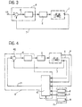
- the control system shown schematically in the form of the device 4, can therefore act on the actuator 2 (in dependence on the signals of the sensors, as shown best in the diagram of Figure 4 which will be referred to below) so as to implement a feedback operation directed towards minimizing the deviation or error "e" which may be found between a theoretical reference frequency CR and the actual frequency determined from the corresponding signal generated by the sensor 7.
- the actuator 2 In practice, when the error signal (e) is above a predetermined, possibly variable, threshold, this causes the actuator 2 to be driven in a manner such as to change the transmission ratio so as to bring the signal (e) back below the predetermined threshold.
- the transmission ratio (understood as the ratio between output speed and input speed) is reduced when the pedalling frequency tends to fall (for example, because the cyclist is pedalling uphill or against the wind) and is increased when the frequency tends to rise (for example, because the cyclist is pedalling downhill or with a favourable wind).
- the method according to the invention may be implemented either with the use of the specific criteria described further below with reference to Figure 5 and the following Figures (basically with the use of a so-called expert system, preferably of the "fuzzy" type) or, in less preferred embodiments, by adopting systems which perform the control operation (action on the gearbox/actuator 2 so as to minimize the deviation between the reference frequency CR and the actual pedalling frequency) with the use of mechanisms of different types for processing the signals, for example, of the type described in the various documents cited in the introductory part of the present description.
- the important element of the invention is that, instead of providing for operation on the basis of a reference frequency value CR which is fixed or predetermined (possibly selectively) the system according to the invention determines the reference frequency value CR (in accordance with a substantially adaptive criterion, preferably implemented in real time or substantially in real time) by deriving the reference frequency from the very parameters (pedalling effort, forward speed, actual pedalling frequency, etc.) which characterize the interaction between the cyclist and the bicycle at the time in question. All of this takes place in accordance with intervention criteria which can be determined and controlled selectively by the user.
- a substantially adaptive criterion preferably implemented in real time or substantially in real time
- the reference frequency CR is not static and determinable a priori , even selectively. In fact it depends, on the one hand, upon the resisting load (which in turn depends on various factors) and, on the other hand, on further external factors.
- the dependence of the reference frequency CR on the resisting load may be expressed as a dependence on factors such as:
- the control device 4 preferably comprises a so-called expert system operating in accordance with a fuzzy logic.
- the fuzzy logic and the respective operating mechanisms are known per se, as are the advantages which this type of logic brings to complex problems the solution of which is based more on empirical considerations resulting from experiment and simulation than on mathematical modelling of the problem.
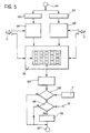
- the flow chart of Figure 5 shows a sequence of steps, between an initial step 100 and a final step 101, which is intended to be repeated by the control device 4 in order to perform an automatic control of the actuator constituted by the gearbox 2 and hence of the transmission ratio of the bicycle.
- the reference to automatic operation does not, however, mean that a bicycle 1 equipped with the system according to the invention should necessarily provide only for automatic operation.
- the cyclist can in fact exclude the operation of the system so as to be able to act on the transmission unit or transmission units manually in conventional manner (it is pointed out once more that the method according to the invention may be applied only to one or to both of the derailers normally provided on a sports cycle) or to provide for some form of semi-automatic operation.
- these methods of operation and of complete or partial deactivation of the system are such as not to require detailed description herein.
- the sequence of steps between steps 100 and 101 can be implemented with a periodic cadence and/or at a certain frequency which may be fixed or variable according to need, in dependence on specific requirements of use.
- the frequency of repetition of the steps described below does not need to be very high since, even in transitory racing stages, changes in the bicycle system 1 develop fairly slowly over time when compared with the processing speed of conventional electronic apparatus.
- the above-mentioned control sequence may be repeated, for example, at intervals of about 1 second.
- the action on the gearbox 2 in order to change the transmission ratio preferably provides for a certain low-pass filtering effect. This is to prevent instantaneous variations of one or more of the parameters used by the expert system 41 being translated into an undesired immediate change of the transmission ratio: for example, there might be a sudden change in the pedalling effort due to the fact that the cyclist has risen from the saddle upon starting to pedal, so to speak "standing" on the pedals; above all, the above-mentioned change may have a different sign in dependence on the instantaneous angular position of the pedal crank at the moment at which the cyclist starts to pedal standing up. Moreover, it seems advantageous, in any case, to prevent changes in transmission ratio, possibly with opposite signs, taking place in rapid succession.
- the expert system 41 may take account of the signal corresponding to the actual pedalling frequency in at least two different ways, that is:
- the expert system 41 operating in accordance with a fuzzy logic, converts the values of the input variables (for example, the signals read from the sensors 5, 6 and - possibly - 7) into a linguistic description in order then to work out a control strategy contained in a set of logic rules. The result is then converted back into a precise and unambiguous output datum.
- the input variables for example, the signals read from the sensors 5, 6 and - possibly - 7.
- the steps indicated 102 and 103 indicate the initial steps in which the system reads the signals coming from the sensor 5 (pedalling effort) and the sensor 6 (speed), respectively. These are preferably signals already converted into digital form beforehand at the outputs of the respective sensors, as is the case in the SRM sensors already mentioned above. If this is not the case, the conversion is performed, in known manner, in the device 4.
- the expert system converts each of the two variables read as inputs into fuzzy values, that is, linguistic values such as "high”, medium”, “low”, medium-high”, etc.
- fuzzy values that is, linguistic values such as "high”, medium”, “low”, medium-high”, etc.
- affinity functions predefined functions which reflect the degree of affinity of the fuzzy variables to the various fuzzy values
- the affinity function relating to torque preferably has a curve of the type shown in Figure 7 in which the abscissa scale corresponds to the value of the pedalling torque (pedalling effort or force - sensor 5) expressed in N ⁇ m.
- the logic of the attribution of linguistic values to the data corresponding to the signals coming from the sensors 5 and 6 may in fact vary in dependence on various parameters set selectively on the interface modules 8, 9, 10.
- the cyclist's level of athletic preparation may mean that a speed or a pedalling effort which is to be considered high for an amateur or recreational cyclist may be considered differently (for example, medium-high, medium or even low) for a professional cyclist.
- a speed and/or pedalling effort value considered high during a translocation stage, even within a cycling race, may be considered low or even very low with reference to a sprint or a timed race.
- the intervention may, for example, be that of intervening in the operation to define the above-described affinity functions by removing or adding affinity functions; an amateur or recreational cyclist will usually be less interested in a very sophisticated and differentiated definition of the above-mentioned functions than a professional for whom the need continuously to achieve a close adaptation of the bicycle system to his physical performance may be very pressing and decisive.
- the box indicated 106 represents schematically the set of functions of the expert system dedicated to the definition of the reference frequency as a result of the attribution of the affinity functions performed in steps 104 and 105.
- the criterion for the application of the above-mentioned rules may be regarded as a type of scanning of a matrix table, for example, a two-dimensional table of which the lines are identified by the affinity functions relating to the speed and the columns are identified by the affinity functions relating to the pedalling effort.
- a matrix table for example, a two-dimensional table of which the lines are identified by the affinity functions relating to the speed and the columns are identified by the affinity functions relating to the pedalling effort.
- there may be 5x4 20, or more corresponding rules.
- the corresponding affinity functions identify the third dimension of the matrix structure (which in any case is implemented with fuzzy logic and hence with respective boxes identified by probability functions).
- the system may also conclude that, in certain conditions, the value "medium” should be attributed to the reference frequency CR at 25% and "low” at 90% .
- each fuzzy value is independent of the others so that it is wholly legitimate for the system to reach the conclusions set out above, that is, with a sum of the fuzzy values other than 100%.
- the set of functions indicated schematically by the block 106 may be rendered variable in dependence on the parameters set by the user by acting on the interface 11: this applies in particular with regard to the possibility of modifying the rules which determine the attribution of the reference frequency value in dependence on the affinity functions corresponding to the input parameters so as to be able to implement different sets of rules.
- the expert system 41 it is also possible to provide - in accordance with known criteria - for the expert system 41 to be able to store the above-mentioned set of rules or possibly several sets of rules to be used in different conditions, in dependence on learning cycles, that is, to provide for a stage for the training of the system in which the cyclist acts on the transmission, changing the ratios by means of a positive action by the cyclist (an expression of his will) in dependence on various riding conditions whilst the system learns the respective rules, subsequently applying them automatically when this operating criterion is subsequently selected.
- control mechanism and, in particular, the learning mechanism may be implemented with the use of the configurations currently known as neural or neurone networks which, as is well known, can be applied well to the implementation (and to the learning) of operating data and conditions which are purely phenomenological and cannot be expressed directly in the form of a mathematical model, particularly of an algorithmic type.
- the expert system 41 implements a reverse conversion mechanism known as "defuzzyfication" in which the fuzzy values of the output variable are combined to produce a precise value of the reference frequency parameter CR.
- step 108 the reference frequency value thus obtained is compared (as also shown more specifically at the node 42 which is actually included in the expert system 41) with the pedalling frequency value derived by the sensor 7.
- the system goes on to a further step 109 and then to yet another subsequent step 110, in which the action on the gearbox 2 is actually implemented so as to bring about the change in ratio (an increase or a decrease) in dependence on the adaptation requirements found, that is, in dependence on the sign of the deviation value "e".
- the step indicated 109 corresponds to a time check (in practice a filtering mechanism) in which the device 4 ascertains that an adequate period of time has elapsed since the preceding change in ratio. If a period of time less than a predetermined time threshold has elapsed (negative result of the comparison step 109) the system goes directly to the final step 101 without acting on the gearbox 2, postponing any ratio changing operation to a subsequent control sequence.
- step 110 changing the transmission ratio.
- step 109 it has been explained that by acting on the interface 11 and, in particular, on the module 10 (relating to the changing of the operating rules of the system) the cyclist can selectively vary the value of the time threshold used to perform the filtering function.
Abstract
Description
- The present invention addresses the problem of the control of variable-ratio transmissions.
- A typical example of a transmission of this type, which will be referred to for simplicity in the following description, is that of a bicycle transmissions. In this connection, a method and a device for automatically controlling the transmission ratio of a bicycle so as automatically to identify the optimal ratio in dependence on the pedalling effort or force are known from EP-A-0 831 021 which is taken as the model for the preambles to
Claims - The same subject is addressed in various other patent documents such as, for example, US-A-5 059 158, US-A-5 538 477, US-A-5 356 348, US-A-5 569 104 and US-A-5 728 017, in which it can be seen that the control may be exerted either on the rear derailer or on the front derailer, or on both derailers of a sports cycle.
- The object of the present invention is to improve systems for controlling the ratio in variable-ratio transmissions, particularly with regard to the optimization of the interaction between an apparatus having such a transmission and an operator using the apparatus.
- According to the present invention, this object is achieved by means of a system having the specific characteristics recited in the following claims. The invention also relates to the respective method of operation.
- The application of the invention is particularly advantageous in the cycling field and, in particular, in the field of competitive cycling.
- The invention will now be described, purely by way of nonlimiting example, with reference to the appended drawings, in which:
- Figure 1 shows schematically the application of a system according to the invention to a cycle such as a bicycle,
- Figure 2 shows the structure of a system according to the invention schematically in the form of a block diagram,
- Figures 3 and 4 show the general criteria of the operation of a system according to the invention in two successive levels of detail,
- Figure 5 shows the operation of the system according to the invention in the form of a flow chart, and
- Figures 6 and 7 are further graphs indicative of the criteria (affinity functions) for the operation of the system.
-
- In Figure 1, apparatus having a variable-ratio transmission is generally indicated 1. In the embodiment shown, the apparatus in question is constituted by a bicycle such as, for example, a sports cycle.
- As well as comprising the parts which normally make up a bicycle of this type (which parts clearly do not need to be described and recited in detail herein), the
bicycle 1 is equipped with the following devices: - an electrically-operated
gearbox 2, shown here associated with the rear derailer of the bicycle 1 (in possible variants of the invention such a gearbox could alternatively or additionally be provided on the front derailer of the bicycle, if it has one); the gearbox concerned can thus change the position in which the bicycle chain (driven by the pedal crank 3 by means of which the cyclist applies the input driving force to the transmission) cooperates in a meshed arrangement with the sprockets associated with the rear wheel hub of the bicycle, in dependence on a control signal, - a control device 4, the heart of which is preferably constituted by a microprocessor, for generating the control signal, and
- a set of
sensors 5 to 7 which are sensitive to respective parameters of use of the bicycle and can generate respective signals to be received and processed by the device 4; these are, basically, asensor 5 which can detect the pedalling force or effort exerted by the cyclist on the pedals (that is the driving force), asensor 6 which is sensitive to the forward speed of the bicycle 1 (in general terms, the frequency or speed of operation of the apparatus represented herein by the bicycle 1), as well as asensor 7 which is sensitive to the pedalling frequency, that is, the frequency of the periodic action by which the cyclist applies the input driving force by means of the pedal crank 3. - Although they are theoretically separate, the various sensors in question may in fact be combined with one another and/or with other components of the system.
- For example, the
sensor 7 which detects the pedalling frequency can advantageously be combined with thesensor 5 which detects the pedalling effort. - It should again be stated that all of the various components mentioned above can be considered known per se (as is proved by the descriptions in the prior patent documents cited in the introductory part of this description) and/or currently available commercially. For example, a
gearbox 2 which can advantageously be used in the context of the invention is constituted by the gearbox sold under the reference ZMS 800 by the company MAVIC. - The block diagram of Figure 2 shows, in schematic terms, at the level of the general system architecture, the arrangement of connections between the various elements described above, and the control device 4 which receives the signals generated by the
sensors 5 to 7 (also defined below as the first, second and third signals) and which acts on thegearbox 2 in order to change the transmission ratio of thegearbox 2 in dependence on the processing operation described further below. - A set of sensors of this type (which can provide the three signals mentioned in digital form) is available under the trade name SRM TRAINING SYSTEM from the company Ingenieurbüro Schoberer.
- The further functional blocks indicated 8 and 10 indicate that the method according to the invention allows the user to intervene in the operation of the system, in particular with regard to two basic factors, that is:
- the way in which the device 4 interprets or classifies (as
will be described further below) the values of the signals
received from the
sensors 5 to 7, and - the processing logic implemented by the device 4 with a
view to acting on the
gearbox 2. - In particular, in the currently-preferred embodiment, the system according to the invention allows the following factors to be taken into account, by respective selective control interventions:
- the cyclist's level of preparation and fitness (module 8),
- the riding or racing strategy adopted by the cyclist (module 9) and, in general,
- the rules which the user intends to be followed in the automatic management of the transmission control function (module 10).
- Before proceeding with the detailed description of a possible embodiment of the invention, it seems useful to describe briefly the basic principles upon which the invention is based. This will be done with specific reference to its possible application in the cycling field.
- It is a fact that, for given peripheral conditions (physical characteristics, athletic preparation, type of bicycle, gradient of the road and atmospheric conditions: e.g. opposing or favouring wind. etc.), the maximum power which a cyclist can transfer to the bicycle is achieved in the region of a very precise pedalling frequency which in practice is identified by the speed of rotation (revolutions per minute or rpm) imparted to the pedal crank.
- This is due to the fact that, given a certain resisting load, there is always an optimal impedance match between the resisting load and the frequency such as to maximize the power produced, that is, to maximize efficiency.
- These remarks are confirmed by numerous scientific works such as, for example:
- Gregor, R.J. and Rugg S.G. (1986), "Effects of saddle height and pedalling cadence on power output and efficiency", in E.R. Burke (Ed.), Science of cycling (pp. 69-90). Champaign, IL: Human Kinetics;
- Kyle C.R. and Caiozzo, V.J. (1986), "Experiments in human ergometry as applied to the design of human powered vehicles", International Journal of Sports Biomechanics, 2, 6-19; and
- Allan V. Abbott and David Gordon Wilson (1995), "Human-Powered Vehicles", (p. 35-37), IL: Human Kinetics.
-
- For a given resisting load, the bicycle enables a condition of impedance match, and hence an optimal frequency to be selected by changing the transmission ratios. In practice, the cyclist is comparable to a high-efficiency motor which can produce its best output in terms of power produced within a fairly narrow band of pedalling frequencies (or cadences). By altering the ratios, the cyclist can keep his pedalling action within this band of greatest efficiency. In practice, if the frequency is too low (below 60/75 rpm), the risk of muscle damage increases, whereas if it is too high (90/120 rpm) the cyclist starts to go into oxygen deficit.
- By way of direct conceptual reference (but this should not be seen as indicative of a precise analogy of the functional blocks) the criterion of maximizing the power output by arranging for the cyclist always to be able to pedal at the optimal frequency can be represented in the form of the control diagram shown in Figure 3.
- In this diagram,
block 1 indicates the bicycle system as a whole. The operating conditions of the system are determined (with regard to the transmission ratio) by what may be defined, by the conventional terminology of automatic control theory, as an "actuator" (constituted, in the specific example, by the gearbox 2). The control system, shown schematically in the form of the device 4, can therefore act on the actuator 2 (in dependence on the signals of the sensors, as shown best in the diagram of Figure 4 which will be referred to below) so as to implement a feedback operation directed towards minimizing the deviation or error "e" which may be found between a theoretical reference frequency CR and the actual frequency determined from the corresponding signal generated by thesensor 7. - In practice, when the error signal (e) is above a predetermined, possibly variable, threshold, this causes the
actuator 2 to be driven in a manner such as to change the transmission ratio so as to bring the signal (e) back below the predetermined threshold. In practice (speaking in deliberately schematic terms) the transmission ratio (understood as the ratio between output speed and input speed) is reduced when the pedalling frequency tends to fall (for example, because the cyclist is pedalling uphill or against the wind) and is increased when the frequency tends to rise (for example, because the cyclist is pedalling downhill or with a favourable wind). - From this last point of view, the method according to the invention may be implemented either with the use of the specific criteria described further below with reference to Figure 5 and the following Figures (basically with the use of a so-called expert system, preferably of the "fuzzy" type) or, in less preferred embodiments, by adopting systems which perform the control operation (action on the gearbox/
actuator 2 so as to minimize the deviation between the reference frequency CR and the actual pedalling frequency) with the use of mechanisms of different types for processing the signals, for example, of the type described in the various documents cited in the introductory part of the present description. - The important element of the invention is that, instead of providing for operation on the basis of a reference frequency value CR which is fixed or predetermined (possibly selectively) the system according to the invention determines the reference frequency value CR (in accordance with a substantially adaptive criterion, preferably implemented in real time or substantially in real time) by deriving the reference frequency from the very parameters (pedalling effort, forward speed, actual pedalling frequency, etc.) which characterize the interaction between the cyclist and the bicycle at the time in question. All of this takes place in accordance with intervention criteria which can be determined and controlled selectively by the user.
- The importance of this factor can be understood better if it is noted that the reference frequency CR is not static and determinable a priori, even selectively. In fact it depends, on the one hand, upon the resisting load (which in turn depends on various factors) and, on the other hand, on further external factors.
- For example, the dependence of the reference frequency CR on the resisting load may be expressed as a dependence on factors such as:
- the torque exerted on the pedal crank (the torque required to maintain a constant speed varies with variations of the characteristics of the track), and
- the speed (aerodynamic resistance, which is a function of the square of the speed, increases as the speed increases).
- Dependence on other factors, on the other hand, includes factors such as, for example:
- racing strategy: the cyclist may decide to pedal for a race, for a sprint, or simply for a tiring translocation, in accordance with criteria which express his will, and hence a basically predictive behaviour projected into the future and not based on parameters detected and/or detectable in the past or in the present, and
- the cyclist's level of preparation; the more the cyclist has trained and prepared, the better he will be able to sustain high frequencies, or lower frequencies but with greater effort produced.
- The control device 4 preferably comprises a so-called expert system operating in accordance with a fuzzy logic. The fuzzy logic and the respective operating mechanisms are known per se, as are the advantages which this type of logic brings to complex problems the solution of which is based more on empirical considerations resulting from experiment and simulation than on mathematical modelling of the problem.
- For general information on these subjects, for example, the reference work by Mohammad JAMSIDI, Nader VADIEE, and Timothy J. ROSS - "Fuzzy Logic And Control" (1993) - IL: Prentice Hall, may usefully be consulted.
- The flow chart of Figure 5 shows a sequence of steps, between an
initial step 100 and afinal step 101, which is intended to be repeated by the control device 4 in order to perform an automatic control of the actuator constituted by thegearbox 2 and hence of the transmission ratio of the bicycle. - The reference to automatic operation does not, however, mean that a
bicycle 1 equipped with the system according to the invention should necessarily provide only for automatic operation. As in known systems, the cyclist can in fact exclude the operation of the system so as to be able to act on the transmission unit or transmission units manually in conventional manner (it is pointed out once more that the method according to the invention may be applied only to one or to both of the derailers normally provided on a sports cycle) or to provide for some form of semi-automatic operation. In any case, these methods of operation and of complete or partial deactivation of the system are such as not to require detailed description herein. - To concentrate attention on automatic operation, it is pointed out again that the sequence of steps between
steps bicycle system 1 develop fairly slowly over time when compared with the processing speed of conventional electronic apparatus. The above-mentioned control sequence may be repeated, for example, at intervals of about 1 second. - The action on the
gearbox 2 in order to change the transmission ratio preferably provides for a certain low-pass filtering effect. This is to prevent instantaneous variations of one or more of the parameters used by theexpert system 41 being translated into an undesired immediate change of the transmission ratio: for example, there might be a sudden change in the pedalling effort due to the fact that the cyclist has risen from the saddle upon starting to pedal, so to speak "standing" on the pedals; above all, the above-mentioned change may have a different sign in dependence on the instantaneous angular position of the pedal crank at the moment at which the cyclist starts to pedal standing up. Moreover, it seems advantageous, in any case, to prevent changes in transmission ratio, possibly with opposite signs, taking place in rapid succession. - The description of the operation of the
expert system 41 will be given below, upon the assumption that the expert system receives at its input exclusively the signals corresponding to the pedalling force or effort (sensor 5) and to the speed of the bicycle (sensor 6). This selection is dictated both by reasons of simplicity of description and by the consideration that a skilled person familiar with the design and construction of expert systems will certainly have no difficulty in also including the third parameter (actual pedalling frequency) in the operation of the system. However, this latter parameter may be used by the expert system purely to perform, at the node indicated 42 in Figure 4, a comparison between this parameter and the reference frequency CR defined by the expert system on the basis of the signals coming from thesensors current gear ratio 2, if it is not available by other means. - In other words, the
expert system 41 may take account of the signal corresponding to the actual pedalling frequency in at least two different ways, that is: - on the basis of the method shown in Figure 5, by
identifying the signal corresponding to the reference
frequency CR solely on the basis of the pedalling effort
signal and of the speed signal, using the signal
corresponding to the actual pedalling frequency coming from
the
sensor 7 purely for generating the error signal (signal e) used to control thegearbox 2, and - on the basis of a variant, not shown explicitly, also using the signal relating to the actual pedalling frequency to define the reference frequency CR.
- Basically, the
expert system 41, operating in accordance with a fuzzy logic, converts the values of the input variables (for example, the signals read from thesensors - With reference to the flow chart of Figure 5, the steps indicated 102 and 103 indicate the initial steps in which the system reads the signals coming from the sensor 5 (pedalling effort) and the sensor 6 (speed), respectively. These are preferably signals already converted into digital form beforehand at the outputs of the respective sensors, as is the case in the SRM sensors already mentioned above. If this is not the case, the conversion is performed, in known manner, in the device 4.
- In the
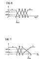
subsequent steps - The affinity function relating to speed preferably has a curve of the type shown in Figure 6 in which the abscissa scale corresponds to the speed value (sensor 6) expressed in km/h. It should be noted that there are 5 fuzzy values (linguistic values: B = low, MB = medium low, M = medium, MA = medium high, A = high).
- The affinity function relating to torque preferably has a curve of the type shown in Figure 7 in which the abscissa scale corresponds to the value of the pedalling torque (pedalling effort or force - sensor 5) expressed in N·m. There are 4 fuzzy values (B, MB, M, A).
- Again, it should be stated that the steps illustrated by
boxes 102 to 105 have been shown as theoretically performed by a parallel processing method for each input parameter since this representation is, above all, more readily understood. It will be clear to experts that the same result can be achieved by serial processes. - It will also be noted that the flow chart of Figure 5 makes clear that it is possible to intervene in
steps interface modules user interface 11 such as, for example, a keypad or an analogue control module disposed, for example, on the handlebars (Figure 1) in a position readily accessible to the cyclist. - The logic of the attribution of linguistic values to the data corresponding to the signals coming from the
sensors interface modules - For example, the cyclist's level of athletic preparation (module 8) may mean that a speed or a pedalling effort which is to be considered high for an amateur or recreational cyclist may be considered differently (for example, medium-high, medium or even low) for a professional cyclist.
- In exactly the same way, with reference to the function of the module 9, to which a role of identifying racing strategy has been attributed, clearly, a speed and/or pedalling effort value considered high during a translocation stage, even within a cycling race, may be considered low or even very low with reference to a sprint or a timed race.
- The foregoing also applies in identical manner to the
module 10 which supervises the general definition of the rules of operation of the expert system. In this case, the intervention may, for example, be that of intervening in the operation to define the above-described affinity functions by removing or adding affinity functions; an amateur or recreational cyclist will usually be less interested in a very sophisticated and differentiated definition of the above-mentioned functions than a professional for whom the need continuously to achieve a close adaptation of the bicycle system to his physical performance may be very pressing and decisive. - The box indicated 106 represents schematically the set of functions of the expert system dedicated to the definition of the reference frequency as a result of the attribution of the affinity functions performed in
steps - In a possible embodiment (which is known per se to experts in the design of these systems and therefore does not require a detailed description herein), the criterion for the application of the above-mentioned rules may be regarded as a type of scanning of a matrix table, for example, a two-dimensional table of which the lines are identified by the affinity functions relating to the speed and the columns are identified by the affinity functions relating to the pedalling effort. With reference to the examples given in Figures 6 and 7 (which provide for five and four fuzzy values, respectively), there may be 5x4=20, or more corresponding rules. If the parameter relating to the actual pedalling frequency is also present, the corresponding affinity functions identify the third dimension of the matrix structure (which in any case is implemented with fuzzy logic and hence with respective boxes identified by probability functions).
- The rules implemented in
box 106 can be written in explicit form in the following manner: - A) if the speed is LOW and the torque is HIGH THEN the reference frequency is LOW
- B) if the speed is MEDIUM LOW and the torque is HIGH THEN the reference frequency is MEDIUM LOW
- C) if the speed is LOW and the torque is MEDIUM THEN the reference frequency is MEDIUM LOW
- D) if the speed is MEDIUM LOW and the torque is MEDIUM THEN the reference frequency is MEDIUM LOW etc.
-
- In terms of the value (VALCR) of the reference frequency value CR, the output fuzzy values could be:
VALCR LOW = 68 rpm VALCR MEDIUM LOW = 78 rpm VALCR MEDIUM = 86 rpm VALCR MEDIUM HIGH = 92 rpm VALCR HIGH = 95 rpm - Naturally, as is well known to experts in the design of fuzzy systems, the system may also conclude that, in certain conditions, the value "medium" should be attributed to the reference frequency CR at 25% and "low" at 90% . As is well known to experts in fuzzy logic, each fuzzy value is independent of the others so that it is wholly legitimate for the system to reach the conclusions set out above, that is, with a sum of the fuzzy values other than 100%.
- It will also be appreciated that - in accordance with per se known criteria - the set of functions indicated schematically by the
block 106 may be rendered variable in dependence on the parameters set by the user by acting on the interface 11: this applies in particular with regard to the possibility of modifying the rules which determine the attribution of the reference frequency value in dependence on the affinity functions corresponding to the input parameters so as to be able to implement different sets of rules. - It is also possible to provide - in accordance with known criteria - for the
expert system 41 to be able to store the above-mentioned set of rules or possibly several sets of rules to be used in different conditions, in dependence on learning cycles, that is, to provide for a stage for the training of the system in which the cyclist acts on the transmission, changing the ratios by means of a positive action by the cyclist (an expression of his will) in dependence on various riding conditions whilst the system learns the respective rules, subsequently applying them automatically when this operating criterion is subsequently selected. - The above-mentioned control mechanism and, in particular, the learning mechanism, may be implemented with the use of the configurations currently known as neural or neurone networks which, as is well known, can be applied well to the implementation (and to the learning) of operating data and conditions which are purely phenomenological and cannot be expressed directly in the form of a mathematical model, particularly of an algorithmic type.
- In the step indicated 107, the
expert system 41 implements a reverse conversion mechanism known as "defuzzyfication" in which the fuzzy values of the output variable are combined to produce a precise value of the reference frequency parameter CR. - The operating criteria described above can be understood even better on the basis of the practical example described below.
- At a given moment, the speed value (sensor 6) = 17 km/h and the torque value (sensor 5) = 37 N·m are measured.
- From the first affinity function it is found that:
LOW speed = 0.7777 MEDIUM LOW speed = 0.2222 MEDIUM speed = 0 MEDIUM HIGH speed = 0 HIGH speed = 0 - From the second affinity function it is found that:
LOW torque = 0 MEDIUM LOW torque = 0 MEDIUM torque = 0.3125 HIGH torque = 0.6875 - From rule A) → LOW reference frequency = min (0.7777, 0.6875) = 0.6875
- From rule B) → MEDIUM LOW reference frequency = min (0.2222, 0.6875) = 0.2222
- From rule C) → MEDIUM LOW reference frequency = min (0.7777, 0.3125) = 0.3125
- From rule D) → MEDIUM LOW reference frequency = min (0.2222, 0.3125) = 0.2222
-
- Thus, by combining the result of rule A with itself:
LOW reference frequency = 0.6875. - By combining the result of rules B) , C) , D) → MEDIUM LOW reference frequency = max. (0.2222, 0.3125, 0.2222) = 0.3125.
- At this point it is necessary to apply defuzzification, starting from the fuzzy output values Reference frequency:
LOW = 0.6875 MEDIUM LOW = 0.3125 MEDIUM = 0 MEDIUM HIGH = 0 HIGH = 0 - For example, ifit follows that

- With reference once more to the flow chart of Figure 5, in
step 108, the reference frequency value thus obtained is compared (as also shown more specifically at thenode 42 which is actually included in the expert system 41) with the pedalling frequency value derived by thesensor 7. - If the respective modulus of the deviation (error signal "e") is below a given threshold, the system does not intervene, going on to the
final step 101, thus deciding in practice not to act on thegearbox 2 and that the question of a possible change of the transmission ratio is to be reconsidered upon the next checking sequence. - If, however, it is detected that the amount of the deviation value is above the given threshold and therefore such as to require intervention, the system goes on to a
further step 109 and then to yet anothersubsequent step 110, in which the action on thegearbox 2 is actually implemented so as to bring about the change in ratio (an increase or a decrease) in dependence on the adaptation requirements found, that is, in dependence on the sign of the deviation value "e". - The step indicated 109 (which is optional and may in any case also be implemented in another form, for example, simply by going to the final step 101) corresponds to a time check (in practice a filtering mechanism) in which the device 4 ascertains that an adequate period of time has elapsed since the preceding change in ratio. If a period of time less than a predetermined time threshold has elapsed (negative result of the comparison step 109) the system goes directly to the
final step 101 without acting on thegearbox 2, postponing any ratio changing operation to a subsequent control sequence. - If, however, an adequate period of time has elapsed, the system goes on to step 110, changing the transmission ratio.
- With reference to step 109, it has been explained that by acting on the
interface 11 and, in particular, on the module 10 (relating to the changing of the operating rules of the system) the cyclist can selectively vary the value of the time threshold used to perform the filtering function. - In this case also, whereas an amateur or recreational cyclist may consider it preferable to have a sufficiently long period of time (in particular to avoid having too "sensitive" a system which changes the transmission ratio every time the need to act in this sense is recognized, even for short periods of time), a professional cyclist who is more skilled and practised in evaluating and controlling his physical performance may wish to reduce this period, possibly greatly, so as to have a system which can adapt very quickly to different ways adopted by the cyclist for interacting with the
bicycle system 1. - Naturally, the principle of the invention remaining the same, the details of construction and forms of embodiment may be varied widely with respect to those described and illustrated, without thereby departing from the scope of the present invention.
Claims (18)
- A system for controlling a variable-ratio transmission mounted on an apparatus (1), the transmission being associated with:the system comprising:an actuator (2) for changing the transmission ratio, andoperating means (3) for applying an input driving force to the transmission by a periodic action of given frequency,and the system being characterized in that:first sensor means (5) which are sensitive to the driving force and can generate a respective first signal,second sensor means (6) which are sensitive to the speed of operation of the apparatus (1) and can generate a respective second signal, anda control device (4) which is sensitive to the first signal and to the second signal and which can control the actuator (2) in dependence on the first signal and the second signal,third sensor means (7) which are sensitive to the given frequency and which can generate a respective third signal are provided,the control device (4) is configured to determine, from at least the first signal and the second signal, a reference signal indicative of a reference value for the frequency (CR),the control device (4) can compare (42, 108) the reference signal and the third signal so as to identify a corresponding deviation signal (e), andthe control device (4) is configured to act on the actuator (2), changing the transmission ratio so as to minimize the deviation signal (e).
- A system according to Claim 1, characterized in that:the first sensor means (5) comprise a device for measuring the pedalling force applied to a pedal crank (3) of a bicycle (1) and the second sensor means comprise a sensor for detecting the forward speed of the bicycle (1), andthe control device (4) is a control device which can act on at least one gearbox (2) mounted on the bicycle (1).
- A system according to Claim 1 or Claim 2, characterized in that the control device (4) is configured so as to determine the frequency reference signal (CR) also in dependence on the third signal.
- A system according to any one of the preceding claims, characterized in that the control device (4) comprises:a first functional module (104) which is sensitive (102) to the first signal and can classify the first signal in dependence on a respective first degree of affinity,a second functional module (105) which is sensitive (103) to the second signal and can classify the second signal in dependence on a respective second degree of affinity,a third functional module for the application of rules (106), which is sensitive to respective values of the first and second degrees of affinity and can determine the frequency reference value (CR) with values differentiated in dependence on the values of the first and second degrees of affinity.
- A system according to Claim 4, characterized in that it comprises at least one control module (8, 9, 10) operable selectively in order to vary selectively at least one of:the criterion for the attribution of the first degree of affinity by the first functional module (104),the criterion for the attribution of the second degree of affinity by the second functional module (105), andthe law for the determination of the frequency reference value (CR) by the third functional module (106) from the degrees of affinity attributed by the first functional module (104) and the second functional module (105) and the first and second signals.
- A system according to Claim 4 or Claim 5, characterized in that the first, the second and the third functional modules (104, 105, 106) operate in accordance with a fuzzy logic.
- A system according to Claim 2 and Claim 5, characterized in that the control module (8, 9, 10) comprises at least one of:a first functional control module (8) for selectively varying the criterion for the attribution of the first and second degrees of affinity by the first and second functional modules (104, 105) in dependence on the cyclist's athletic level,a second functional control module (9) for selectively varying the criterion for the attribution of the first and second degrees of affinity by the first and second functional modules (104, 105) in dependence on various strategies for the riding of the bicycle (1), anda third functional control module (10) for selectively varying the rules for determining the frequency reference value (CR) given by the third functional module (106).
- A system according to any one of the preceding claims, characterized in that the control device (4) includes a function (109) for inhibiting action on the actuator (2) for a period of time of predetermined duration starting from the preceding action performed by the control device (4) on the actuator (2) in order to change the transmission ratio.
- A system according to Claim 8, characterized in that the duration of the time interval is variable selectively.
- A method of controlling a variable-ratio transmission mounted on an apparatus (1), the transmission being associated with:the method comprising the steps of:an actuator (2) for changing the transmission ratio, andoperating means (3) for applying an input driving force to the transmission by a periodic action of given frequency,and being characterized in that it comprises the steps of:detecting (5) the driving force and generating a respective first signal,detecting (6) the speed of operation of the apparatus (1) and generating a respective second signal, andcontrolling the actuator (2) in dependence on the first and second signals,detecting (7) the given frequency and generating a respective third signal,determining, from at least the first signal and the second signal, a reference signal indicative of a reference value (CR) for the frequency,comparing (42, 108) the reference signal and the third signal so as to identify a corresponding deviation signal (e), andcontrolling the actuator (2), changing the transmission ratio so as to minimize the deviation signal (e).
- A method according to Claim 10, characterized in that it comprises the steps of:generating the first signal as a signal indicative of the pedalling force applied to a pedal crank (3) of a bicycle (1),generating the second signal as a signal indicative of the forward speed of the bicycle itself (1), andcontrolling, as the actuator (2), at least one gearbox mounted on the bicycle (1).
- A method according to Claim 10 or Claim 11, characterized in that it comprises the step of determining the frequency reference value (CR) also in dependence on the third signal.
- A method according to any one of Claims 10 to 12, characterized in that it comprises the steps of:classifying (104) the first signal in dependence on a respective first degree of affinity,classifying (105) the second signal in dependence on a respective second degree of affinity, anddetermining the frequency reference value (CR) with values differentiated in dependence on the values of the first and second degrees of affinity.
- A method according to Claim 13, characterized in that it comprises the steps of selectively varying at least one of:the criterion for the attribution of the first degree of affinity,the criterion for the attribution of the second degree of affinity, andthe law for the determination of the frequency reference value (CR) from the degrees of affinity attributed to the first and second signals.
- A method according to Claim 13 or Claim 14, characterized in that the attribution criteria and the determination laws are based on a fuzzy logic.
- A method according to Claim 11 and Claim 14, characterized in that it comprises at least one of the steps of:selectively varying the criterion for the attribution of the first and second degrees of affinity in dependence on the cyclist's athletic level,selectively varying the criterion for the attribution of the first and second degrees of affinity in dependence on various strategies for the riding of the bicycle, andselectively varying the rules for the determination of the frequency reference value (CR) from the degrees of affinity.
- A method according to any one of preceding Claims 10 to 16, characterized in that it comprises the step of inhibiting action on the actuator (2) for a period of time of predetermined duration starting from the preceding action performed on the actuator in order to change the transmission ratio.
- A method according to Claim 17, characterized in that the duration of the period of time is variable selectively.
Priority Applications (1)
| Application Number | Priority Date | Filing Date | Title |
|---|---|---|---|
| SI200030354T SI1212236T1 (en) | 1999-08-24 | 2000-08-21 | A system and a method for the control of variable-ratio transmissions |
Applications Claiming Priority (3)
| Application Number | Priority Date | Filing Date | Title |
|---|---|---|---|
| ITTO990722 | 1999-08-24 | ||
| IT1999TO000722A IT1310144B1 (en) | 1999-08-24 | 1999-08-24 | SYSTEM AND PROCEDURE FOR THE CONTROL OF TRANSMISSIONS WITH VARIABLE RATIO |
| PCT/EP2000/008125 WO2001014203A1 (en) | 1999-08-24 | 2000-08-21 | A system and a method for the control of variable-ratio transmissions |
Publications (2)
| Publication Number | Publication Date |
|---|---|
| EP1212236A1 EP1212236A1 (en) | 2002-06-12 |
| EP1212236B1 true EP1212236B1 (en) | 2004-02-04 |
Family
ID=11418033
Family Applications (1)
| Application Number | Title | Priority Date | Filing Date |
|---|---|---|---|
| EP00958477A Expired - Lifetime EP1212236B1 (en) | 1999-08-24 | 2000-08-21 | A system and a method for the control of variable-ratio transmissions |
Country Status (15)
| Country | Link |
|---|---|
| US (1) | US6714849B1 (en) |
| EP (1) | EP1212236B1 (en) |
| JP (1) | JP2003507261A (en) |
| CN (1) | CN1165450C (en) |
| AT (1) | ATE258868T1 (en) |
| AU (1) | AU6997700A (en) |
| CA (1) | CA2382424C (en) |
| DE (1) | DE60008123T2 (en) |
| DK (1) | DK1212236T3 (en) |
| EA (1) | EA004382B1 (en) |
| ES (1) | ES2213039T3 (en) |
| HK (1) | HK1047267B (en) |
| IT (1) | IT1310144B1 (en) |
| PT (1) | PT1212236E (en) |
| WO (1) | WO2001014203A1 (en) |
Cited By (1)
| Publication number | Priority date | Publication date | Assignee | Title |
|---|---|---|---|---|
| WO2012125165A1 (en) * | 2011-03-16 | 2012-09-20 | Sram, Llc | Bicycle motor drive hub and motor controller |
Families Citing this family (30)
| Publication number | Priority date | Publication date | Assignee | Title |
|---|---|---|---|---|
| JP3522226B2 (en) * | 2001-03-07 | 2004-04-26 | 株式会社シマノ | Gear change control device for bicycle |
| EP1426285B1 (en) | 2002-12-06 | 2011-08-24 | Campagnolo S.r.l. | Electronically servo-assisted bicycle gearshift and related method |
| US20060063624A1 (en) * | 2004-09-20 | 2006-03-23 | Darrell Voss | Transmission systems and methods |
| US7522033B2 (en) * | 2005-07-27 | 2009-04-21 | Shimano, Inc. | Signal generating apparatus for a bicycle control device |
| EP1963713B1 (en) | 2005-12-09 | 2015-02-25 | Fallbrook Intellectual Property Company LLC | Continuously variable transmission |
| EP1811202A1 (en) | 2005-12-30 | 2007-07-25 | Fallbrook Technologies, Inc. | A continuously variable gear transmission |
| CN103939602B (en) | 2007-11-16 | 2016-12-07 | 福博科知识产权有限责任公司 | Controller for variable speed drive |
| CA2708634C (en) * | 2007-12-21 | 2017-08-01 | Fallbrook Technologies Inc. | Automatic transmissions and methods therefor |
| AT507482B1 (en) * | 2008-03-21 | 2010-08-15 | Nagel Edmund | TRANSMISSION WITH CHANGES OF CHANGED TRANSLATION BETWEEN AN INPUT SHAFT AND AN INITIAL SHAFT |
| EP2640629A1 (en) * | 2010-11-18 | 2013-09-25 | Sean Michael Simpson | System and method for controlling a transmission of a human-powered vehicle |
| JP5732475B2 (en) | 2010-12-22 | 2015-06-10 | マイクロスペース株式会社 | Motor drive control device |
| WO2012086458A1 (en) * | 2010-12-22 | 2012-06-28 | マイクロスペース株式会社 | Motor drive control device |
| DE102011005463A1 (en) * | 2011-03-11 | 2012-09-13 | Robert Bosch Gmbh | Method for operating a system in which a manipulated variable of an actuator can be controlled |
| US10017225B2 (en) * | 2014-10-08 | 2018-07-10 | Shimano Inc. | Bicycle transmission control device |
| US9234580B1 (en) * | 2015-05-28 | 2016-01-12 | Shimano Inc. | Control device for an automatic transmission of a bicycle |
| US10216523B2 (en) | 2015-07-17 | 2019-02-26 | General Electric Company | Systems and methods for implementing control logic |
| US10047861B2 (en) | 2016-01-15 | 2018-08-14 | Fallbrook Intellectual Property Company Llc | Systems and methods for controlling rollback in continuously variable transmissions |
| US10023266B2 (en) | 2016-05-11 | 2018-07-17 | Fallbrook Intellectual Property Company Llc | Systems and methods for automatic configuration and automatic calibration of continuously variable transmissions and bicycles having continuously variable transmissions |
| US10793222B1 (en) | 2017-03-21 | 2020-10-06 | Jonathan K. Harris | Bicycle derailleur having upper and lower alignment assemblies |
| CN106896723B (en) * | 2017-03-31 | 2019-08-13 | 浙江大学 | A kind of intelligent automatic gear shifting control system of bicycle |
| CN108896090B (en) * | 2018-06-28 | 2024-04-16 | 上海钧正网络科技有限公司 | Electric bicycle pedal frequency detection system and detection method thereof |
| JP6989452B2 (en) * | 2018-07-09 | 2022-01-05 | 株式会社シマノ | Creation device, component control device, creation method, component control method, and computer program |
| JP7007244B2 (en) * | 2018-07-09 | 2022-01-24 | 株式会社シマノ | Creation device, component control device, creation method, component control method, computer program and learning model |
| JP7193332B2 (en) * | 2018-12-18 | 2022-12-20 | 株式会社シマノ | Electronics and systems for human powered vehicles |
| US11527980B2 (en) | 2018-07-09 | 2022-12-13 | Shimano Inc. | Electronic device and human-powered vehicle system |
| IT201800008124A1 (en) | 2018-08-20 | 2020-02-20 | Rosario Aliperti | Automatic CVT Shift System for non-electric bicycles |
| JP7120871B2 (en) * | 2018-10-02 | 2022-08-17 | 株式会社シマノ | Controller and transmission system |
| US11215268B2 (en) | 2018-11-06 | 2022-01-04 | Fallbrook Intellectual Property Company Llc | Continuously variable transmissions, synchronous shifting, twin countershafts and methods for control of same |
| US11174922B2 (en) | 2019-02-26 | 2021-11-16 | Fallbrook Intellectual Property Company Llc | Reversible variable drives and systems and methods for control in forward and reverse directions |
| JP7457458B2 (en) | 2019-02-27 | 2024-03-28 | 株式会社シマノ | Output device, computer program, and storage medium |
Family Cites Families (13)
| Publication number | Priority date | Publication date | Assignee | Title |
|---|---|---|---|---|
| US5059158A (en) | 1990-05-08 | 1991-10-22 | E.B.T., Inc. | Electronic transmission control system for a bicycle |
| IT1252262B (en) * | 1991-11-18 | 1995-06-08 | Catene Calibrate Regina | AUTOMATED TRANSMISSION FOR BICYCLE |
| US5213548A (en) * | 1992-03-02 | 1993-05-25 | Colbert Ralph G | Gear shifting system for derailleur equipped bicycle |
| US5261858A (en) * | 1992-06-19 | 1993-11-16 | Browning Automatic Transmission | Method and system for computer-controlled bicycle gear shifting |
| US5599244A (en) | 1995-08-14 | 1997-02-04 | Ethington; Russell A. | Automatic transmission shifter for velocipedes |
| JP2988659B2 (en) | 1996-09-04 | 1999-12-13 | 株式会社シマノ | Bicycle pseudo crank speed calculation device |
| JP3284060B2 (en) * | 1996-09-20 | 2002-05-20 | 株式会社シマノ | Bicycle shift control method and shift control device thereof |
| DE19642605A1 (en) | 1996-10-16 | 1998-04-23 | Frank Bergler | Gear changing device for bicycle |
| US6047230A (en) * | 1997-02-27 | 2000-04-04 | Spencer; Marc D. | Automatic bicycle transmission |
| US6192300B1 (en) * | 1997-06-27 | 2001-02-20 | Echowell Electronic Ltd. | Bicycle computer |
| DE19741709A1 (en) | 1997-09-22 | 1999-03-25 | Wiehr Juergen Dipl Finanzw | Bicycle gear mechanism |
| US5922035A (en) * | 1997-12-03 | 1999-07-13 | Winston Hsu | Fuzzy logic control system for electrical aided vehicle |
| US6459222B1 (en) * | 1999-11-29 | 2002-10-01 | Chung Shan Institute Of Science And Technology | Bicycle control system for controlling an elebike |
-
1999
- 1999-08-24 IT IT1999TO000722A patent/IT1310144B1/en active
-
2000
- 2000-08-21 PT PT00958477T patent/PT1212236E/en unknown
- 2000-08-21 CN CNB008143943A patent/CN1165450C/en not_active Expired - Fee Related
- 2000-08-21 AU AU69977/00A patent/AU6997700A/en not_active Abandoned
- 2000-08-21 CA CA002382424A patent/CA2382424C/en not_active Expired - Fee Related
- 2000-08-21 EA EA200200276A patent/EA004382B1/en not_active IP Right Cessation
- 2000-08-21 ES ES00958477T patent/ES2213039T3/en not_active Expired - Lifetime
- 2000-08-21 DK DK00958477T patent/DK1212236T3/en active
- 2000-08-21 EP EP00958477A patent/EP1212236B1/en not_active Expired - Lifetime
- 2000-08-21 US US10/069,046 patent/US6714849B1/en not_active Expired - Fee Related
- 2000-08-21 DE DE60008123T patent/DE60008123T2/en not_active Expired - Lifetime
- 2000-08-21 AT AT00958477T patent/ATE258868T1/en active
- 2000-08-21 WO PCT/EP2000/008125 patent/WO2001014203A1/en active IP Right Grant
- 2000-08-21 JP JP2001518312A patent/JP2003507261A/en active Pending
-
2002
- 2002-12-09 HK HK02108941.1A patent/HK1047267B/en not_active IP Right Cessation
Cited By (1)
| Publication number | Priority date | Publication date | Assignee | Title |
|---|---|---|---|---|
| WO2012125165A1 (en) * | 2011-03-16 | 2012-09-20 | Sram, Llc | Bicycle motor drive hub and motor controller |
Also Published As
| Publication number | Publication date |
|---|---|
| AU6997700A (en) | 2001-03-19 |
| CN1165450C (en) | 2004-09-08 |
| DK1212236T3 (en) | 2004-04-13 |
| EA004382B1 (en) | 2004-04-29 |
| CA2382424A1 (en) | 2001-03-01 |
| CA2382424C (en) | 2008-08-19 |
| WO2001014203A1 (en) | 2001-03-01 |
| HK1047267A1 (en) | 2003-02-14 |
| DE60008123T2 (en) | 2004-07-15 |
| EA200200276A1 (en) | 2002-08-29 |
| ATE258868T1 (en) | 2004-02-15 |
| US6714849B1 (en) | 2004-03-30 |
| IT1310144B1 (en) | 2002-02-11 |
| HK1047267B (en) | 2004-07-09 |
| ES2213039T3 (en) | 2004-08-16 |
| DE60008123D1 (en) | 2004-03-11 |
| PT1212236E (en) | 2004-05-31 |
| JP2003507261A (en) | 2003-02-25 |
| EP1212236A1 (en) | 2002-06-12 |
| CN1379721A (en) | 2002-11-13 |
| ITTO990722A1 (en) | 2001-02-24 |
Similar Documents
| Publication | Publication Date | Title |
|---|---|---|
| EP1212236B1 (en) | A system and a method for the control of variable-ratio transmissions | |
| EP0590674B1 (en) | Method for powering a muscle-operated vehicle and vehicle | |
| US6047230A (en) | Automatic bicycle transmission | |
| US9975603B2 (en) | Bicycle electronic system and related method | |
| AU2009100700A4 (en) | Improvements to power assisted vehicles | |
| US10507885B2 (en) | Bicycle system and automatic control system thereof | |
| US5059158A (en) | Electronic transmission control system for a bicycle | |
| US11866114B2 (en) | Control device, creation method for learning model, learning model, computer program and storage medium | |
| WO2016170361A1 (en) | Improvements in or relating to exercise equipment | |
| JP6756852B2 (en) | Control methods and devices for controlling the electric motor of an electric bicycle | |
| CN105083464B (en) | The electronic component parts of bicycle use | |
| US6877755B2 (en) | Shift control apparatus for a bicycle transmission that operates when signals are detected | |
| EP3583020B1 (en) | System for controlling the electric motor of a pedal-assisted bicycle | |
| US20210122444A1 (en) | Power assisted electric bicycle, transmission device and control method | |
| CN112158285B (en) | Real-time speed change suggestion system for mountain bike | |
| JPH10194185A (en) | Motor-assisted bicycle | |
| US20220097799A1 (en) | Electric motor-assisted bicycle and motor control apparatus | |
| CN113147410A (en) | E-ABS control method for small electric vehicle | |
| CN114056479B (en) | Self-adaptive electric power-assisted bicycle torque control method and control system | |
| EP4186778A1 (en) | Auxiliary force control system and method for power-assisted bicycle | |
| TWI817488B (en) | Method for controlling electronic shifting of a bicycle, controller for a bicycle, and non-transitory computer-readable storage medium related thereto | |
| US20230051464A1 (en) | Method and device for activating a drive of a pedal-operated vehicle | |
| DE102021212668A1 (en) | Method for controlling an electric motor as a drive motor of an electric bicycle, computer program, control device, drive unit and electric bicycle | |
| Crouch | Optimal gear selection on an automatic bicycle | |
| CN117508445A (en) | E-rake power-assisted gear automatic adjusting device and adjusting method |
Legal Events
| Date | Code | Title | Description |
|---|---|---|---|
| PUAI | Public reference made under article 153(3) epc to a published international application that has entered the european phase |
Free format text: ORIGINAL CODE: 0009012 |
|
| 17P | Request for examination filed |
Effective date: 20020322 |
|
| AK | Designated contracting states |
Kind code of ref document: A1 Designated state(s): AT BE CH CY DE DK ES FI FR GB GR IE IT LI LU MC NL PT SE |
|
| AX | Request for extension of the european patent |
Free format text: AL;LT PAYMENT 20020322;LV PAYMENT 20020322;MK;RO PAYMENT 20020322;SI PAYMENT 20020322 |
|
| GRAP | Despatch of communication of intention to grant a patent |
Free format text: ORIGINAL CODE: EPIDOSNIGR1 |
|
| GRAS | Grant fee paid |
Free format text: ORIGINAL CODE: EPIDOSNIGR3 |
|
| GRAA | (expected) grant |
Free format text: ORIGINAL CODE: 0009210 |
|
| AK | Designated contracting states |
Kind code of ref document: B1 Designated state(s): AT BE CH CY DE DK ES FI FR GB GR IE IT LI LU MC NL PT SE |
|
| AX | Request for extension of the european patent |
Extension state: LT LV RO SI |
|
| REG | Reference to a national code |
Ref country code: GB Ref legal event code: FG4D |
|
| REG | Reference to a national code |
Ref country code: CH Ref legal event code: EP |
|
| REG | Reference to a national code |
Ref country code: IE Ref legal event code: FG4D |
|
| REF | Corresponds to: |
Ref document number: 60008123 Country of ref document: DE Date of ref document: 20040311 Kind code of ref document: P |
|
| REG | Reference to a national code |
Ref country code: CH Ref legal event code: NV Representative=s name: JACOBACCI & PARTNERS S.P.A. |
|
| REG | Reference to a national code |
Ref country code: GR Ref legal event code: EP Ref document number: 20040400547 Country of ref document: GR |
|
| REG | Reference to a national code |
Ref country code: DK Ref legal event code: T3 Ref country code: SE Ref legal event code: TRGR |
|
| REG | Reference to a national code |
Ref country code: PT Ref legal event code: SC4A Free format text: AVAILABILITY OF NATIONAL TRANSLATION Effective date: 20040316 |
|
| REG | Reference to a national code |
Ref country code: HK Ref legal event code: GR Ref document number: 1047267 Country of ref document: HK |
|
| REG | Reference to a national code |
Ref country code: ES Ref legal event code: FG2A Ref document number: 2213039 Country of ref document: ES Kind code of ref document: T3 |
|
| ET | Fr: translation filed | ||
| PLBE | No opposition filed within time limit |
Free format text: ORIGINAL CODE: 0009261 |
|
| STAA | Information on the status of an ep patent application or granted ep patent |
Free format text: STATUS: NO OPPOSITION FILED WITHIN TIME LIMIT |
|
| REG | Reference to a national code |
Ref country code: SI Ref legal event code: IF |
|
| 26N | No opposition filed |
Effective date: 20041105 |
|
| PGFP | Annual fee paid to national office [announced via postgrant information from national office to epo] |
Ref country code: CH Payment date: 20100629 Year of fee payment: 11 Ref country code: NL Payment date: 20100813 Year of fee payment: 11 Ref country code: MC Payment date: 20100812 Year of fee payment: 11 Ref country code: IE Payment date: 20100820 Year of fee payment: 11 Ref country code: ES Payment date: 20100819 Year of fee payment: 11 |
|
| PGFP | Annual fee paid to national office [announced via postgrant information from national office to epo] |
Ref country code: FR Payment date: 20100910 Year of fee payment: 11 Ref country code: AT Payment date: 20100812 Year of fee payment: 11 Ref country code: SE Payment date: 20100826 Year of fee payment: 11 Ref country code: LU Payment date: 20100812 Year of fee payment: 11 Ref country code: IT Payment date: 20100812 Year of fee payment: 11 Ref country code: FI Payment date: 20100820 Year of fee payment: 11 Ref country code: DE Payment date: 20100823 Year of fee payment: 11 |
|
| PGFP | Annual fee paid to national office [announced via postgrant information from national office to epo] |
Ref country code: GR Payment date: 20100824 Year of fee payment: 11 Ref country code: GB Payment date: 20100819 Year of fee payment: 11 |
|
| PGFP | Annual fee paid to national office [announced via postgrant information from national office to epo] |
Ref country code: PT Payment date: 20100816 Year of fee payment: 11 Ref country code: DK Payment date: 20100810 Year of fee payment: 11 |
|
| PGFP | Annual fee paid to national office [announced via postgrant information from national office to epo] |
Ref country code: BE Payment date: 20100810 Year of fee payment: 11 Ref country code: CY Payment date: 20100804 Year of fee payment: 11 |
|
| BERE | Be: lapsed |
Owner name: *FERRERO S.P.A. Effective date: 20110831 |
|
| REG | Reference to a national code |
Ref country code: PT Ref legal event code: MM4A Free format text: LAPSE DUE TO NON-PAYMENT OF FEES Effective date: 20120221 |
|
| REG | Reference to a national code |
Ref country code: NL Ref legal event code: V1 Effective date: 20120301 |
|
| LTLA | Lt: lapse of european patent or patent extension |
Effective date: 20110821 |
|
| PG25 | Lapsed in a contracting state [announced via postgrant information from national office to epo] |
Ref country code: MC Free format text: LAPSE BECAUSE OF NON-PAYMENT OF DUE FEES Effective date: 20110831 |
|
| REG | Reference to a national code |
Ref country code: CH Ref legal event code: PL |
|
| REG | Reference to a national code |
Ref country code: SE Ref legal event code: EUG |
|
| GBPC | Gb: european patent ceased through non-payment of renewal fee |
Effective date: 20110821 |
|
| REG | Reference to a national code |
Ref country code: GR Ref legal event code: ML Ref document number: 20040400547 Country of ref document: GR Effective date: 20120302 |
|
| PG25 | Lapsed in a contracting state [announced via postgrant information from national office to epo] |
Ref country code: LI Free format text: LAPSE BECAUSE OF NON-PAYMENT OF DUE FEES Effective date: 20110831 Ref country code: CH Free format text: LAPSE BECAUSE OF NON-PAYMENT OF DUE FEES Effective date: 20110831 |
|
| REG | Reference to a national code |
Ref country code: SI Ref legal event code: KO00 Effective date: 20120326 Ref country code: DK Ref legal event code: EBP |
|
| REG | Reference to a national code |
Ref country code: FR Ref legal event code: ST Effective date: 20120430 |
|
| REG | Reference to a national code |
Ref country code: IE Ref legal event code: MM4A |
|
| PG25 | Lapsed in a contracting state [announced via postgrant information from national office to epo] |
Ref country code: IT Free format text: LAPSE BECAUSE OF NON-PAYMENT OF DUE FEES Effective date: 20110821 Ref country code: PT Free format text: LAPSE BECAUSE OF NON-PAYMENT OF DUE FEES Effective date: 20120221 Ref country code: BE Free format text: LAPSE BECAUSE OF NON-PAYMENT OF DUE FEES Effective date: 20110831 Ref country code: FI Free format text: LAPSE BECAUSE OF NON-PAYMENT OF DUE FEES Effective date: 20110821 Ref country code: NL Free format text: LAPSE BECAUSE OF NON-PAYMENT OF DUE FEES Effective date: 20120301 Ref country code: GR Free format text: LAPSE BECAUSE OF NON-PAYMENT OF DUE FEES Effective date: 20120302 |
|
| REG | Reference to a national code |
Ref country code: DE Ref legal event code: R119 Ref document number: 60008123 Country of ref document: DE Effective date: 20120301 |
|
| PG25 | Lapsed in a contracting state [announced via postgrant information from national office to epo] |
Ref country code: CY Free format text: LAPSE BECAUSE OF NON-PAYMENT OF DUE FEES Effective date: 20110821 |
|
| PG25 | Lapsed in a contracting state [announced via postgrant information from national office to epo] |
Ref country code: DK Free format text: LAPSE BECAUSE OF NON-PAYMENT OF DUE FEES Effective date: 20110831 Ref country code: IE Free format text: LAPSE BECAUSE OF NON-PAYMENT OF DUE FEES Effective date: 20110821 |
|
| PG25 | Lapsed in a contracting state [announced via postgrant information from national office to epo] |
Ref country code: FR Free format text: LAPSE BECAUSE OF NON-PAYMENT OF DUE FEES Effective date: 20110831 Ref country code: GB Free format text: LAPSE BECAUSE OF NON-PAYMENT OF DUE FEES Effective date: 20110821 |
|
| REG | Reference to a national code |
Ref country code: ES Ref legal event code: FD2A Effective date: 20121207 |
|
| REG | Reference to a national code |
Ref country code: AT Ref legal event code: MM01 Ref document number: 258868 Country of ref document: AT Kind code of ref document: T Effective date: 20110821 |
|
| PG25 | Lapsed in a contracting state [announced via postgrant information from national office to epo] |
Ref country code: AT Free format text: LAPSE BECAUSE OF NON-PAYMENT OF DUE FEES Effective date: 20110821 |
|
| PG25 | Lapsed in a contracting state [announced via postgrant information from national office to epo] |
Ref country code: ES Free format text: LAPSE BECAUSE OF NON-PAYMENT OF DUE FEES Effective date: 20110822 |
|
| PG25 | Lapsed in a contracting state [announced via postgrant information from national office to epo] |
Ref country code: SE Free format text: LAPSE BECAUSE OF NON-PAYMENT OF DUE FEES Effective date: 20110822 |
|
| PG25 | Lapsed in a contracting state [announced via postgrant information from national office to epo] |
Ref country code: LU Free format text: LAPSE BECAUSE OF NON-PAYMENT OF DUE FEES Effective date: 20110821 |
|
| PG25 | Lapsed in a contracting state [announced via postgrant information from national office to epo] |
Ref country code: DE Free format text: LAPSE BECAUSE OF NON-PAYMENT OF DUE FEES Effective date: 20120301 |