EP1211705B2 - Metall/keramik-komposit und diese verwendender Vakuumschalter - Google Patents
Metall/keramik-komposit und diese verwendender Vakuumschalter Download PDFInfo
- Publication number
- EP1211705B2 EP1211705B2 EP01128049A EP01128049A EP1211705B2 EP 1211705 B2 EP1211705 B2 EP 1211705B2 EP 01128049 A EP01128049 A EP 01128049A EP 01128049 A EP01128049 A EP 01128049A EP 1211705 B2 EP1211705 B2 EP 1211705B2
- Authority
- EP
- European Patent Office
- Prior art keywords
- ceramic member
- ceramic
- axial end
- metal
- metallic
- Prior art date
- Legal status (The legal status is an assumption and is not a legal conclusion. Google has not performed a legal analysis and makes no representation as to the accuracy of the status listed.)
- Expired - Lifetime
Links
- 239000000919 ceramic Substances 0.000 title claims description 128
- 239000002131 composite material Substances 0.000 title claims description 30
- 229910000679 solder Inorganic materials 0.000 claims description 28
- 239000002184 metal Substances 0.000 claims description 25
- 229910052751 metal Inorganic materials 0.000 claims description 25
- 229910045601 alloy Inorganic materials 0.000 claims description 8
- 239000000956 alloy Substances 0.000 claims description 8
- 230000002093 peripheral effect Effects 0.000 claims description 8
- PNEYBMLMFCGWSK-UHFFFAOYSA-N Alumina Chemical compound [O-2].[O-2].[O-2].[Al+3].[Al+3] PNEYBMLMFCGWSK-UHFFFAOYSA-N 0.000 claims description 7
- 229910017944 Ag—Cu Inorganic materials 0.000 claims description 4
- 229910017709 Ni Co Inorganic materials 0.000 claims description 4
- 229910003267 Ni-Co Inorganic materials 0.000 claims description 4
- 229910003262 Ni‐Co Inorganic materials 0.000 claims description 4
- 230000005496 eutectics Effects 0.000 claims description 3
- 230000007547 defect Effects 0.000 description 21
- 238000011835 investigation Methods 0.000 description 4
- 238000000034 method Methods 0.000 description 4
- 229910000833 kovar Inorganic materials 0.000 description 3
- 238000004519 manufacturing process Methods 0.000 description 3
- 238000005476 soldering Methods 0.000 description 3
- 230000008602 contraction Effects 0.000 description 2
- 238000001816 cooling Methods 0.000 description 2
- 230000002950 deficient Effects 0.000 description 2
- 239000000463 material Substances 0.000 description 2
- 238000012360 testing method Methods 0.000 description 2
- 229910000881 Cu alloy Inorganic materials 0.000 description 1
- 229910017309 Mo—Mn Inorganic materials 0.000 description 1
- 239000012141 concentrate Substances 0.000 description 1
- 239000000470 constituent Substances 0.000 description 1
- 230000001595 contractor effect Effects 0.000 description 1
- 229910052802 copper Inorganic materials 0.000 description 1
- -1 e.g. Inorganic materials 0.000 description 1
- 230000000694 effects Effects 0.000 description 1
- 238000002474 experimental method Methods 0.000 description 1
- 238000009413 insulation Methods 0.000 description 1
- 238000002844 melting Methods 0.000 description 1
- 230000008018 melting Effects 0.000 description 1
- 238000012986 modification Methods 0.000 description 1
- 230000004048 modification Effects 0.000 description 1
- 229910052759 nickel Inorganic materials 0.000 description 1
- 239000000843 powder Substances 0.000 description 1
- 238000007789 sealing Methods 0.000 description 1
- 239000010935 stainless steel Substances 0.000 description 1
- 229910001220 stainless steel Inorganic materials 0.000 description 1
Images


Classifications
-
- H—ELECTRICITY
- H01—ELECTRIC ELEMENTS
- H01H—ELECTRIC SWITCHES; RELAYS; SELECTORS; EMERGENCY PROTECTIVE DEVICES
- H01H33/00—High-tension or heavy-current switches with arc-extinguishing or arc-preventing means
- H01H33/60—Switches wherein the means for extinguishing or preventing the arc do not include separate means for obtaining or increasing flow of arc-extinguishing fluid
- H01H33/66—Vacuum switches
- H01H33/662—Housings or protective screens
- H01H33/66207—Specific housing details, e.g. sealing, soldering or brazing
-
- C—CHEMISTRY; METALLURGY
- C04—CEMENTS; CONCRETE; ARTIFICIAL STONE; CERAMICS; REFRACTORIES
- C04B—LIME, MAGNESIA; SLAG; CEMENTS; COMPOSITIONS THEREOF, e.g. MORTARS, CONCRETE OR LIKE BUILDING MATERIALS; ARTIFICIAL STONE; CERAMICS; REFRACTORIES; TREATMENT OF NATURAL STONE
- C04B37/00—Joining burned ceramic articles with other burned ceramic articles or other articles by heating
- C04B37/02—Joining burned ceramic articles with other burned ceramic articles or other articles by heating with metallic articles
- C04B37/023—Joining burned ceramic articles with other burned ceramic articles or other articles by heating with metallic articles characterised by the interlayer used
- C04B37/026—Joining burned ceramic articles with other burned ceramic articles or other articles by heating with metallic articles characterised by the interlayer used consisting of metals or metal salts
-
- C—CHEMISTRY; METALLURGY
- C04—CEMENTS; CONCRETE; ARTIFICIAL STONE; CERAMICS; REFRACTORIES
- C04B—LIME, MAGNESIA; SLAG; CEMENTS; COMPOSITIONS THEREOF, e.g. MORTARS, CONCRETE OR LIKE BUILDING MATERIALS; ARTIFICIAL STONE; CERAMICS; REFRACTORIES; TREATMENT OF NATURAL STONE
- C04B2237/00—Aspects relating to ceramic laminates or to joining of ceramic articles with other articles by heating
- C04B2237/02—Aspects relating to interlayers, e.g. used to join ceramic articles with other articles by heating
- C04B2237/12—Metallic interlayers
- C04B2237/122—Metallic interlayers based on refractory metals
-
- C—CHEMISTRY; METALLURGY
- C04—CEMENTS; CONCRETE; ARTIFICIAL STONE; CERAMICS; REFRACTORIES
- C04B—LIME, MAGNESIA; SLAG; CEMENTS; COMPOSITIONS THEREOF, e.g. MORTARS, CONCRETE OR LIKE BUILDING MATERIALS; ARTIFICIAL STONE; CERAMICS; REFRACTORIES; TREATMENT OF NATURAL STONE
- C04B2237/00—Aspects relating to ceramic laminates or to joining of ceramic articles with other articles by heating
- C04B2237/02—Aspects relating to interlayers, e.g. used to join ceramic articles with other articles by heating
- C04B2237/12—Metallic interlayers
- C04B2237/125—Metallic interlayers based on noble metals, e.g. silver
-
- C—CHEMISTRY; METALLURGY
- C04—CEMENTS; CONCRETE; ARTIFICIAL STONE; CERAMICS; REFRACTORIES
- C04B—LIME, MAGNESIA; SLAG; CEMENTS; COMPOSITIONS THEREOF, e.g. MORTARS, CONCRETE OR LIKE BUILDING MATERIALS; ARTIFICIAL STONE; CERAMICS; REFRACTORIES; TREATMENT OF NATURAL STONE
- C04B2237/00—Aspects relating to ceramic laminates or to joining of ceramic articles with other articles by heating
- C04B2237/02—Aspects relating to interlayers, e.g. used to join ceramic articles with other articles by heating
- C04B2237/12—Metallic interlayers
- C04B2237/126—Metallic interlayers wherein the active component for bonding is not the largest fraction of the interlayer
-
- C—CHEMISTRY; METALLURGY
- C04—CEMENTS; CONCRETE; ARTIFICIAL STONE; CERAMICS; REFRACTORIES
- C04B—LIME, MAGNESIA; SLAG; CEMENTS; COMPOSITIONS THEREOF, e.g. MORTARS, CONCRETE OR LIKE BUILDING MATERIALS; ARTIFICIAL STONE; CERAMICS; REFRACTORIES; TREATMENT OF NATURAL STONE
- C04B2237/00—Aspects relating to ceramic laminates or to joining of ceramic articles with other articles by heating
- C04B2237/30—Composition of layers of ceramic laminates or of ceramic or metallic articles to be joined by heating, e.g. Si substrates
- C04B2237/32—Ceramic
- C04B2237/34—Oxidic
- C04B2237/343—Alumina or aluminates
-
- C—CHEMISTRY; METALLURGY
- C04—CEMENTS; CONCRETE; ARTIFICIAL STONE; CERAMICS; REFRACTORIES
- C04B—LIME, MAGNESIA; SLAG; CEMENTS; COMPOSITIONS THEREOF, e.g. MORTARS, CONCRETE OR LIKE BUILDING MATERIALS; ARTIFICIAL STONE; CERAMICS; REFRACTORIES; TREATMENT OF NATURAL STONE
- C04B2237/00—Aspects relating to ceramic laminates or to joining of ceramic articles with other articles by heating
- C04B2237/50—Processing aspects relating to ceramic laminates or to the joining of ceramic articles with other articles by heating
- C04B2237/72—Forming laminates or joined articles comprising at least two interlayers directly next to each other
-
- C—CHEMISTRY; METALLURGY
- C04—CEMENTS; CONCRETE; ARTIFICIAL STONE; CERAMICS; REFRACTORIES
- C04B—LIME, MAGNESIA; SLAG; CEMENTS; COMPOSITIONS THEREOF, e.g. MORTARS, CONCRETE OR LIKE BUILDING MATERIALS; ARTIFICIAL STONE; CERAMICS; REFRACTORIES; TREATMENT OF NATURAL STONE
- C04B2237/00—Aspects relating to ceramic laminates or to joining of ceramic articles with other articles by heating
- C04B2237/50—Processing aspects relating to ceramic laminates or to the joining of ceramic articles with other articles by heating
- C04B2237/76—Forming laminates or joined articles comprising at least one member in the form other than a sheet or disc, e.g. two tubes or a tube and a sheet or disc
- C04B2237/765—Forming laminates or joined articles comprising at least one member in the form other than a sheet or disc, e.g. two tubes or a tube and a sheet or disc at least one member being a tube
-
- H—ELECTRICITY
- H01—ELECTRIC ELEMENTS
- H01H—ELECTRIC SWITCHES; RELAYS; SELECTORS; EMERGENCY PROTECTIVE DEVICES
- H01H33/00—High-tension or heavy-current switches with arc-extinguishing or arc-preventing means
- H01H33/60—Switches wherein the means for extinguishing or preventing the arc do not include separate means for obtaining or increasing flow of arc-extinguishing fluid
- H01H33/66—Vacuum switches
- H01H33/662—Housings or protective screens
- H01H33/66207—Specific housing details, e.g. sealing, soldering or brazing
- H01H2033/66215—Details relating to the soldering or brazing of vacuum switch housings
-
- Y—GENERAL TAGGING OF NEW TECHNOLOGICAL DEVELOPMENTS; GENERAL TAGGING OF CROSS-SECTIONAL TECHNOLOGIES SPANNING OVER SEVERAL SECTIONS OF THE IPC; TECHNICAL SUBJECTS COVERED BY FORMER USPC CROSS-REFERENCE ART COLLECTIONS [XRACs] AND DIGESTS
- Y10—TECHNICAL SUBJECTS COVERED BY FORMER USPC
- Y10T—TECHNICAL SUBJECTS COVERED BY FORMER US CLASSIFICATION
- Y10T428/00—Stock material or miscellaneous articles
- Y10T428/24—Structurally defined web or sheet [e.g., overall dimension, etc.]
- Y10T428/24802—Discontinuous or differential coating, impregnation or bond [e.g., artwork, printing, retouched photograph, etc.]
- Y10T428/24926—Discontinuous or differential coating, impregnation or bond [e.g., artwork, printing, retouched photograph, etc.] including ceramic, glass, porcelain or quartz layer
Definitions
- the present invention relates to metal-ceramic composites. Further, the present invention relates to a vacuum switch unit using a metal-ceramic composite.
- a vacuum switch unit is widely used as a switch for selectively switching a supply of current for thereby controlling application of high voltage.
- the vacuum switch unit includes a ceramic casing within which contacts are disposed and which is evacuated of the purpose of preventing a spark from being caused by interruption of the current for thereby attaining a sufficient insulation.
- the ceramic casing consists of a hollow, cylindrical ceramic member and metallic cover members closing the opposite ends of the cylindrical ceramic member. The metallic cover members are soldered to the ceramic member to constitute a metal-ceramic composite.
- a so-called edge seal structure and a butt seal structure as disclosed in Japanese Patent Provisional Publication No. 52-59863 .
- the former is to join an axial end surface of a hollow, cylindrical metallic member to an axial end surface of a hollow, cylindrical ceramic member by interposing therebetween solder.
- the latter is to provide the hollow, cylindrical metallic member with an annular flange extending radially outward from an axial end thereof, place the annular flange on the axial end surface of the ceramic member and join them by interposing therebetween solder.
- the edge seal structure or butt seal structure is selectively used without relation,to the outer diameter and the thickness of the ceramic member.
- Japanese Patent Provisional Publication No. 52-59863 discloses that a good metal-ceramic composite with few defects can be obtained by forming the metallic member from kovar or the like alloy of low expansion coefficient and without relation to which one of the edge seal structure and the butt seal structure is employed. Further, Japanese Patent Provisional Publication No.
- a good metal-ceramic composite can be obtained by controlling the ratio of the thickness of the ceramic member to the thickness of a joining portion of the metallic member and further controlling the linear expansion coefficients of the materials and the melting point of solder, on condition that the butt seal structure is employed.
- DE 38 03 227 A1 relates to a process for vacuum-tight sealing of a ceramic tube.
- a cap-shaped gasket element of metal or a disc-shaped gasket element of metal is joined to the ceramic tube by means of metal solder.
- DE 26 33 543 A1 discloses a vacuum switch comprising a cylindrical member, which might be of ceramic, and end plates of metal, which are fixed to the cylindrical member.
- DE 26 33 543 A1 focuses on specific constructional details of switches in order to prevent or reduce disadvantageous effects that might occur during the switching process. A specific arrangement of holes in the switches is suggested.
- the metal-ceramic composite comprises a hollow, cylindrical ceramic member having an axial end surface, a metallic member having a flat plate portion extending along an entire circumference of the axial end surface of the ceramic member, the metallic member being disposed so that a main surface of the plate portion is positioned opposite to the axial end surface of the ceramic member, and a joining metal layer interposed between the main surface of the metallic member and the axial end surface of the ceramic member and joining the metallic member and the ceramic member together so as to form a butt seal structure, wherein the joining metal layer and the ceramic member are in contact with each other at an annular area extending circumferentially of the axial end surface of the ceramic member and having an average width W (mm), and wherein the average width W and an outer diameter D (mm) of the ceramic member satisfy D ⁇ 30 and (1/6) x D ⁇ W ⁇ (D/30) + 2.6.
- a vacuum switch unit having the features of independent claim 7.
- the vacuum switch unit comprises a metal-ceramic composite defining therewithin a closed space, and a pair of switch electrodes having contacts which are disposed within the closed space and movable toward and away from each other, the metal-ceramic composite including a hollow, cylindrical ceramic member having opposite axial end surfaces, a pair of metallic closure members closing the respective opposite axial end surfaces, each of the metallic closure members having a flat plate portion extending along an entire circumference of each of the axial end surfaces of the ceramic member, each of the metallic closure members being disposed so that a main surface, of the plate portion is positioned opposite to each of the axial end surfaces of the ceramic member, and a pair of joining metal layers, each of the joining metal layers being interposed between the main surface of each of the metallic closure members and each of the axial end surfaces of the ceramic member and joining each of the metallic closure members and the ceramic member together so as to form a butt seal structure, wherein each of the joining metal
- a vacuum switch unit having a metal-ceramic composite is generally indicated by 50.
- the vacuum switch unit 50 includes a casing 53 including a hollow, cylindrical ceramic member 55. Within the ceramic member 55 is disposed a cylindrical shielding member 54 which is hollow, cylindrical and made of metal. On the inner circumferential surface of the ceramic member 55 is formed an annular projection 12 elongated circumferentially of the ceramic member 55. To the inner circumferential surface of the annular projection 12 is joined the outer circumferential surface of the shielding member 54 by way of a solder layer (not shown).
- the ceramic member 55 is made of, for example, alumina ceramic (e.g., ceramic containing 92 wt% of alumina), and its outer surface is covered by a glaze layer (not shown).
- the opposite axial ends of the ceramic member 55 are closed by metallic cover members 57 and 57 so that a closed space 11 is formed within the ceramic member 55.
- the metallic cover members 57 and 57 are soldered to the opposite axial end faces of the ceramic member 55 so as to constitute the butt seal structures, respectively.
- the metallic cover members 57 and 57 are generally in the form of a circular plate, so that the outer peripheral potions of the metallic cover members 57 and 57, which are located opposite to the axial end surfaces 55a of the ceramic member 55, are disposed so as to extend along the entire circumference of the axial end surfaces 55a.
- Each metallic closure member 57 has on one side and at an outer peripheral portion thereof a main surface at which it is soldered to the axial end surface 55a of the ceramic member 55 by way of a joining metal or solder layer 15 so as to constitute the butt seal structure.
- the metallic cover members 57 and 57 are made of Fe-Ni-Co alloy, e.g., kovar (trade name; Fe-Ni-Co alloy containing 29 wt% Ni, 17-18 wt% Co and the remainder Fe).
- the metallic cover members 57 and 57 may otherwise be made of stainless steel, Cu alloy, etc.
- the solder layer 15 is made of Ag-Cu alloy so that a reaction layer resulting from reaction of an active metal component (e.g., Ti or the like) with ceramic is formed between the ceramic member 55 and the solder layer 15.
- a stationary electrode 4 which extends through one metallic cover member 57.
- the stationary electrode 4 has a stationary side terminal portion 52 on a first end side which is located outside of the closed space 11.
- the stationary electrode 4 has a stationary side switch contact 61 on a second end side which is located within the closed space 11.
- a movable electrode 5 is provided which extends through the other metallic cover member 57 and is movable axially along the axial direction O of the cylindrical ceramic member 55.
- the movable electrode 5 has on a first end side which is located outside the closed space 11 a movable side terminal portion 56 and on a second end side which is located within the closed space 11 a movable side switch contact 60 which is movable toward and away from the stationary switch contact 61 for thereby being brought into contact with or out of contact from the same.
- the shielding member 54 is disposed within the ceramic member 55 so as to surround the stationary side switch contact 61 and the movable side switch contact 60.
- the movable side electrode 5 has a metal bellows 58 which contracts and expands to move the movable side contact 60 toward and away from the stationary side contact 61.
- the solder layer 15 has a ring-shaped or annular joining area of an average radial width W (mm), at which it is brought into contact with the axial end surface 55a of the cylindrical ceramic member 55.
- the average width W (mm) and the outer diameter D (mm) (refer to Fig. 2 ) of the cylindrical ceramic member 55 are determined so as to satisfy: D ⁇ 30 and 1 / 6 ⁇ D ⁇ W ⁇ D / 30 + 2.6 Further, at the inner and outer peripheral edges of the axial end surface 55a of the cylindrical ceramic member 55 are formed chamfers 55t and 55t.
- the width W of the joining area of the solder layer (joining metal layer) 15 is decided with respect to a figure projected onto a plane of projection which is perpendicular to the center axis O of the cylindrical ceramic member 55 and so as to represent the width W measured along a line extending through and radially of the center axis O.
- the main surface of the metallic cover member 57 is positioned nearly in parallel with the entire axial end surface of the cylindrical ceramic member 55.
- the circumferential periphery 15p of the solder layer 15 extending between the main surface of the metallic closure member 57 and the outer periphery of the axial and surface 55a of the cylindrical ceramic member 55, i.e., the chamfer 55t is concavely curved when viewed in section.
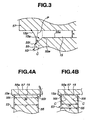
- a fillet angle ⁇ is an angle which is formed, in the section taken by the plane including the center axis of the cylindrical ceramic member 55, between the chamfer 55t and a tangent P which is tangential to the curved circumferential periphery 15p at the joint between the curved circumferential periphery 15p and the chamber 55t, the fillet ⁇ has a tendency to becoming large.
- the thickness T of the cylindrical ceramic member 55 is made smaller, i.e., the width W of the joining area is made smaller as shown in Fig. 4B , contraction of the solder layer 15 due to surface tension is not caused so much and therefore, as having described with reference to FIG. 3 , the overlying portion 15a becomes larger in volume so that a crack or the like defect C is more likely to be caused.
- the thickness T of the cylindrical ceramic member 55 is large to some extent, i.e., the width W of the joining area is large to some extent as shown in FIG. 4A , the solder is expanded while becoming thinner.
- the thickness t (mm) of the metallic cover member 57 so as to satisfy (1/120) x D ⁇ t ⁇ 3.
- the thickness t exceeds 3 mm, stress concentration on the ceramic member 55 side due to contraction of the metallic member is increased so as to cause a crack or the like defect in some case.
- the thickness t of the metallic cover member 57 becomes smaller than (1/120) x D, it is difficult for the metallic cover member 57 to have a desired strength.
- the metal-ceramic composite is not limited to use in the vacuum switch unit but can be applied to other devices, e.g., a heat exchanger.
- Sintered alumina bodies i.e., sintered body made of ceramic containing 92 wt% Alumina having various outer diameters D (mm) and various inner diameters d (mm) shown in Table 1 were prepared as the cylindrical ceramic member 55. Each sintered alumina body is formed with a chamfer of 0.25 mm at each of the inner and outer peripheral edges.
- Metallizing paste containing Mo-Mn alloy powder is applied to the opposite axial end surfaces of the cylindrical ceramic member and baked at the temperature of 1400 °C. Thereafter, the metallized axial end surfaces of the cylindrical ceramic member 55 is electroplated with Ni to form a metallizing layer 104 as shown in Fig. 5A . As shown in Fig.
- the metallic closure member 57 made of kovar and of the thickness determined variously in accordance with the diameter is placed upon the axial end surface of the cylindrical ceramic member 55 by interposing therebetween a Ag-Cu eutectic solder (alloy containing 28 wt% Cu and the remainder Ag) film 105 and soldered thereto at the temperature of 830 °C to form the butt seal structure.
- the width W of the joining area is adjusted by the size of the solder film 105. The appearances of the joining portions of the thus obtained examples were observed to examine whether a crack or the like defect was caused in the cylindrical ceramic member 55.
- the present invention was made as a result of an elaborate investigation conducted by the applicant who noticed the relation between the joining structure (i.e., edge seal structure or butt seal structure) and the size of the ceramic member at the time of joining the metallic member to the cylindrical ceramic member by way of the joining metal layer.
- the joining structure i.e., edge seal structure or butt seal structure
- the size of the ceramic member at the time of joining the metallic member to the cylindrical ceramic member by way of the joining metal layer.
- the edge seal structure inevitably requires the metallic member to have a hollow cylindrical portion at an end of which the metallic member is to be butt-joined to a ceramic member. Since a vacuum switch unit or the like device requires a metallic cover member for forming an enclosed inner space in addition to the metallic member having the hollow cylindrical portion, thus causing the necessity of an increased number of constituent parts and an increased man-hour, and therefore increasing the manufacturing cost.
- the butt seal structure only requires, for example, a metallic member in the form of a cover to be joined to an axial end surface of a ceramic member by interposing therebetween a solder layer,
- the butt seal structure is relatively simpler and can reduce the man-hour, i.e., the butt seal structure has a feature which the edge seal structure does not have.
Landscapes
- Chemical & Material Sciences (AREA)
- Engineering & Computer Science (AREA)
- Ceramic Engineering (AREA)
- Materials Engineering (AREA)
- Structural Engineering (AREA)
- Organic Chemistry (AREA)
- High-Tension Arc-Extinguishing Switches Without Spraying Means (AREA)
- Ceramic Products (AREA)
Claims (11)
- Metall-Keramik-Verbundkörper (53), der umfasst:ein hohles zylindrisches Keramikelement (55) mit einer axialen Abschlussfläche (55a);ein Metallelement (57) mit einem flachen Plattenabschnitt, der sich um einen gesamten Umfang der axialen Abschlussfläche (55a) des Keramikelementes (55) herum erstreckt, wobei das Metallelement (57) so angeordnet ist, dass eine Hauptfläche des Plattenabschnitts der axialen Abschlussfläche (55a) des Keramikelementes (55) gegenüber liegend angeordnet ist; und eine verbindende Metallschicht (15), die zwischen der Hauptfläche des Metallelementes (57) und der axialen Abschlussfläche (55a) des Keramikelementes (55) angeordnet ist und das Metallelement (57) sowie das Keramikelement (55) miteinander verbindet, um eine Stossdichtungsstruktur zu bilden;wobei die verbindende Metallschicht (15) und das Keramikelement (55) an einem ringförmigen Bereich miteinander in Kontakt sind, der sich in Umfangsrichtung der axialen Abschlussfläche (55a) des Keramikelementes (55) erstreckt und eine durchschnittliche Breite W (mm) hat; undwobei die durchschnittliche Breite W und ein Außendurchmesser D (mm) des Keramikelementes (55)

 dadurch gekennzeichnet, dassdas Keramikelement (55) innere und äußere Fasen (55t, 55t) an Innen- und Außenumfangsrändern der Abschlussfläche (55a) aufweist, wobei die verbindende Metallschicht (15) wenigstens einen Abschnitt der äußeren Fase (55t) überlappt.
 - Metall-Keramik-Verbundkörper (53) nach Anspruch 1, wobei der Plattenabschnitt des Metallelementes (57) die Dicke t (mm) hat, die

erfüllt. - Metall-Keramik-Verbundkörper (53) nach Anspruch 1 oder 2, wobei das Keramikelement (55) einen Teil eines Gehäuses (53) einer Vakuumschalteinheit (50) bildet.
- Metall-Keramik-Verbundkörper (53) nach einem der Ansprüche 1-3, wobei die verbindende Metallschicht (15) aus Lot besteht.
- Metall-Keramik-Verbundkörper (53) nach Anspruch 4, wobei das Lot eutektisches Ag-Cu Lot ist.
- Metall-Keramik-Verbundkörper (53) nach einem der Ansprüche 1-5, wobei das Keramikelement (55) aus Aluminiumoxidkeramik besteht und das Metallelement (57) aus Fe-Ni-Co-Legierung besteht.
- Vakuumschalteinheit (50), die umfasst:einen Metall-Keramik-Verbundkörper (53), in dem ein geschlossener Raum (11) ausgebildet ist; undein Paar Elektroden (52, 56) mit Kontakten (61, 60), die in dem geschlossenen Raum (11) angeordnet sind und aufeinander zu und voneinander weg bewegt werden können;wobei der Metall-Keramik-Verbundkörper (53) enthält:ein hohles zylindrisches Keramikelement (55), das einander gegenüberliegende axiale Abschlussflächen (55a, 55a) aufweist;ein Paar Verschlusselemente (57, 57) aus Metall, die die jeweiligen einander gegenüberliegenden axialen Abschlussflächen (55a, 55a) verschließen, wobei jedes der Verschlusselemente (57, 57) aus Metall einen flachen Plattenabschnitt aufweist, der sich über einen gesamten Umfang jeder der axialen Abschlussflächen (55a, 55a) des Keramikelementes (55) herum erstreckt, wobei jedes der Verschlusselemente (57, 57) aus Metall so angeordnet ist, dass eine Hauptfläche des Plattenabschnitts gegenüber jeder der axialen Abschlussflächen (55a, 55a) des Keramikelementes (55) angeordnet ist; undein Paar verbindender Metallschichten (15, 15), wobei jede der verbindenden Metallschichten (15, 15) zwischen der Hauptfläche jedes der Verschlusselemente (57, 57) aus Metall und jeder der axialen Abschlussflächen (55a, 55a) des Keramikelementes (55) angeordnet ist und jedes der Verschlusselemente (57, 57) aus Metall und das Keramikelement (55) miteinander verbindet, um eine Stossdichtungsstruktur zu bilden;wobei jede der verbindenden Metallschichten (15, 15) und das Keramikelement (55) an einem ringförmigen Bereich miteinander in Kontakt sind, der sich in Umfangsrichtung jeder der axialen Abschlussflächen (55a, 55a) des Keramikelementes (55) erstreckt und eine durchschnittliche Breite W (mm) hat,wobei die durchschnittliche Breite W und ein Außendurchmesser D (mm) des Keramikelementes (55)

 dadurch gekennzeichnet, dassdas Keramikelement (55) innere und äußere Fasen (55t, 55t) an Innen- und Außenumfangsrändern jeder der axialen Abschlussflächen (55a, 55a) aufweist, wobei jede der verbindenden Metallschichten (15, 15) wenigstens einen Abschnitt der äußeren Fase (55t, 55t) überlappt.
 - Vakuumschaltereinheit (50) nach Anspruch 7, wobei der Plattenabschnitt jedes der Verschlusselemente (20) aus Metall die Dicke t (mm) hat, die

- Vakuumschaltereinheit (50) nach Anspruch 7 oder 8, wobei die verbindenden Metallschichten (15, 15) aus Lot bestehen.
- Vakuumschaltereinheit (50) nach Anspruch 9, wobei das Lot eutektisches Ag-Cu-Lot ist.
- Vakuumschaltereinheit (50) nach einem der Ansprüche 7-10, wobei das Keramikelement (55) aus Aluminiumoxidkeramik besteht und die Verschlusselemente (57, 57) aus Metall aus Fe-Ni-Co-Legierung bestehen.
Applications Claiming Priority (2)
| Application Number | Priority Date | Filing Date | Title |
|---|---|---|---|
| JP2000365393A JP3690981B2 (ja) | 2000-11-30 | 2000-11-30 | 金属−セラミック接合体及びそれを用いた真空スイッチユニット |
| JP2000365393 | 2000-11-30 |
Publications (4)
| Publication Number | Publication Date |
|---|---|
| EP1211705A2 EP1211705A2 (de) | 2002-06-05 |
| EP1211705A3 EP1211705A3 (de) | 2004-08-18 |
| EP1211705B1 EP1211705B1 (de) | 2007-02-14 |
| EP1211705B2 true EP1211705B2 (de) | 2010-08-25 |
Family
ID=18836168
Family Applications (1)
| Application Number | Title | Priority Date | Filing Date |
|---|---|---|---|
| EP01128049A Expired - Lifetime EP1211705B2 (de) | 2000-11-30 | 2001-11-26 | Metall/keramik-komposit und diese verwendender Vakuumschalter |
Country Status (5)
| Country | Link |
|---|---|
| US (1) | US6635841B2 (de) |
| EP (1) | EP1211705B2 (de) |
| JP (1) | JP3690981B2 (de) |
| KR (1) | KR100459358B1 (de) |
| DE (1) | DE60126560T3 (de) |
Families Citing this family (6)
| Publication number | Priority date | Publication date | Assignee | Title |
|---|---|---|---|---|
| EP1587120B1 (de) | 2004-04-14 | 2007-05-30 | Ngk Spark Plug Co., Ltd | Schalterbehälter zur hermetischen Kapselung eines Schaltelements und Verfahren zu dessen Herstellung |
| JP4781446B2 (ja) * | 2009-03-27 | 2011-09-28 | 株式会社日立製作所 | 真空絶縁スイッチギヤ |
| FR2951314A1 (fr) * | 2009-10-12 | 2011-04-15 | Schneider Electric Ind Sas | Dispositif d'assemblage par brasage d'un capot d'extremite sur un corps cylindrique et ampoule a vide comportant un tel dispositif |
| US8632232B2 (en) * | 2010-03-31 | 2014-01-21 | Koito Manufacturing Co., Ltd. | Vehicular headlamp having a columnar light guide |
| JP6156625B2 (ja) * | 2013-03-13 | 2017-07-05 | オムロン株式会社 | 金属部品どうしの接合構造及びその接合方法 |
| DE102016125423A1 (de) * | 2016-12-22 | 2018-06-28 | Grohe Ag | Keramikbauteil, insbesondere Sanitärkeramikbauteil, sowie Bearbeitungswerkzeug zur Bearbeitung des Keramikbauteils |
Citations (1)
| Publication number | Priority date | Publication date | Assignee | Title |
|---|---|---|---|---|
| DE2633545B1 (de) † | 1976-07-26 | 1977-11-24 | Hermann Kirchmayer | Auslegerdrehlaufkatze |
Family Cites Families (7)
| Publication number | Priority date | Publication date | Assignee | Title |
|---|---|---|---|---|
| JPS5259863A (en) | 1975-11-11 | 1977-05-17 | Matsushita Electric Industrial Co Ltd | Method of producing vacuum switch valve |
| DE2633543C3 (de) | 1976-07-26 | 1980-10-16 | Siemens Ag, 1000 Berlin Und 8000 Muenchen | Vakuumschalter |
| DE3803227A1 (de) | 1988-02-04 | 1989-08-17 | Hoechst Ceram Tec Ag | Verfahren zum vakuumdichten verschliessen eines keramikrohres |
| JPH07172946A (ja) | 1993-12-15 | 1995-07-11 | Chichibu Onoda Cement Corp | セラミックス部材と金属部材の接合体 |
| EP1367039B1 (de) * | 2000-01-26 | 2005-11-16 | Ngk Spark Plug Co., Ltd | Keramisches Bauteil zum Verbinden, Verfahren zu seiner Herstellung, Vakuumschalter und Vakuumgefäss |
| KR100817376B1 (ko) * | 2000-10-31 | 2008-03-27 | 니혼도꾸슈도교 가부시키가이샤 | 진공 스위치용 용기, 진공 스위치, 진공 스위치용 용기의제조방법 및 진공 스위치의 제조방법 |
| JP3690979B2 (ja) * | 2000-11-30 | 2005-08-31 | 日本特殊陶業株式会社 | 金属−セラミック接合体及びそれを用いた真空スイッチユニット |
-
2000
- 2000-11-30 JP JP2000365393A patent/JP3690981B2/ja not_active Expired - Fee Related
-
2001
- 2001-11-26 EP EP01128049A patent/EP1211705B2/de not_active Expired - Lifetime
- 2001-11-26 DE DE60126560T patent/DE60126560T3/de not_active Expired - Lifetime
- 2001-11-29 US US09/995,735 patent/US6635841B2/en not_active Expired - Lifetime
- 2001-11-29 KR KR10-2001-0074803A patent/KR100459358B1/ko not_active Expired - Fee Related
Patent Citations (1)
| Publication number | Priority date | Publication date | Assignee | Title |
|---|---|---|---|---|
| DE2633545B1 (de) † | 1976-07-26 | 1977-11-24 | Hermann Kirchmayer | Auslegerdrehlaufkatze |
Also Published As
| Publication number | Publication date |
|---|---|
| DE60126560T2 (de) | 2007-06-06 |
| DE60126560T3 (de) | 2010-12-09 |
| KR20020042478A (ko) | 2002-06-05 |
| JP3690981B2 (ja) | 2005-08-31 |
| US20020092830A1 (en) | 2002-07-18 |
| JP2002167286A (ja) | 2002-06-11 |
| EP1211705A2 (de) | 2002-06-05 |
| KR100459358B1 (ko) | 2004-12-03 |
| DE60126560D1 (de) | 2007-03-29 |
| US6635841B2 (en) | 2003-10-21 |
| EP1211705B1 (de) | 2007-02-14 |
| EP1211705A3 (de) | 2004-08-18 |
Similar Documents
| Publication | Publication Date | Title |
|---|---|---|
| EP0087881B1 (de) | Verfahren zum Verbinden von Kupfer oder Kupfer-Chrom-Legierung mit Keramiken und Verbundene Formkörper aus Keramiken und Kupfer oder Kupfer-Chrom-Legierung | |
| EP1211705B2 (de) | Metall/keramik-komposit und diese verwendender Vakuumschalter | |
| US4528432A (en) | Vacuum interrupter | |
| US6566621B2 (en) | Metal-ceramic composite and vacuum switch unit using the same | |
| US5753876A (en) | Clad end seal for vacuum interrupter | |
| US4795866A (en) | Vacuum tube switch which uses low temperature solder | |
| JP3607552B2 (ja) | 金属−セラミック接合体及びその製造方法 | |
| KR870000722B1 (ko) | 세라믹스와 동재 또는 동-크롬합금재와의 접합 방법 | |
| JP4132032B2 (ja) | 真空容器の覗き窓および真空容器 | |
| JP4896316B2 (ja) | ガス封止形避雷器 | |
| JP2001220254A (ja) | 金属−セラミック接合体 | |
| JP7770247B2 (ja) | 真空バルブの製造方法 | |
| JP4545172B2 (ja) | 真空バルブ | |
| JPH1173859A (ja) | 真空バルブ | |
| JPS58199681A (ja) | 真空バルブの製造方法 | |
| JP2642386B2 (ja) | 真空バルブおよびその製造方法 | |
| JPH01102822A (ja) | 真空バルブの製造方法 | |
| JPH05290688A (ja) | 真空バルブ | |
| JPH06260065A (ja) | 真空バルブ | |
| JPH09231884A (ja) | 真空バルブ | |
| JPH0359921A (ja) | 真空バルブ | |
| JPS6273555A (ja) | 電解液電池の封着方法 | |
| JPH08310879A (ja) | 真空気密容器用封着材および真空気密容器 | |
| JPH01264127A (ja) | 真空バルブの製造方法 | |
| JPH01206527A (ja) | 真空バルブの製造方法 |
Legal Events
| Date | Code | Title | Description |
|---|---|---|---|
| PUAI | Public reference made under article 153(3) epc to a published international application that has entered the european phase |
Free format text: ORIGINAL CODE: 0009012 |
|
| AK | Designated contracting states |
Kind code of ref document: A2 Designated state(s): AT BE CH CY DE DK ES FI FR GB GR IE IT LI LU MC NL PT SE TR |
|
| AX | Request for extension of the european patent |
Free format text: AL;LT;LV;MK;RO;SI |
|
| PUAL | Search report despatched |
Free format text: ORIGINAL CODE: 0009013 |
|
| AK | Designated contracting states |
Kind code of ref document: A3 Designated state(s): AT BE CH CY DE DK ES FI FR GB GR IE IT LI LU MC NL PT SE TR |
|
| AX | Request for extension of the european patent |
Extension state: AL LT LV MK RO SI |
|
| RIC1 | Information provided on ipc code assigned before grant |
Ipc: 7H 01H 33/66 B Ipc: 7C 04B 37/02 A |
|
| 17P | Request for examination filed |
Effective date: 20040902 |
|
| AKX | Designation fees paid |
Designated state(s): DE FR GB NL |
|
| GRAP | Despatch of communication of intention to grant a patent |
Free format text: ORIGINAL CODE: EPIDOSNIGR1 |
|
| GRAS | Grant fee paid |
Free format text: ORIGINAL CODE: EPIDOSNIGR3 |
|
| GRAA | (expected) grant |
Free format text: ORIGINAL CODE: 0009210 |
|
| AK | Designated contracting states |
Kind code of ref document: B1 Designated state(s): DE FR GB NL |
|
| REG | Reference to a national code |
Ref country code: GB Ref legal event code: FG4D |
|
| REF | Corresponds to: |
Ref document number: 60126560 Country of ref document: DE Date of ref document: 20070329 Kind code of ref document: P |
|
| ET | Fr: translation filed | ||
| PLBI | Opposition filed |
Free format text: ORIGINAL CODE: 0009260 |
|
| PLAX | Notice of opposition and request to file observation + time limit sent |
Free format text: ORIGINAL CODE: EPIDOSNOBS2 |
|
| 26 | Opposition filed |
Opponent name: SIEMENS AG Effective date: 20071114 |
|
| NLR1 | Nl: opposition has been filed with the epo |
Opponent name: SIEMENS AG |
|
| PLAF | Information modified related to communication of a notice of opposition and request to file observations + time limit |
Free format text: ORIGINAL CODE: EPIDOSCOBS2 |
|
| PLAB | Opposition data, opponent's data or that of the opponent's representative modified |
Free format text: ORIGINAL CODE: 0009299OPPO |
|
| PLBB | Reply of patent proprietor to notice(s) of opposition received |
Free format text: ORIGINAL CODE: EPIDOSNOBS3 |
|
| PUAH | Patent maintained in amended form |
Free format text: ORIGINAL CODE: 0009272 |
|
| STAA | Information on the status of an ep patent application or granted ep patent |
Free format text: STATUS: PATENT MAINTAINED AS AMENDED |
|
| 27A | Patent maintained in amended form |
Effective date: 20100825 |
|
| AK | Designated contracting states |
Kind code of ref document: B2 Designated state(s): DE FR GB NL |
|
| REG | Reference to a national code |
Ref country code: NL Ref legal event code: T3 |
|
| REG | Reference to a national code |
Ref country code: FR Ref legal event code: PLFP Year of fee payment: 15 |
|
| REG | Reference to a national code |
Ref country code: FR Ref legal event code: PLFP Year of fee payment: 16 |
|
| REG | Reference to a national code |
Ref country code: FR Ref legal event code: PLFP Year of fee payment: 17 |
|
| PGFP | Annual fee paid to national office [announced via postgrant information from national office to epo] |
Ref country code: FR Payment date: 20171012 Year of fee payment: 17 Ref country code: DE Payment date: 20171121 Year of fee payment: 17 |
|
| PGFP | Annual fee paid to national office [announced via postgrant information from national office to epo] |
Ref country code: GB Payment date: 20171122 Year of fee payment: 17 Ref country code: NL Payment date: 20171016 Year of fee payment: 17 |
|
| REG | Reference to a national code |
Ref country code: DE Ref legal event code: R119 Ref document number: 60126560 Country of ref document: DE |
|
| REG | Reference to a national code |
Ref country code: NL Ref legal event code: MM Effective date: 20181201 |
|
| GBPC | Gb: european patent ceased through non-payment of renewal fee |
Effective date: 20181126 |
|
| PG25 | Lapsed in a contracting state [announced via postgrant information from national office to epo] |
Ref country code: NL Free format text: LAPSE BECAUSE OF NON-PAYMENT OF DUE FEES Effective date: 20181201 |
|
| PG25 | Lapsed in a contracting state [announced via postgrant information from national office to epo] |
Ref country code: FR Free format text: LAPSE BECAUSE OF NON-PAYMENT OF DUE FEES Effective date: 20181130 Ref country code: DE Free format text: LAPSE BECAUSE OF NON-PAYMENT OF DUE FEES Effective date: 20190601 |
|
| PG25 | Lapsed in a contracting state [announced via postgrant information from national office to epo] |
Ref country code: GB Free format text: LAPSE BECAUSE OF NON-PAYMENT OF DUE FEES Effective date: 20181126 |