EP1211542A2 - Anordnung zur visuellen und quantitativen 3-D-Untersuchung von Proben - Google Patents
Anordnung zur visuellen und quantitativen 3-D-Untersuchung von Proben Download PDFInfo
- Publication number
- EP1211542A2 EP1211542A2 EP01121978A EP01121978A EP1211542A2 EP 1211542 A2 EP1211542 A2 EP 1211542A2 EP 01121978 A EP01121978 A EP 01121978A EP 01121978 A EP01121978 A EP 01121978A EP 1211542 A2 EP1211542 A2 EP 1211542A2
- Authority
- EP
- European Patent Office
- Prior art keywords
- beam path
- sample
- stereomicroscope
- scanning device
- confocal scanning
- Prior art date
- Legal status (The legal status is an assumption and is not a legal conclusion. Google has not performed a legal analysis and makes no representation as to the accuracy of the status listed.)
- Granted
Links
- 230000000007 visual effect Effects 0.000 title claims abstract description 10
- 238000007689 inspection Methods 0.000 title 1
- 230000008878 coupling Effects 0.000 claims description 6
- 238000010168 coupling process Methods 0.000 claims description 6
- 238000005859 coupling reaction Methods 0.000 claims description 6
- 230000003287 optical effect Effects 0.000 claims description 6
- 238000005286 illumination Methods 0.000 claims description 3
- 238000000034 method Methods 0.000 description 7
- 238000001514 detection method Methods 0.000 description 5
- 238000011156 evaluation Methods 0.000 description 2
- 238000003384 imaging method Methods 0.000 description 2
- 238000000386 microscopy Methods 0.000 description 2
- 230000008569 process Effects 0.000 description 2
- 238000004458 analytical method Methods 0.000 description 1
- 230000008901 benefit Effects 0.000 description 1
- 229910052729 chemical element Inorganic materials 0.000 description 1
- 238000010226 confocal imaging Methods 0.000 description 1
- 238000013461 design Methods 0.000 description 1
- 238000004519 manufacturing process Methods 0.000 description 1
- 238000012067 mathematical method Methods 0.000 description 1
- 239000011159 matrix material Substances 0.000 description 1
- 238000005259 measurement Methods 0.000 description 1
- 230000007246 mechanism Effects 0.000 description 1
- 238000012986 modification Methods 0.000 description 1
- 230000004048 modification Effects 0.000 description 1
- 239000002245 particle Substances 0.000 description 1
- 238000011158 quantitative evaluation Methods 0.000 description 1
- 238000004621 scanning probe microscopy Methods 0.000 description 1
Images

Classifications
-
- G—PHYSICS
- G02—OPTICS
- G02B—OPTICAL ELEMENTS, SYSTEMS OR APPARATUS
- G02B21/00—Microscopes
- G02B21/18—Arrangements with more than one light path, e.g. for comparing two specimens
- G02B21/20—Binocular arrangements
- G02B21/22—Stereoscopic arrangements
-
- G—PHYSICS
- G02—OPTICS
- G02B—OPTICAL ELEMENTS, SYSTEMS OR APPARATUS
- G02B21/00—Microscopes
- G02B21/0004—Microscopes specially adapted for specific applications
- G02B21/002—Scanning microscopes
- G02B21/0024—Confocal scanning microscopes (CSOMs) or confocal "macroscopes"; Accessories which are not restricted to use with CSOMs, e.g. sample holders
- G02B21/0028—Confocal scanning microscopes (CSOMs) or confocal "macroscopes"; Accessories which are not restricted to use with CSOMs, e.g. sample holders specially adapted for specific applications, e.g. for endoscopes, ophthalmoscopes, attachments to conventional microscopes
Definitions
- the invention relates to an arrangement for visual and quantitative 3-D examination of samples .
- the invention relates to a Stereo microscope with a confocal scanner that parallel the visual Examination of samples as well as data acquisition with a confocal Scanner enabled.
- the basic structure of a stereo microscope is from the German Design registration 400 04 640.7 known. There are several Embodiments presented by a stereo microscope.
- the Stereomicroscope enables the visual three-dimensional observation of a Sample by the observer. If the picture is e.g. with a CCD camera recorded, the viewer only receives a two-dimensional image.
- the German patent application DE 196 32 637 discloses a method for Generation of parallactic sectional image stacks for the high-resolution Stereo microscopy.
- the method it is possible to make 3D animations of the spatial object by generating a series of slice stacks or to achieve sectional image stack pairs. This creates a stack of layplanes achieved by moving the depth of field of the microscope objective in discrete steps along the optical axis through the sample. So will won a batch of sectional images.
- the lay-up stack becomes one parallactic sectional image stack pair formed, the parallactic angle for stereoscopic vision.
- the 3-D representation of the pictures a display should, however, require considerable computing effort.
- the basic structure of a confocal scanning microscope with scanning device is from the U.S. Patent 4,863,266 known.
- the scanning microscope allows it to increase the resolution and contrast in three dimensions. Likewise can to get 3-D information from the object. Unfortunately, the device allows not a visual 3-D view of the sample to be examined.
- the invention has for its object to provide an arrangement that in addition to a visual 3-D observation of the sample, a quantitative 3-D analysis of the sample to be examined.
- the invention is also intended enable a 3-D representation of a sample with high quality and thereby the computational effort or other mathematical methods that a require considerable time to reduce.
- the objective problem is solved by an arrangement that thereby is characterized in that a confocal scanning device with the Stereomicroscope is connected to that of the confocal scanning device defined scan beam path scans a sample to be examined and records data for a 3-D image representation of the sample (6).
- An advantage of the invention is that with a stereo microscope both Visual as well as confocal scanning of the sample to be examined is possible. It is necessary to have a confocal scanning device connected to the stereomicroscope such that one of the confocal Scanning device defined scan beam path a sample to be examined scans and thereby data for a three-dimensional image representation of the Sample.
- the Stereophotography are dispensed with, the two illustrations of the object created different perspectives.
- the three-dimensional thus obtained Pictures are often of disappointing quality.
- these recordings elaborate to manufacture and require considerable consideration apparatus expenditure.
- Through the one connected to a stereo microscope confocal scanning device one can consecutively record multiple images create different levels of a sample. This data is e.g.
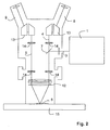
- the stereomicroscope 2 has a first and a second eyepiece 8 and 9, both in the first and second observation beam paths 4 and 5, respectively are arranged.
- a deflection prism 13 is used in each of the observation beam paths 4 and 5, which guides the observation beam path in the stereo microscope 2 accordingly.
- a plurality of tube lenses 14 are provided in the first and second observation beam paths 4 and 5. Downstream of the tube lenses 14 is an objective 12, which together images the first and second observation beam paths 4 and 5 onto a sample 6.
- the sample 6 can be located on an object support table 15, for example.
- the scanning device 1 defines a scanning beam path 3, which is also imaged onto the sample by the objective 12.
- FIG. 2 Another embodiment of the invention is shown in FIG. 2 . All elements of FIG. 2 that are identical to the elements of FIG. 1 are identified by the same reference numerals.
- the scanning device 1 is arranged with respect to the scanning microscope in such a way that the scanning beam path 3 can be coupled directly into one of the two observation beam paths 4 and 5.
- an optical coupling element 7 is provided in one of the observation beam paths 4 or 5, which leads the scan beam path 3 into an observation beam path.
- the scanning beam path 3 also passes through at least one of the tube lenses 14.
- the scanning beam path 3 and the illuminating beam paths 4 and 5 are imaged on the sample 6 by the objective 12.
- the optical coupling element 7 is coated in order to protect the observer from the illumination laser light of the scan beam reflected by the sample.
- confocal Scanning microscopy is used to scan a sample with a light beam.
- On confocal scanner or scanning device generally includes one Light source, a focusing optics with which the light of the light source on the a pinhole is focused, a scanning mechanism for Beam control, a detection aperture and detectors to detect the Detection and fluorescent light.
- the lens 12 is required to Imaging the scan beam onto the sample 6.
- an optical coupling element 7 is also shown (Beam splitter) required to scan the beam path 3 in the To couple observation beam path 4 or 5.
- the focus of the scan beam is generally done by tilting two mirrors in one plane within the sample 6 moves, the deflection axes usually perpendicular to each other stand so that one mirror deflects in the x and the other in the y direction.
- the mirror is tilted, for example, with the help of galvanometer actuators accomplished.
- the fluorescence from the sample or reflection light comes back through the same scanning mirror
- the invention has been made in relation to a particular embodiment the detection aperture, behind which detectors are focused, mostly Photomultiplier. Detection light that is not directly from the focus region comes from another light path and passes through the detection diaphragm not, so that one obtains point information which can be obtained by scanning the Sample leads to a three-dimensional image. Depth of field problems occur for reasons of principle not.
- the scanning device 1 is corresponding electronics (not shown) downstream, the quantitative three-dimensional imaging of the sample evaluates. There will be several levels in a row in a sample scanned, and the stacks so obtained are processed in a similar manner evaluated.
- the evaluation can e.g. even with a computer (not shown) and an appropriate computer software.
Landscapes
- Physics & Mathematics (AREA)
- Chemical & Material Sciences (AREA)
- Analytical Chemistry (AREA)
- General Physics & Mathematics (AREA)
- Optics & Photonics (AREA)
- Health & Medical Sciences (AREA)
- General Health & Medical Sciences (AREA)
- Ophthalmology & Optometry (AREA)
- Radiology & Medical Imaging (AREA)
- Surgery (AREA)
- Microscoopes, Condenser (AREA)
Abstract
Description
- Fig. 1
- eine schematische Darstellung der Ankopplung der konfokalen Scaneinrichtung durch den Kameraport, und
- Fig. 2
- eine schematische Darstellung eines Stereomikroskops, bei dem der Scanstrahlengang direkt in einen Beobachtungsstrahlengang eingekoppelt ist.
Claims (6)
- Anordnung zur visuellen und quantitativen 3-D-Untersuchung von Proben mit einem Stereomikroskop (2), das einen ersten und einen zweiten Beobachtungsstrahlengang (4, 5) definiert, dadurch gekennzeichnet, dass eine konfokale Scaneinrichtung (1) derart mit dem Stereomikroskop (10) verbunden ist, dass ein von der konfokalen Scaneinrichtung (1) definierter Scanstrahlengang (3) eine zu untersuchende Probe (6) abrastert und dabei Daten für eine drei-dimensionale Bilddarstellung der Probe (6) aufnimmt.
- Anordnung nach Anspruch 1, dadurch gekennzeichnet, dass die konfokalen Scaneinrichtung (1) derart an Stereomikroskop angebracht ist, dass der Scanstrahlengang (3) in den ersten oder in den zweiten Beobachtungsstrahlengang (4, 5) einkoppelbar ist.
- Anordnung nach Anspruch 2, dadurch gekennzeichnet, dass das ein optisches Einkoppelelement (7) vorgesehen ist, dass den Scanstrahlengang (3) in einen Beobachtungsstrahlengang (4, 5) ein- und auskoppelt.
- Anordnung nach Anspruch 1, dadurch gekennzeichnet, dass das Stereomikroskop mit einem Kameraport versehen ist, an den die konfokale Scaneinrichtung (1) den Scanstrahlengang (3) in das Stereomikroskop einkoppelt.
- Anordnung nach einem der Ansprüche 1 bis 4, dadurch gekennzeichnet, dass das der erste und der zweite Beleuchtungsstrahlengang (4, 5) und der Scanstrahlengang (3) durch ein Objektiv (12) des Stereomikroskops (2) gemeinsam auf die zu untersuchende Probe (6) abgebildet werden.
- Anordnung nach einem der Ansprüche 1 bis 5, dadurch gekennzeichnet, dass das die konfokale Scaneinrichtung (1) mit einem Computer verbunden ist, der die durch die konfokale Scaneinrichtung (1) aufgenommenen Bilddaten auswertet und auf einem Display darstellt.
Applications Claiming Priority (2)
| Application Number | Priority Date | Filing Date | Title |
|---|---|---|---|
| DE10055176A DE10055176B4 (de) | 2000-11-08 | 2000-11-08 | Anordnung zur visuellen und quantitativen 3-D-Untersuchung von Proben |
| DE10055176 | 2000-11-08 |
Publications (3)
| Publication Number | Publication Date |
|---|---|
| EP1211542A2 true EP1211542A2 (de) | 2002-06-05 |
| EP1211542A3 EP1211542A3 (de) | 2003-08-27 |
| EP1211542B1 EP1211542B1 (de) | 2005-11-16 |
Family
ID=7662452
Family Applications (1)
| Application Number | Title | Priority Date | Filing Date |
|---|---|---|---|
| EP01121978A Expired - Lifetime EP1211542B1 (de) | 2000-11-08 | 2001-09-13 | Anordnung zur visuellen und quantitativen 3-D-Untersuchung von Proben |
Country Status (3)
| Country | Link |
|---|---|
| US (1) | US20020054429A1 (de) |
| EP (1) | EP1211542B1 (de) |
| DE (2) | DE10055176B4 (de) |
Families Citing this family (7)
| Publication number | Priority date | Publication date | Assignee | Title |
|---|---|---|---|---|
| DE10204430A1 (de) * | 2002-02-04 | 2003-08-07 | Zeiss Carl | Stereo-Mikroskopieverfahren und Stereo-Mikroskopiesystem |
| US8339447B2 (en) * | 2004-10-21 | 2012-12-25 | Truevision Systems, Inc. | Stereoscopic electronic microscope workstation |
| DE102005008197A1 (de) * | 2005-02-22 | 2006-08-31 | Leica Microsystems Cms Gmbh | Mikroskop |
| US8358330B2 (en) * | 2005-10-21 | 2013-01-22 | True Vision Systems, Inc. | Stereoscopic electronic microscope workstation |
| DE102011000835C5 (de) * | 2011-02-21 | 2019-08-22 | Leica Microsystems Cms Gmbh | Abtastmikroskop und Verfahren zur lichtmikroskopischen Abbildung eines Objektes |
| JP5829030B2 (ja) * | 2011-03-23 | 2015-12-09 | オリンパス株式会社 | 顕微鏡 |
| EP3234681B1 (de) * | 2014-12-18 | 2020-02-26 | Rhode Island Hospital | Visualisierung von bakterieller kolonisation und biofilmbildung auf orthopädischen traumaexplantaten |
Family Cites Families (8)
| Publication number | Priority date | Publication date | Assignee | Title |
|---|---|---|---|---|
| US5161052A (en) * | 1991-03-29 | 1992-11-03 | Tandem Scanning Corporation | Steroscopic tandem scanning reflected light confocal microscope |
| US5896224A (en) * | 1994-08-30 | 1999-04-20 | Carl-Zeiss-Stiftung | Confocal microscope with a diaphragm disc having many transparent regions |
| JP3523348B2 (ja) * | 1994-11-08 | 2004-04-26 | 株式会社ニデック | 細隙灯顕微鏡 |
| DE69420569T2 (de) * | 1994-12-23 | 2000-05-04 | Koike Seiki Co | Konfokales Durchlichtlasermikroskop |
| DE19632637C2 (de) * | 1996-08-13 | 1999-09-02 | Schwertner | Verfahren zur Erzeugung parallaktischer Schnittbildstapelpaare für die hochauflösende Stereomikroskopie und/oder 3D-Animation mit konventionellen, nicht stereoskopischen Lichtmikroskopen |
| DE19640496A1 (de) * | 1996-10-01 | 1998-04-02 | Leica Lasertechnik | Verfahren zur Oberflächenvermessung mittels Konfokalmikroskopie |
| US6097538A (en) * | 1998-02-03 | 2000-08-01 | Olympus Optical Co., Ltd. | Lens barrel for use in a microscope |
| JP2000098259A (ja) * | 1998-09-22 | 2000-04-07 | Olympus Optical Co Ltd | 共焦点顕微鏡用撮影装置 |
-
2000
- 2000-11-08 DE DE10055176A patent/DE10055176B4/de not_active Expired - Fee Related
-
2001
- 2001-09-13 EP EP01121978A patent/EP1211542B1/de not_active Expired - Lifetime
- 2001-09-13 DE DE50108075T patent/DE50108075D1/de not_active Expired - Lifetime
- 2001-11-06 US US09/992,075 patent/US20020054429A1/en not_active Abandoned
Also Published As
| Publication number | Publication date |
|---|---|
| US20020054429A1 (en) | 2002-05-09 |
| DE10055176A1 (de) | 2002-05-23 |
| DE10055176B4 (de) | 2007-05-03 |
| DE50108075D1 (de) | 2005-12-22 |
| EP1211542A3 (de) | 2003-08-27 |
| EP1211542B1 (de) | 2005-11-16 |
Similar Documents
| Publication | Publication Date | Title |
|---|---|---|
| DE102018210603B4 (de) | Verfahren zum Erzeugen eines Übersichtsbilds unter Verwendung eines hochaperturigen Objektivs | |
| DE3610165C2 (de) | ||
| EP2887117B1 (de) | Mikroskop und Verfahren zur SPIM Mikroskopie | |
| DE69511903T2 (de) | System zur kontinnierlichen räumlichen Abbildung für Abtastmikroskopie | |
| EP3489735B1 (de) | Verfahren und anordnung zur lichtblattmikroskopie | |
| DE10027166B4 (de) | Stereoskopmikroskop | |
| DE102017101188B4 (de) | Mikroskop und Verfahren zum Mikroskopieren einer Probe | |
| EP3244249A2 (de) | Lichtblattmikroskop sowie verfahren zum betreiben eines lichtblattmikroskops | |
| DE3313789A1 (de) | Selbsttaetige mikroskopische untersuchungseinrichtung und verfahren zur ermittlung und wiederfindung von objekten in einem bild | |
| DE202005021436U1 (de) | Optisch verbessertes digitales Abbildungssystem | |
| DE102017100262A1 (de) | Verfahren zur Erzeugung eines dreidimensionalen Modells einer Probe in einem digitalen Mikroskop und digitales Mikroskop | |
| EP1420281A2 (de) | Verfahren und Anordnung zur tiefenaufgelösten optischen Erfassung einer Probe | |
| EP3447559B1 (de) | Hochauflösende 2d-mikroskopie mit verbesserter schnittdicke | |
| EP1178344B1 (de) | Verfahren und Vorrichtung zur Bildentzerrung in der Scanmikroskopie und Scanmikroskop | |
| DE102024124248A1 (de) | Mikroskop, verfahren zur bestimmung einer feldinhomogenität in einem sichtfeld eines mikroskops und mikroskopieverfahren | |
| WO2018234582A2 (de) | Mikroskopsystem mit lichtblattmikroskopischer funktionseinheit | |
| DE10118463A1 (de) | Verfahren und Anordnung zur tiefenaufgelösten optischen Erfassung einer Probe | |
| DE3623394C2 (de) | Operationsmikroskop | |
| WO2018141560A1 (de) | Verfahren zum bestimmen einer abweichung auf einem verschiebeweg einer zoom-optik und verfahren zur korrektur sowie bildaufnahmevorrichtung | |
| EP1211542B1 (de) | Anordnung zur visuellen und quantitativen 3-D-Untersuchung von Proben | |
| DE10029680B4 (de) | Mikroskop-Aufbau | |
| DE102015116598B4 (de) | Verfahren und Mikroskop zur hochauflösenden Abbildung mittels SIM | |
| WO2017207807A1 (de) | Lichtblattmikroskop und mikroskopisches verfahren mit einem lichtblattmikroskop | |
| DE102007047935A1 (de) | Vorrichtung und Verfahren zur Inspektion von Defekten am Randbereich eines Wafers und Verwendung der Vorrichtung in einer Inspektionseinrichtung für Wafer | |
| WO2000007056A1 (de) | Konfokales theta-mikroskop |
Legal Events
| Date | Code | Title | Description |
|---|---|---|---|
| PUAI | Public reference made under article 153(3) epc to a published international application that has entered the european phase |
Free format text: ORIGINAL CODE: 0009012 |
|
| AK | Designated contracting states |
Kind code of ref document: A2 Designated state(s): AT BE CH CY DE DK ES FI FR GB GR IE IT LI LU MC NL PT SE TR |
|
| AX | Request for extension of the european patent |
Free format text: AL;LT;LV;MK;RO;SI |
|
| PUAL | Search report despatched |
Free format text: ORIGINAL CODE: 0009013 |
|
| AK | Designated contracting states |
Designated state(s): AT BE CH CY DE DK ES FI FR GB GR IE IT LI LU MC NL PT SE TR |
|
| AX | Request for extension of the european patent |
Extension state: AL LT LV MK RO SI |
|
| 17P | Request for examination filed |
Effective date: 20040210 |
|
| 17Q | First examination report despatched |
Effective date: 20040308 |
|
| AKX | Designation fees paid |
Designated state(s): DE GB |
|
| GRAP | Despatch of communication of intention to grant a patent |
Free format text: ORIGINAL CODE: EPIDOSNIGR1 |
|
| GRAS | Grant fee paid |
Free format text: ORIGINAL CODE: EPIDOSNIGR3 |
|
| GRAA | (expected) grant |
Free format text: ORIGINAL CODE: 0009210 |
|
| AK | Designated contracting states |
Kind code of ref document: B1 Designated state(s): DE GB |
|
| REG | Reference to a national code |
Ref country code: GB Ref legal event code: FG4D Free format text: NOT ENGLISH |
|
| REF | Corresponds to: |
Ref document number: 50108075 Country of ref document: DE Date of ref document: 20051222 Kind code of ref document: P |
|
| GBT | Gb: translation of ep patent filed (gb section 77(6)(a)/1977) |
Effective date: 20060202 |
|
| RAP2 | Party data changed (patent owner data changed or rights of a patent transferred) |
Owner name: LEICA MICROSYSTEMS CMS GMBH |
|
| REG | Reference to a national code |
Ref country code: GB Ref legal event code: 732E |
|
| PLBE | No opposition filed within time limit |
Free format text: ORIGINAL CODE: 0009261 |
|
| STAA | Information on the status of an ep patent application or granted ep patent |
Free format text: STATUS: NO OPPOSITION FILED WITHIN TIME LIMIT |
|
| 26N | No opposition filed |
Effective date: 20060817 |
|
| PGFP | Annual fee paid to national office [announced via postgrant information from national office to epo] |
Ref country code: GB Payment date: 20190930 Year of fee payment: 19 |
|
| PGFP | Annual fee paid to national office [announced via postgrant information from national office to epo] |
Ref country code: DE Payment date: 20191129 Year of fee payment: 19 |
|
| REG | Reference to a national code |
Ref country code: DE Ref legal event code: R119 Ref document number: 50108075 Country of ref document: DE |
|
| GBPC | Gb: european patent ceased through non-payment of renewal fee |
Effective date: 20200913 |
|
| PG25 | Lapsed in a contracting state [announced via postgrant information from national office to epo] |
Ref country code: DE Free format text: LAPSE BECAUSE OF NON-PAYMENT OF DUE FEES Effective date: 20210401 |
|
| PG25 | Lapsed in a contracting state [announced via postgrant information from national office to epo] |
Ref country code: GB Free format text: LAPSE BECAUSE OF NON-PAYMENT OF DUE FEES Effective date: 20200913 |