EP1209504A2 - Méthode et dispositif pour balayer des objets microscopiques avec un système de balayage - Google Patents
Méthode et dispositif pour balayer des objets microscopiques avec un système de balayage Download PDFInfo
- Publication number
- EP1209504A2 EP1209504A2 EP01124653A EP01124653A EP1209504A2 EP 1209504 A2 EP1209504 A2 EP 1209504A2 EP 01124653 A EP01124653 A EP 01124653A EP 01124653 A EP01124653 A EP 01124653A EP 1209504 A2 EP1209504 A2 EP 1209504A2
- Authority
- EP
- European Patent Office
- Prior art keywords
- scan
- scanning
- examined
- sample table
- object area
- Prior art date
- Legal status (The legal status is an assumption and is not a legal conclusion. Google has not performed a legal analysis and makes no representation as to the accuracy of the status listed.)
- Granted
Links
Images


Classifications
-
- G—PHYSICS
- G02—OPTICS
- G02B—OPTICAL ELEMENTS, SYSTEMS OR APPARATUS
- G02B21/00—Microscopes
- G02B21/0004—Microscopes specially adapted for specific applications
- G02B21/002—Scanning microscopes
Definitions
- the invention relates to a method for scanning microscopic objects a scanning microscope, in particular with a confocal scanning microscope.
- the invention relates to a method for scanning a with an object located defining an x / y plane a scanning device that has optics and defines a scanning field, the object area of the object to be examined is incomplete includes.
- the invention further relates to an arrangement for examination microscopic objects that are larger than the scanning field of the microscope.
- the invention relates to an arrangement for scanning microscopic objects with a scanning device, an x / y plane defining sample table with which the microscopic object at least the x / y plane is displaceable, a light beam that is transmitted via a scan module and optics scan the object within a defined scan field and detects the light emanating from the object and a PC.
- neurons are currently being used in cell biology examined conventional light microscopes.
- the cells are often inclusive their dendrites larger than that essentially due to the opening width of the Objectively determined field size of the microscope. With lenses smaller Enlargement shows a larger field, but so that the required resolution is usually not achieved.
- the Scanning device can be formed by a scanning microscope. In the Scanning microscopy is used to illuminate a sample with a light beam to observe reflected or fluorescent light emitted by the sample.
- the focus of the illuminating light beam is controlled with the help of a Beam deflection device, generally by tilting two mirrors, in an object plane moves, the deflection axes mostly perpendicular stand on each other, so that one mirror in the x-, the other in the y-direction distracting.
- the mirror can be tilted, for example, with the help of Galvanometer actuators accomplished.
- the performance of the object coming light is dependent on the position of the scanning beam measured. Ideally describes the path of the scanning light beam on or a meander in the object. (Scan a line in the x direction at constant y position, then stop x scanning and by y adjustment Pan to the next line to be scanned and then at constant y position, scan this line in the negative x direction, etc.).
- a scanning microscope has the advantage of image data Saving the scanning area in order to follow the neighboring ones in the following steps Scanning areas.
- the object is created using a Sliding table successively shifted meandering.
- a Suitable software will then add the image data to the individual neighboring scan areas correspond, so linked together, that they can be put together to form an overall picture.
- the stage becomes This method is usually carried out automatically, computer-controlled, until the entire object level is scanned.
- the objects to be scanned are not flat, but three-dimensional objects, especially the documentation by manual signing significantly more difficult and sometimes too leads to unsatisfactory results.
- a confocal scanning microscope generally comprises a light source, focusing optics, with which the Light from the source is focused on a pinhole - the so-called excitation diaphragm is, a beam splitter, a beam deflector for beam control, a Optics, a detection aperture and the detectors to detect the Detection or fluorescent light.
- the illuminating light is over a Beam splitter coupled.
- the fluorescent or Reflection light comes back to the beam deflector Beam splitter, passes this to then on the detection aperture to be focused behind which the detectors are located. Detection light, that does not come directly from the focus region takes a different light path and does not pass the detection aperture, so you get a point information receives that by sequential. Scanning the object into one three-dimensional image leads. Usually a three-dimensional image is shown Image data acquisition achieved in layers. A scan field created by the Focusing optics is determined by a relative movement between the Move the sample table and the focusing optics accordingly. By means of this Relative movement is achieved that the scan field through examining object is moved in the z direction.
- the invention has for its object to provide a method that enables fast and efficient scanning of objects larger than that Scanning range of a microscope.
- Another object of the invention is to provide an arrangement with which larger microscopic object areas are possible quickly and efficiently scan. Furthermore, the arrangement should be designed such that the Image capture during the limited lifespan of biological specimens is possible.
- the above object is achieved by an arrangement that is characterized in that the scan field is set such that it is too investigating object area incompletely covered, and means are provided which move the sample table in such a way that the Variety of emerging scan fields the whole of interest Object area can be covered, and that the PC from the detected data of the individual scan fields of the object area to be examined Overall picture.
- An advantage of the invention is that objects that are larger than a current one Scan field can be captured effectively and quickly. It is from of particular importance that the invention is designed such that several Scan fields can be distributed over a sample area to be examined. at The distribution must ensure that each scan field has at least a part of the object to be examined. Scanning the to Examining object area is limited to Object structures. Scan fields that contain no object structures from the scanning process is not recorded. This leads to considerable time savings, since no fields are scanned, the background information only contain. The scanning process according to the invention is limited only scan fields containing information. Particularly advantageous is when the user gives me a label bypasses the investigating object area on the display or otherwise features. The multitude of scan fields that are necessary around the Detecting the enclosed object area are distributed automatically.
- the scanning device is a confocal scanning microscope. It goes without saying that a fully equipped scanning microscope is not absolutely necessary to scan a sample. Rather, it is sufficient to hold or position the necessary optical components for a scanning process in a suitable manner. The following description relates exclusively to a scanning microscope, but this should in no way be interpreted as a limitation of the invention.
- the light beam 3 coming from an illumination system 1 is reflected by a beam splitter 5 to the scan module 7, which contains a gimbal-mounted scan mirror 9 which guides the beam through the optics 13 over or through the object 15. In the case of non-transparent objects 15, the light beam 3 is guided over the object surface.
- the light beam 3 can also be guided through the object 15. This means that the light beam 3 is successively scanned from different focal planes of the object. The subsequent composition then gives a three-dimensional image of the object.
- the light beam 3 coming from the lighting system 1 is shown as a solid line in all the figures (FIGS. 1 to 2).
- the light 17 emanating from the object 15 passes through the optics 13 and via the scan module 7 to the beam splitter 5, passes it and hits the detector 19 which is designed as a photomultiplier.
- the light 17 emanating from the object 15 is shown in all figures (FIGS. 1 to 2) as a dashed line.
- Electrical detection signals 21, which are proportional to the power of the light emanating from the object 17, are generated in the detector 19 and transmitted to the processing unit 23.
- the position signals 25 detected in the scan module with the aid of an inductive or capacitive position sensor 11 are also transferred to the processing unit 23. It is obvious to a person skilled in the art that the position of the scanning mirror 9 can also be determined via the adjustment signals.
- the incoming analog signals are first digitized in the processing unit 23.
- the position and detection signals are in the processing unit 23 assigned to each other and put together to form an image 29, which on the Display 27 is shown. That with a confocal scanning microscope Illuminated pinhole 39 and the like that are usually provided Detection pinhole 41 are schematic for completeness located. Are omitted because of the better clarity however, some optical elements for guiding and shaping the Light beams. These are a specialist working in this field well known.
- the adjustment device 40 includes three not shown Adjusting motors that move the sample table 35 in every spatial direction can.
- the target data entered via the joystick is saved by the PC 34 taken into account when creating the image 29.
- the device is like this designed that the sample table 35 after a certain adjustment stops and further entry of target data with the joystick until complete scanning at the set position prevented. Only after the table can be completely scanned at the set position be repositioned. All image data obtained are stored in the PC 34 in an overall image data record.
- FIG. 2 shows an embodiment analogous to FIG. 1 with manual table control.
- the sample table 35 is moved using the usual traversing screws, not shown here.
- the position of the sample table 35 is continuously detected using the table position sensor 31 and passed on to the control unit 23.
- a movement of the sample table 35 is always possible, the scanning being carried out continuously. Distortions that would be caused by moving the sample table are corrected by the PC 34.
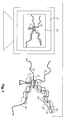
- FIG. 3 schematically shows a sequence of the method.
- a cell 51 with dendrites 50 is shown.
- a first scan field 52 1 is scanned.
- the user selects another scan area, which is then scanned.
- the overlap area 54 is consequently scanned twice, which leads to the optimal assignment of position and detection data of the two scan fields 52 1 and 52 2 in the image data processing.
- the user can cover an object area 55 to be examined with a plurality of scan fields 52 1 , 52 2 and 52 n .
- An overall image is composed of the individual scan fields 52 1 , 52 2 and 52 n .
- the scan fields overlap area 54 of the respective scan fields are scanned twice, which leads to an optimal assignment of the position and detection data.
- FIG. 4 shows a further embodiment for scanning an object area 55 to be examined.
- the object area 55 to be examined is determined by means of a marking means, such as the joystick 33.
- the object 55 to be examined is bypassed with the marking means, thereby defining a boundary line 56 within which the plurality of scan fields 52 1 , 52 2 and 52 n are automatically distributed.
- the structures of interest are enclosed by the large number of scan fields 52 1 , 52 2 and 52 n .
Landscapes
- Physics & Mathematics (AREA)
- Chemical & Material Sciences (AREA)
- Analytical Chemistry (AREA)
- General Physics & Mathematics (AREA)
- Optics & Photonics (AREA)
- Microscoopes, Condenser (AREA)
Applications Claiming Priority (2)
| Application Number | Priority Date | Filing Date | Title |
|---|---|---|---|
| DE10058100 | 2000-11-23 | ||
| DE10058100.5A DE10058100B4 (de) | 2000-11-23 | 2000-11-23 | Verfahren und eine Anordnung zur Abtastung mikroskopischer Objekte mit einer Scaneinrichtung |
Publications (3)
| Publication Number | Publication Date |
|---|---|
| EP1209504A2 true EP1209504A2 (fr) | 2002-05-29 |
| EP1209504A3 EP1209504A3 (fr) | 2004-04-21 |
| EP1209504B1 EP1209504B1 (fr) | 2007-05-09 |
Family
ID=7664343
Family Applications (1)
| Application Number | Title | Priority Date | Filing Date |
|---|---|---|---|
| EP01124653A Expired - Lifetime EP1209504B1 (fr) | 2000-11-23 | 2001-10-16 | Méthode et dispositif pour balayer des objets microscopiques avec un système de balayage |
Country Status (3)
| Country | Link |
|---|---|
| US (1) | US6852964B2 (fr) |
| EP (1) | EP1209504B1 (fr) |
| DE (2) | DE10058100B4 (fr) |
Cited By (3)
| Publication number | Priority date | Publication date | Assignee | Title |
|---|---|---|---|---|
| EP2053441A1 (fr) * | 2007-10-22 | 2009-04-29 | Jasco Corporation | Appareil de mesure microscopique |
| DE102008010435A1 (de) * | 2008-02-21 | 2009-09-03 | Tecan Trading Ag | Datenerfassungsverfahren mit einem Laser Scanner-Gerät |
| DE102010040611A1 (de) * | 2010-09-13 | 2012-03-15 | Sulfurcell Solartechnik Gmbh | Spektrometer zur Erfassung opto-elektronischer Materialeigenschaften einer Halbleiterprobe |
Families Citing this family (3)
| Publication number | Priority date | Publication date | Assignee | Title |
|---|---|---|---|---|
| DE102004034988A1 (de) | 2004-07-16 | 2006-02-02 | Carl Zeiss Jena Gmbh | Lichtrastermikroskop und Verwendung |
| WO2018089839A1 (fr) | 2016-11-10 | 2018-05-17 | The Trustees Of Columbia University In The City Of New York | Procédés d'imagerie rapide de grands échantillons à haute résolution |
| DE102018127076A1 (de) | 2018-10-30 | 2020-04-30 | Leica Instruments (Singapore) Pte. Ltd. | Mikroskopsystem zur Abbildung eines Probenbereichs und entsprechendes Verfahren |
Citations (1)
| Publication number | Priority date | Publication date | Assignee | Title |
|---|---|---|---|---|
| WO1996037797A1 (fr) * | 1995-05-26 | 1996-11-28 | General Scanning, Inc. | Microscope a large champ de vision et systeme de balayage utile avec ce microscope |
Family Cites Families (8)
| Publication number | Priority date | Publication date | Assignee | Title |
|---|---|---|---|---|
| DE3718066A1 (de) * | 1987-05-29 | 1988-12-08 | Zeiss Carl Fa | Verfahren zur mikroinjektion in zellen bzw. zum absaugen aus einzelnen zellen oder ganzer zellen aus zellkulturen |
| US4827141A (en) * | 1987-10-26 | 1989-05-02 | Hughes Aircraft Company | Subresolution element spatial measurement technique |
| DE4417944A1 (de) * | 1994-05-21 | 1995-11-23 | Zeiss Carl Fa | Verfahren zum Korrelieren verschiedener Koordinatensysteme in der rechnergestützten, stereotaktischen Chirurgie |
| US5844598A (en) * | 1996-01-17 | 1998-12-01 | Pixel Vision, Inc. | CCD based optical detector for a confocal microscope |
| US6272235B1 (en) * | 1997-03-03 | 2001-08-07 | Bacus Research Laboratories, Inc. | Method and apparatus for creating a virtual microscope slide |
| US6134009A (en) * | 1997-11-07 | 2000-10-17 | Lucid, Inc. | Imaging system using polarization effects to enhance image quality |
| US6134010A (en) * | 1997-11-07 | 2000-10-17 | Lucid, Inc. | Imaging system using polarization effects to enhance image quality |
| US20030133009A1 (en) * | 1999-04-09 | 2003-07-17 | Carl S Brown | System and method for detecting with high resolution a large, high content field |
-
2000
- 2000-11-23 DE DE10058100.5A patent/DE10058100B4/de not_active Expired - Fee Related
-
2001
- 2001-10-16 EP EP01124653A patent/EP1209504B1/fr not_active Expired - Lifetime
- 2001-10-16 DE DE50112477T patent/DE50112477D1/de not_active Expired - Lifetime
- 2001-11-19 US US09/989,275 patent/US6852964B2/en not_active Expired - Lifetime
Patent Citations (1)
| Publication number | Priority date | Publication date | Assignee | Title |
|---|---|---|---|---|
| WO1996037797A1 (fr) * | 1995-05-26 | 1996-11-28 | General Scanning, Inc. | Microscope a large champ de vision et systeme de balayage utile avec ce microscope |
Non-Patent Citations (2)
| Title |
|---|
| "Three-Dimensional and Multidimensional Microscopy: Image Acquisition and Processing V" PROC. SPIE - INT. SOC. OPT. ENG. (USA), PROCEEDINGS OF THE SPIE - THE INTERNATIONAL SOCIETY FOR OPTICAL ENGINEERING, 1998, SPIE-INT. SOC. OPT. ENG, USA, Bd. 3261, 1998, Seiten 177-184, XP002270445 ISSN: 0277-786X * |
| STEINER G E ET AL: "Automated data acquisition by confocal laser scanning microscopy and image analysis of triple stained immunofluorescent leukocytes in tissue" JOURNAL OF IMMUNOLOGICAL METHODS, ELSEVIER SCIENCE PUBLISHERS B.V.,AMSTERDAM, NL, Bd. 237, Nr. 1-2, April 2000 (2000-04), Seiten 39-50, XP004192493 ISSN: 0022-1759 * |
Cited By (6)
| Publication number | Priority date | Publication date | Assignee | Title |
|---|---|---|---|---|
| EP2053441A1 (fr) * | 2007-10-22 | 2009-04-29 | Jasco Corporation | Appareil de mesure microscopique |
| US7869039B2 (en) | 2007-10-22 | 2011-01-11 | Jasco Corporation | Microscopic-measurement apparatus |
| DE102008010435A1 (de) * | 2008-02-21 | 2009-09-03 | Tecan Trading Ag | Datenerfassungsverfahren mit einem Laser Scanner-Gerät |
| DE102008010435B4 (de) * | 2008-02-21 | 2010-07-29 | Tecan Trading Ag | Datenerfassungsverfahren mit einem Laser Scanner-Gerät |
| US8222615B2 (en) | 2008-02-21 | 2012-07-17 | Tecan Trading Ag | Data acquisition method using a laser scanner |
| DE102010040611A1 (de) * | 2010-09-13 | 2012-03-15 | Sulfurcell Solartechnik Gmbh | Spektrometer zur Erfassung opto-elektronischer Materialeigenschaften einer Halbleiterprobe |
Also Published As
| Publication number | Publication date |
|---|---|
| EP1209504B1 (fr) | 2007-05-09 |
| EP1209504A3 (fr) | 2004-04-21 |
| DE10058100A1 (de) | 2002-06-06 |
| DE50112477D1 (de) | 2007-06-21 |
| US6852964B2 (en) | 2005-02-08 |
| DE10058100B4 (de) | 2017-07-13 |
| US20020060285A1 (en) | 2002-05-23 |
Similar Documents
| Publication | Publication Date | Title |
|---|---|---|
| EP1186930B1 (fr) | Appareil pour investigation et manipulation d'objects microscopiques | |
| EP2195697B1 (fr) | Procédé pour l'analyse d'un échantillon | |
| EP1946173B1 (fr) | Dispositif de manipulation d'echantillons | |
| EP1664888B1 (fr) | Microscope a balayage avec eclairage evanescent | |
| DE10050529B4 (de) | Verfahren zur Strahlsteuerung in einem Scanmikroskop, Anordnung zur Strahlsteuerung in einem Scanmikroskop und Scanmikroskop | |
| DE10043992B4 (de) | Verfahren zur Untersuchung einer Probe und konfokales Scan-Mikroskop | |
| DE102012022603B3 (de) | Vorrichtung und Verfahren zur Mikroskopie einer Vielzahl von Proben | |
| DE102013216938B3 (de) | Verfahren zur Kalibrierung einer Laserablenkeinrichtung einesLasermikrodissektionssystems und Lasermikrodissektionssystem | |
| DE102018210603A1 (de) | Verfahren zum Erzeugen eines Übersichtsbilds unter Verwendung eines hochaperturigen Objektivs | |
| DE10139920B4 (de) | Scanmikroskop und Verfahren zum Scannen eines Objekts | |
| EP1178344B1 (fr) | Méthode et appareil pour la restitution d'image pour la microscopie à balayage et microscope à balayage | |
| DE102005047200B4 (de) | Verfahren zur Korrektur einer Steuerung eines optischen Scanners in einer Vorrichtung zur scannenden Abbildung einer Probe und Vorrichtung zur Erzeugung eines Bildes einer Probe durch Abscannen der Probe | |
| DE10118463A1 (de) | Verfahren und Anordnung zur tiefenaufgelösten optischen Erfassung einer Probe | |
| DE102018131427B4 (de) | Verfahren zur automatischen Positionsermittlung auf einer Probenanordnung und entsprechendes Mikroskop, Computerprogramm und Computerprogrammprodukt | |
| DE102014118025B4 (de) | Vorrichtung zur Lichtblattmikroskopie | |
| DE10058100B4 (de) | Verfahren und eine Anordnung zur Abtastung mikroskopischer Objekte mit einer Scaneinrichtung | |
| DE10115578A1 (de) | Verfahren und Anordnung zum Ausgleichen von Abbildungsfehlern | |
| DE10233549B4 (de) | Scanmikroskop mit Manipulationslichtstrahl und Verfahren zur Scanmikroskopie | |
| EP3988989B1 (fr) | Procédé et microscope doté d'un dispositif de détection des déplacements d'un échantillon par rapport à une lentille | |
| EP1373961B1 (fr) | Ensemble objectif de microscope | |
| DE102021104871A1 (de) | Verfahren und Vorrichtung zur lichtblattmikroskopischen Untersuchung einer Probe | |
| DE10247249A1 (de) | Scanmikroskop mit einem Spiegel zur Einkopplung eines Manipulationslichtstrahls | |
| DE102019119147A1 (de) | Mikroskop und verfahren zur mikroskopie | |
| DE20205079U1 (de) | Variable Lochblende und konfokales Scanmikroskop | |
| DE10309911B4 (de) | Verfahren zur Ermittlung eines Farblängsfehlers eines Scanmikroskops und Scanmikroskop |
Legal Events
| Date | Code | Title | Description |
|---|---|---|---|
| PUAI | Public reference made under article 153(3) epc to a published international application that has entered the european phase |
Free format text: ORIGINAL CODE: 0009012 |
|
| AK | Designated contracting states |
Kind code of ref document: A2 Designated state(s): AT BE CH CY DE DK ES FI FR GB GR IE IT LI LU MC NL PT SE TR |
|
| AX | Request for extension of the european patent |
Free format text: AL;LT;LV;MK;RO;SI |
|
| PUAL | Search report despatched |
Free format text: ORIGINAL CODE: 0009013 |
|
| AK | Designated contracting states |
Kind code of ref document: A3 Designated state(s): AT BE CH CY DE DK ES FI FR GB GR IE IT LI LU MC NL PT SE TR |
|
| AX | Request for extension of the european patent |
Extension state: AL LT LV MK RO SI |
|
| 17P | Request for examination filed |
Effective date: 20040928 |
|
| 17Q | First examination report despatched |
Effective date: 20041111 |
|
| AKX | Designation fees paid |
Designated state(s): DE GB |
|
| RAP1 | Party data changed (applicant data changed or rights of an application transferred) |
Owner name: LEICA MICROSYSTEMS CMS GMBH |
|
| GRAP | Despatch of communication of intention to grant a patent |
Free format text: ORIGINAL CODE: EPIDOSNIGR1 |
|
| GRAS | Grant fee paid |
Free format text: ORIGINAL CODE: EPIDOSNIGR3 |
|
| GRAA | (expected) grant |
Free format text: ORIGINAL CODE: 0009210 |
|
| AK | Designated contracting states |
Kind code of ref document: B1 Designated state(s): DE GB |
|
| REG | Reference to a national code |
Ref country code: GB Ref legal event code: FG4D Free format text: NOT ENGLISH |
|
| REF | Corresponds to: |
Ref document number: 50112477 Country of ref document: DE Date of ref document: 20070621 Kind code of ref document: P |
|
| GBT | Gb: translation of ep patent filed (gb section 77(6)(a)/1977) |
Effective date: 20070705 |
|
| PLBE | No opposition filed within time limit |
Free format text: ORIGINAL CODE: 0009261 |
|
| STAA | Information on the status of an ep patent application or granted ep patent |
Free format text: STATUS: NO OPPOSITION FILED WITHIN TIME LIMIT |
|
| 26N | No opposition filed |
Effective date: 20080212 |
|
| PGFP | Annual fee paid to national office [announced via postgrant information from national office to epo] |
Ref country code: GB Payment date: 20201027 Year of fee payment: 20 |
|
| PGFP | Annual fee paid to national office [announced via postgrant information from national office to epo] |
Ref country code: DE Payment date: 20201228 Year of fee payment: 20 |
|
| REG | Reference to a national code |
Ref country code: DE Ref legal event code: R071 Ref document number: 50112477 Country of ref document: DE |
|
| REG | Reference to a national code |
Ref country code: GB Ref legal event code: PE20 Expiry date: 20211015 |
|
| PG25 | Lapsed in a contracting state [announced via postgrant information from national office to epo] |
Ref country code: GB Free format text: LAPSE BECAUSE OF EXPIRATION OF PROTECTION Effective date: 20211015 |