EP1209487B1 - Verfahren und Vorrichtung zur Erfassung von Objekten, mit Hintergrundausblendung - Google Patents
Verfahren und Vorrichtung zur Erfassung von Objekten, mit Hintergrundausblendung Download PDFInfo
- Publication number
- EP1209487B1 EP1209487B1 EP01127862A EP01127862A EP1209487B1 EP 1209487 B1 EP1209487 B1 EP 1209487B1 EP 01127862 A EP01127862 A EP 01127862A EP 01127862 A EP01127862 A EP 01127862A EP 1209487 B1 EP1209487 B1 EP 1209487B1
- Authority
- EP
- European Patent Office
- Prior art keywords
- background elimination
- elimination device
- position signals
- determined
- output
- Prior art date
- Legal status (The legal status is an assumption and is not a legal conclusion. Google has not performed a legal analysis and makes no representation as to the accuracy of the status listed.)
- Expired - Lifetime
Links
- 230000008030 elimination Effects 0.000 title claims abstract description 92
- 238000003379 elimination reaction Methods 0.000 title claims abstract description 92
- 238000000034 method Methods 0.000 title claims abstract description 19
- 238000001514 detection method Methods 0.000 title description 17
- 230000003321 amplification Effects 0.000 claims abstract description 41
- 238000003199 nucleic acid amplification method Methods 0.000 claims abstract description 41
- 238000005259 measurement Methods 0.000 claims 2
- 230000005693 optoelectronics Effects 0.000 abstract description 3
- 230000007704 transition Effects 0.000 description 8
- 230000003287 optical effect Effects 0.000 description 4
- 230000007717 exclusion Effects 0.000 description 2
- 238000004458 analytical method Methods 0.000 description 1
- 238000010586 diagram Methods 0.000 description 1
- 239000000523 sample Substances 0.000 description 1
Images
Classifications
-
- G—PHYSICS
- G01—MEASURING; TESTING
- G01S—RADIO DIRECTION-FINDING; RADIO NAVIGATION; DETERMINING DISTANCE OR VELOCITY BY USE OF RADIO WAVES; LOCATING OR PRESENCE-DETECTING BY USE OF THE REFLECTION OR RERADIATION OF RADIO WAVES; ANALOGOUS ARRANGEMENTS USING OTHER WAVES
- G01S17/00—Systems using the reflection or reradiation of electromagnetic waves other than radio waves, e.g. lidar systems
- G01S17/02—Systems using the reflection of electromagnetic waves other than radio waves
- G01S17/06—Systems determining position data of a target
- G01S17/46—Indirect determination of position data
- G01S17/48—Active triangulation systems, i.e. using the transmission and reflection of electromagnetic waves other than radio waves
-
- G—PHYSICS
- G01—MEASURING; TESTING
- G01S—RADIO DIRECTION-FINDING; RADIO NAVIGATION; DETERMINING DISTANCE OR VELOCITY BY USE OF RADIO WAVES; LOCATING OR PRESENCE-DETECTING BY USE OF THE REFLECTION OR RERADIATION OF RADIO WAVES; ANALOGOUS ARRANGEMENTS USING OTHER WAVES
- G01S17/00—Systems using the reflection or reradiation of electromagnetic waves other than radio waves, e.g. lidar systems
- G01S17/02—Systems using the reflection of electromagnetic waves other than radio waves
- G01S17/04—Systems determining the presence of a target
-
- G—PHYSICS
- G01—MEASURING; TESTING
- G01S—RADIO DIRECTION-FINDING; RADIO NAVIGATION; DETERMINING DISTANCE OR VELOCITY BY USE OF RADIO WAVES; LOCATING OR PRESENCE-DETECTING BY USE OF THE REFLECTION OR RERADIATION OF RADIO WAVES; ANALOGOUS ARRANGEMENTS USING OTHER WAVES
- G01S7/00—Details of systems according to groups G01S13/00, G01S15/00, G01S17/00
- G01S7/48—Details of systems according to groups G01S13/00, G01S15/00, G01S17/00 of systems according to group G01S17/00
- G01S7/483—Details of pulse systems
- G01S7/486—Receivers
Definitions
- the present invention relates to a method and to a device for detection of an object, with background elimination.
- a photoelectric sensor which can detect the presence of an object within a pre-determined interval of distances, normally indicated by the term "field”, is generally known as a background elimination device.
- the background elimination device can detect the presence of an object within an interval of distances contained between the background elimination device itself and a pre-determined limit threshold, beyond which the presence of any object is ignored.
- the background elimination devices comprise a photoemitter, which can emit a beam of light pulses in a specific direction for detection of objects, a photoreceiver of the PSD (Position Sensitive Device) type, which, via an optical triangulation system, can receive partially the beam of light pulses reflected by an object, in order to supply as output a first and a second electrical signal, the values of which together have correlation with the position of the beam of pulses which meets a surface presented by the photoreceiver.
- PSD Position Sensitive Device
- the background elimination device additionally comprises a switching circuit, which is connected to the photoreceiver, and can process the first and second electrical signals, in order to supply as output an information signal, the logic state of which indicates the presence or absence of an object within the "field".
- the switching circuit comprises an amplification stage, which is connected to the photoreceiver, and can amplify and/or attenuate selectively the first and/or the second signal, such as to permit regulation of the limit threshold, a high-gain differential stage, which is connected to the amplification stage, and can supply as output a differential electrical signal, the value of which is determined by the difference between the first and the second signal, and a comparator stage, which is connected to the differential stage, and, according to the comparison between the value of the differential signal and a pre-defined switching threshold, can supply as output the electrical information signal, which has alternatively a first or a second logic state, indicating respectively the presence or absence of any object within the "field".
- the information signal which is generated by the comparator device has the first logic state, whereas otherwise the information signal has the second logic state.
- condition according to which the information signal goes from one logic state to the other defines the limit threshold present between the "field” and an interval of non-detection, which extends between the limit threshold and infinity.
- the background elimination device can or can not detect an object located at the limit threshold, according to its reflective power.
- the photoreceiver supplies as output a single value other than zero, of the first and of the second signal. This condition signifies that the object is present at the limit threshold.
- the photoreceiver supplies as output a single value of zero, of the first and of the second signal. This condition occurs in the absence of objects.
- the comparator stage receives as input a differential signal with a value of zero, giving rise to a state of indeterminateness or instability of the background elimination device.
- DE4311691 discloses a method for adjusting an optical distance probe consists in that the output currents of a position-sensitive optodetector are controllably amplified and the difference between the amplified output currents is made to vanish by appropriately controlling the amplification.
- US5225689 discloses a reflected light sensor having a light transmitter including at least two mutually independent light sources and a light receiver including at least two separately evaluatable photosensitive elements.
- a switching point or distance limit of the light sensor can be continuously varied within a defined sensing range by inversely and continuously controlling currents of the light sources in accordance with a control voltage USt, LED, or by continuously varying a first and a second independent control voltage thereby controlling gains of signals at the output of the photosensitive elements.
- the object of the present invention is thus to provide a background elimination device which is free from the above-described disadvantages.
- a background elimination device is provided, as described in claim 1.
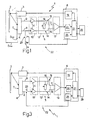
- 1 indicates as a whole a background elimination device which can detect the presence of an object 2 within a pre-determined interval of distances.
- this pre-determined interval of distances is generally known as the "field”, and is defined by the space contained between a minimum distance Dmin, and a maximum distance Dmax, measured from the background elimination device 1.
- the background elimination device 1 can ignore the presence of any object which is located at a distance shorter than the minimum distance Dmin, or at a distance greater than the maximum distance Dmax, which will be indicated hereinafter as the "limit threshold".
- the background elimination device 1 comprises an optoelectronic device for emission of light, in this case a photoemitter 3, which can generate as output, in a pre-determined direction, and according to a control signal received as input, a light beam comprising a sequence of light pulses; and an optoelectronic reception device, in this case a photoreceiver 4, which, via an optical triangulation system, can receive the light beam reflected by the object 2, in order to supply as output a pair of electrical position signals, the values of which together have correlation with the distance of the object 2 itself, measured relative to the background elimination device 1.
- a photoemitter 3 which can generate as output, in a pre-determined direction, and according to a control signal received as input, a light beam comprising a sequence of light pulses
- an optoelectronic reception device in this case a photoreceiver 4, which, via an optical triangulation system, can receive the light beam reflected by the object 2, in order to supply as output a pair of electrical position signals, the
- the background elimination device 1 additionally comprises a differential circuit 5, which is connected downstream from the photoreceiver 4, and can process the pair of electrical position signals supplied by the photoreceiver 4 itself, in order to supply as output a differential signal which has a value indicative of the distance of. the object 2; and a processing device 6, which can receive the differential signal, and compare it with a pre-determined switching signal, in order to supply as output an information signal which has a first, or alternatively a second logic state, indicating respectively a condition of presence or absence of the object 2 within the "field".
- a differential circuit 5 which is connected downstream from the photoreceiver 4, and can process the pair of electrical position signals supplied by the photoreceiver 4 itself, in order to supply as output a differential signal which has a value indicative of the distance of. the object 2
- a processing device 6 which can receive the differential signal, and compare it with a pre-determined switching signal, in order to supply as output an information signal which has a first, or alternatively a second logic state, indicating respectively
- the photoreceiver 4 is advantageously defined by a sensor of a known type, generally indicated by the abbreviation "PSD" (Position Sensitive Device), which has a surface 7 which is sensitive to the position of the incident light beam, and comprises a first and second output terminal 8, 9.
- PSD Position Sensitive Device
- the photoreceiver 4 can supply at the first and second terminals 8, 9, respectively a first and a second electrical position signal, the (current) values of which together have correlation with the position of incidence on the surface 7 of the light beam reflected by the object 2.
- the photoreceiver 4 is positioned relative to the photoemitter 3, such as to provide accurate optical triangulation of the light beam for emission and reception, thus defining a univocal ratio between the position of the point of incidence of the light beam on the surface 7 of the photoreceiver 4, and the distance of the object 2 measured relative to the background elimination device 1.
- This ratio thus provides a correlation between the distance of the object 2 from the background elimination device 1, and the two values relative to the first and second position signals.
- the differential circuit 5 comprises an amplification stage 10, which is of a known type, and can be defined for example by a pair of amplification circuits 11 (illustrated schematically), which can receive as input respectively the first and the second position signal, in order to provide amplification of the latter as output; and a regulator stage 12, which is connected to the photoreceiver 4 via the amplification stage 10, and can permit regulation of the "limit threshold".
- amplification stage 10 which is of a known type, and can be defined for example by a pair of amplification circuits 11 (illustrated schematically), which can receive as input respectively the first and the second position signal, in order to provide amplification of the latter as output; and a regulator stage 12, which is connected to the photoreceiver 4 via the amplification stage 10, and can permit regulation of the "limit threshold".
- the differential circuit 5 additionally comprises a differential stage 13, which is connected downstream from the regulator stage 12, from which it receives the first and the second position signal, and can supply as output the differential signal, which is determined by the amplification of the difference of potential present between the first and the second signal.
- the amplification stage 10 and the regulator stage 12 define a first and a second amplification "channel" 14, 15 with variable gain, which connect the input terminals of the differential stage 13 to the output terminals of the photoreceiver 4, i.e. which connect the first and second output terminals 8, 9 of the photoreceiver 4, respectively to a first and a second input terminal 16, 17 of the differential stage 13.
- the regulator stage 12 comprises a variable resistance resistor 18 (indicated schematically) of a known type, for example a manual regulation multi-revolution unit or a digital trimmer, by means of which it is possible to control the variation of the "limit threshold" in a known manner, by means of unbalancing of the amplification in the first and second amplification channels 14, 15.
- a variable resistance resistor 18 indicated schematically
- a manual regulation multi-revolution unit or a digital trimmer by means of which it is possible to control the variation of the "limit threshold" in a known manner, by means of unbalancing of the amplification in the first and second amplification channels 14, 15.
- the differential stage 13 receives the first and second suitably unbalanced position signals of the regulator stage 12, and supplies the processing device 6 with the differential signal.
- the processing device 6 comprises a synchronisation unit 19, which can generate the control signal which controls the emission of the light pulses from the photoemitter 3, and a comparison unit 20, which can receive the differential signal, and compare the latter with the switching threshold, such as to supply as output a detection signal, the logic state of which indicates the presence or absence of the object 2 within the "field".
- the comparison unit 20 has a switching threshold which has a pre-determined reference voltage, which for example is zero, and, according to the voltage value of the differential signal, controls the transition of the detection signal from one logic state to the other.
- the processing device 6 additionally comprises a central control unit 21, which can coordinate and control the operations carried out both by the comparison unit 20, and by the synchronisation unit 19.
- the central control unit 21 can receive the detection signal from the comparison unit 20, in order to. supply as output the information signal which indicates the presence/absence of the object within the "field".
- the background elimination device 1 can be provided with an interface unit 29, which cooperates with the processing device 6, and can permit variation of the resistance of the resistor 18.
- the interface unit 29 can advantageously be defined by a circuit of a known type, comprising a regulation push button and a display unit which can display the value of the "limit threshold".
- the background elimination device 1 is also provided with a preliminary search circuit, which can search for the presence/absence of an object at the background elimination device 1, before the latter carries out the detection of the arrangement of the object within the "field".
- the background elimination device 1 is provided with a selection unit 25, which cooperates with the central control unit 21, and can control selectively the opening/closure of the switch 23, thus giving rise to selection of one of the following functioning modes of the background elimination device 1.
- a “background elimination” functioning mode in which the background elimination device 1 can detect the presence/absence of an object 2 within the pre-determined "field", i.e. which can detect the arrangement of the object 2 itself, by measuring the distance, and comparing the latter with the limit threshold.
- a "sensing" functioning mode in which the background elimination device 1 can carry out a preliminary search, in order to detect only the presence or absence of an object 2, independently from the distance of the latter.
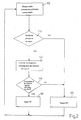
- block 100 is reached, in which, via the photoemitter 3, the central control unit 21 commands emission of a beam of light pulses; for the sake of descriptive simplicity, the emission of a sequence defined by a first and a second pulse is taken into consideration.
- the central control unit 21 commands closure of the switch 23, thus giving rise to transition of the background elimination device 1 from the "background elimination" functioning mode to the "sensing" functioning mode, in which the preliminary search for the object 2 is activated.
- Block 100 is followed by block 110, in which the presence/absence of an object is verified.
- closure of the switch 23 gives rise to "exclusion" of the first channel, i.e. to "setting” of the pre-determined potential V RF (for example zero), at the first position signal at the first input terminal 16 of the differential stage 13; in this condition, the functioning of the differential circuit 5 is limited to amplification of the second channel 15, since the differential signal output by the differential stage 13 corresponds to the difference between the value of the second signal, suitably amplified, and the pre-determined potential V RF .
- V RF for example zero
- the background elimination device 1 has the second signal, and thus the differential signal, with a value other than zero, whereas in the opposite case, i.e. in the absence of objects, the second signal, and thus the differential signal, have a value of zero.
- the comparison unit 20 can provide an indication of presence or absence of the object 2.
- the central control unit 21 verifies the logic state of the detection signal. If the detection signal has the logic state which indicates the absence of objects, block 110 is followed by block 120, in which, via the information signal, the central control unit 21 provides an indication of the absence of objects.
- any subsequent analysis of the second pulse emitted by the photoemitter 3 is prevented, since the lack of objects at any distance has been ascertained via block 110.
- Block 120 is followed by block 100, in which a new emission cycle, and thus new "sensing", is reiterated.
- block 110 is followed by block 130, in which, via the selection unit 25, the central control unit 21 commands opening of the switch 23, and thus transition from the "sensing" functioning mode to the "background elimination” functioning mode.
- the background elimination device 1 detects the second light pulse.
- Opening of the switch 23 makes it possible to determine the distance of the object 2 from the background elimination device 1.
- Block 130 is followed by block 140, in which it is verified whether the object 2 detected is disposed within the "field".
- the photoreceiver 4 supplies as input to the differential circuit 5 the first and second signals, which are amplified in the two respective channels 14, 15, and are supplied to the input of the differential stage 13, which supplies the differential signal as output.
- the comparison unit 20 carries out the comparison between the differential signal and the switching threshold, supplying as output the detection signal by means of which the central control unit 21 is able to supply the information signal which indicates the absence or presence of the object 2 in the "field".
- block 140 is followed by block 150, whereas otherwise, block 140 is followed by block 120.
- Block 150 is followed by block 100, in which a new detection cycle is reiterated.
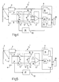
- the condition of "setting" the pre-determined potential V RF in the first channel which gives rise to transition from the "background elimination” functioning mode to the "sensing" functioning mode, can be obtained by setting the pre-determined potential V RF at any point of the first amplification channel, i.e. by connecting the switch 23 between any point of the first amplification channel 14 and the terminal 24.
- the switch 23 can be connected between the terminal 24 and a connection point contained between the amplification stage 10 and the regulator stage 12, or between the terminal 24 and the first input terminal 16 of the differential stage 13.
- the transition from the "background elimination" functioning mode, to the "sensing" functioning mode can be obtained by setting the pre-determined potential V RF at any point of the second amplification channel, i.e. by connecting the switch 23 between any point of the second amplification channel 14 and the terminal 24.
- the presence/absence of the object is detected by means of processing of the first signal, whereas the pre-determined potential V RF is set at the second signal, by means of the "exclusion" of the second channel 15.
- the background elimination device 1 has a circuit configuration in which the switch 23 of the sensing circuit 22 has one terminal which is connected to an input of the differential circuit 5, and the opposite terminal which is connected to the first output terminal 8 of the photoreceiver 4.
- the central control unit 21 commands closure/opening of the switch 23, thus giving rise to transition of the background elimination device 1 from the "background elimination” functioning mode, to the "sensing" functioning mode.
- opening of the switch 23 gives rise to "setting" of a zero value (of current or voltage) in the first channel 14, and consequently, in this case also, similarly to the above-described functioning, to the amplification and processing of a differential signal which contains only the information concerning the presence/absence of an object supplied by the second channel 15.
- the condition of "setting" a zero value (of current or voltage) in the first channel 14, which gives rise to transition from the "background elimination” functioning mode to the "sensing" functioning mode, can be obtained by interrupting the passage of current at any point of the first amplification channel; consequently, the switch 23 can be positioned at any point of the first amplification channel 14.
- the switch 23 can be interposed between the amplification stage 10 and the regulator stage 12, or between the first input terminal 16 of the differential stage 13, and an output of the regulator stage 12.
- the switch 23 can be connected at any point of the second amplification channel 15, thus giving rise to the same functioning of the background elimination device 1.
- a potential with a value of zero is set at the second signal, whereas only the first signal is amplified and processed, such as to detect the presence of the object.
- the sensing circuit 22 of the background elimination device 1 does not have the switch 23, and has an unbalance device 26, which can vary the amplification of the first channel 14 according to a control signal supplied by the selection unit 25.
- the second signal is processed, whereas the first signal is excluded by setting a pre-determined potential V RF in the first channel.
- the attenuation can be obtained, for example, by means of regulation of the gain of one of the amplifiers 11 (illustrated schematically), which are present in the amplification stage 10, or by means of corresponding regulation of the differential stage 13.
- the sensing circuit 22 of the background elimination device 4 does not have either the unbalance device 26 or the selection unit 25, and is provided with a measuring unit 27, which can detect the value of the first signal present at the output terminal 8 of the photoreceiver 4, in order to supply to the central control unit 21 a signal which indicates the presence/absence of an object.
- the background elimination device 1 measures the value of the signal at the first terminal 8, and if the presence of the object is detected, it changes to the "background elimination" functioning mode.
- the measuring device 27 sends a signal which indicates the absence of an object 2, to the central control unit 21, which supplies as output the information signal which indicates the absence of the object 2 within the "field", whereas in the opposite case, i.e. if the value of the first signal is other than zero, the measuring device 27 sends a signal which indicates the presence of an object, to the central control unit 21, which commands transition of the background elimination device 1 to the "background elimination" functioning mode, in which, similarly to the above-described variants, it is verified whether the object 2 is within or outside the "field".
- the measuring device 27 can detect the first signal at any point of the first amplification channel 14.
- the measuring device 27 can detect the second signal at any point of the second amplification channel 15.
- the measuring device 27 can be connected to the first and second amplification channels 14, 15, in order to detect and process the values respectively of the first and second signals, such as to supply to the central control unit 21 a signal which indicates the presence/absence of the object.
- the background elimination device 1 has the advantage that it is accurate, i.e. it can switch the information signal which indicates the presence/absence of the object within the "field", according to the distance of the object to be detected, and independently from the reflective power of the latter.
- the background elimination device 1 has the advantage that it is structurally simple and economical.
- the background elimination device 1 can make a direct comparison between the information obtained during the "background elimination” functioning mode, and during the "sensing" functioning mode.
- the background elimination device 1 can check that the items of information are compatible with one another; for example if they are in use, during the "background elimination” functioning mode and in the "sensing" functioning mode, there is detection respectively of the presence of an object or absence of an object within the "field”, and the background elimination device 1 supplies as output the absence of the object within the "field”, whereas if the information is compatible, the background elimination device 1 supplies as output the information signal obtained during the "background elimination" functioning mode.
- the "sensing" functioning mode can precede or follow the "background elimination” functioning mode.
Landscapes
- Physics & Mathematics (AREA)
- Engineering & Computer Science (AREA)
- Electromagnetism (AREA)
- Computer Networks & Wireless Communication (AREA)
- General Physics & Mathematics (AREA)
- Radar, Positioning & Navigation (AREA)
- Remote Sensing (AREA)
- Geophysics And Detection Of Objects (AREA)
Claims (17)
- Hintergrundeliminierungsvorrichtung (1) zum Detektieren der Anwesenheit eines Objektes innerhalb eines vorher bestimmten Intervalls von Distanzen, die zwischen der Hintergrundeliminierungsvorrichtung (1) selbst und einer vorbestimmten Grenzschwelle vorhanden sind;
wobei die Hintergrundeliminierungsvorrichtung (1) Folgendes aufweist:einen Fotoemitter (3), der einen Strahl von Lichtimpulsen in einer vorher bestimmten Richtung emittiert;einen Fotoempfänger (4), der einen Strahl von Lichtimpulsen empfängt, die von einem Objekt reflektiert werden, und als Ausgangsgröße ein Paar von Positionssignalen liefert, die die Distanz des Objektes (2) von der Hintergrundeliminierungsvorrichtung (1) anzeigen; wobei der Fotoempfänger (4) eine Oberfläche (7) hat, die empfindlich für die Position des auftreffenden Lichtstrahls ist und einen ersten und einen zweiten Ausgangsanschluss (8, 9) aufweist, um die Positionssignale zu liefern:ein Paar von Verstärkungskanälen (14, 15), welches die Positionssignale verstärkt, und Verarbeitungsmittel (6), die die Positionssignale vom Fotoempfänger (4) über die Verstärkungskanäle (14, 15) empfangen, und die gemäß den Positionssignalen als Ausgangsgröße ein erstes Informationssignal liefern, welches die Anordnung eines Objektes (2) innerhalb des vorbestimmten Intervalls von Distanzen anzeigt; wobei die Hintergrundeliminierungsvorrichtung dadurch gekennzeichnet ist, dass sie Folgendes aufweist:Vorsuchmittel (22), die temporär nur eines der Positionssignale verarbeiten, um als Ausgangsgröße ein zweites Informationssignal zu liefern, welches nur die Anwesenheit/Abwesenheit eines Objektes (2) unabhängig von der Distanz des Objektes (2) von der Hintergrundeliminierungsvorrichtung (1) anzeigt; undMittel zum Ausführen eines Vergleichs zwischen dem ersten und dem zweiten Informationssignal, um die Anordnung des Objektes innerhalb des vorbestimmten Intervalls von Distanzen zu überprüfen. - Hintergrundeliminierungsvorrichtung nach Anspruch 1, die dadurch gekennzeichnet ist, dass die Vorsuchmittel (22) Ungleichgewichtsmittel (26) und Auswahlmittel (25) aufweisen, die die Ungleichgewichtsmittel (26) steuern, um temporär einen der Verstärkungskanäle (14, 15) auszuschließen und eines der Positionssignale auf einen vorbestimmten Wert (VRF) zu setzen; wobei die Verarbeitungsmittel (6) fähig sind, das zweite Informationssignal, welches die Anwesenheit/Abwesenheit eines Objektes (2) anzeigt, als Ausgangsgröße zu liefern, und zwar durch Verarbeitung des Positionssignals, welches in dem nicht veränderten Kanal (15, 14) vorhanden ist.
- Hintergrundeliminierungsvorrichtung nach Anspruch 1, dadurch gekennzeichnet, dass die Vorsuchmittel (22) Schaltmittel (23) und Auswahlmittel (25) aufweisen, die die Schaltmittel (23) schalten können, um einen der Verstärkungskanäle (14, 15) temporär auszuschließen, und um eines der Positionssignale auf einen vorbestimmten Wert (VRF) zu setzen; wobei die Verarbeitungsmittel (6) fähig sind, das zweite Informationssignal, welches die Anwesenheit/Abwesenheit eines Objektes (2) anzeigt, als Ausgangsgröße zu liefern, und zwar durch Verarbeitung des Positionssignals, welches in dem eingeschlossenen Kanal (15, 14) vorhanden ist.
- Hintergrundeliminierungsvorrichtung nach Anspruch 3, dadurch gekennzeichnet, dass die Auswahlmittel (25) das selektive Öffnen von einem der Verstärkungskanäle (14, 15) anweisen, und zwar durch Schalten der Schaltmittel (23), um den Verstärkungskanal (14, 15) selbst auszuschließen.
- Hintergrundeliminierungsvorrichtung nach Anspruch 4, wobei die Schaltmittel (23) einen Schalter (23) aufweisen, der zwischen einem Ausgangsanschluss (8) des Fotoempfängers (4) und einem der Verstärkungskanäle (14, 15) angeschlossen ist.
- Hintergrundeliminierungsvorrichtung nach Anspruch 3, dadurch gekennzeichnet, dass die Auswahlmittel (25) das Schließen von einem der Verstärkungskanäle (14, 15) bei einem vorbestimmten Potenzial (VRF) selektiv anweisen, und zwar durch Schalten der Schaltmittel (23) zum Ausschließen des Verstärkungskanals (14, 15).
- Hintergrundeliminierungsvorrichtung nach Anspruch 6, wobei die Schaltmittel (23) einen Schalter (23) aufweisen, der zwischen einem Ausgangsanschluss (8) des Fotoempfängers (4) und einem Erdungsanschluss (24) mit einem vorbestimmten Potenzial (VRF) angeschlossen ist.
- Hintergrundeliminierungsvorrichtung nach Anspruch 3, wobei die Auswahlmittel (25) selektiv das Öffnen/Schließen der Schaltmittel (23) steuern, um einen der folgenden Betriebszustände auszuwählen:einen Hintergrundeliminierungsbetriebszustand, in dem die Hintergrundeliminierungsvorrichtung (1) die Anwesenheit/Abwesenheit eines Objektes (2) in dem vorbestimmten Intervall von Distanzen detektiert;und einen Abfühlbetriebszustand, in dem die Hintergrundeliminierungsvorrichtung (1) eine Vorsuche ausführt, um nur die Anwesenheit/Abwesenheit eines Objektes (2) unabhängig von der Distanz des Objektes von der Hintergrundeliminierungsvorrichtung (1) auszuführen.
- Hintergrundeliminierungsvorrichtung nach Anspruch 1, dadurch gekennzeichnet, dass die Vorsuchmittel (22) Messmittel (27) aufweisen, die mit einem der Verstärkungskanäle (14, 15) verbunden sind, um das jeweilige Positionssignal zu messen; wobei die Messmittel (27) geeignet sind, um das gemessene Positionssignal zu verarbeiten, um das erwähnte zweite Informationssignal zu den Verarbeitungsmitteln (6) zu liefern, welches die Anwesenheit/Abwesenheit eines Objektes unabhängig von der Distanz des Objektes (2) von der Hintergrundeliminierungsvorrichtung anzeigt.
- Verfahren zum Detektieren der Anwesenheit/Abwesenheit eines Objektes innerhalb eines vorbestimmten Intervalls von Distanzen, welches Folgende Schritte aufweist:Aussenden eines Strahls von Lichtimpulsen in einer vorbestimmten Richtung durch einen Fotoemitter (3);Empfangen eines Lichtstrahls, der von einem Objekt reflektiert wurde, mit einem Fotoempfänger (4), um als Ausgangsgröße ein Paar von Positionssignalen zu liefern, welche die Distanz eines Objektes relativ zu einem vorbestimmten Referenzpunkt anzeigen; wobei der Fotoempfänger (4) eine Oberfläche (7) hat, die empfindlich für die Position des auftreffenden Lichtstrahls ist, und einen ersten und einen zweiten Ausgangsanschluss (8, 9) aufweist, um die Positionssignale zu liefern;Verarbeiten (140) des Positionssignals, um als eine Ausgangsgröße ein erstes Informationssignal zu liefern, welches die Anordnung eines Objektes (2) innerhalb des vorbestimmten Intervalls von Distanzen anzeigt;wobei das Verfahren dadurch gekennzeichnet ist, dass es die folgenden Schritte aufweist:Ausführen einer Vorsuche (110) für das Objekt, bei der nur eines der Positionssignale verarbeitet wird, um als eine Ausgangsgröße ein zweites Informationssignal zu liefern, welches nur die Anwesenheit/Abwesenheit eines Objektes unabhängig von der Distanz des Objektes (2) von dem vorbestimmten Referenzpunkt anzeigt; undAusführen eines Vergleiches zwischen dem ersten und dem zweiten Informationssignal, um die Anordnung des Objektes innerhalb des vorbestimmten Intervalls von Distanzen zu überprüfen.
- Verfahren nach Anspruch 10, dadurch gekennzeichnet, dass der Vorsuchschritt (110) den Schritt aufweist, eines der Positionssignale zu verändern, um es auf einen vorbestimmten Signalwert (VRF) zu setzen.
- Verfahren nach Anspruch 10 oder 11, dadurch gekennzeichnet, dass der Vorsuchschritt (110) den Schritt aufweist, durch Schaltmittel (23) einen Ausgangsanschluss (8) des Fotoempfängers (4) zu öffnen.
- Verfahren nach Anspruch 10 oder 11, dadurch gekennzeichnet, dass der Vorsuchschritt (110) den Schritt aufweist, durch Schaltmittel (23) einen Ausgangsanschluss (8) des Fotoempfängers (4) mit einem Anschluss (24) mit einem vorbestimmten Potenzial (VRF) zu verbinden.
- Verfahren nach Anspruch 10, dadurch gekennzeichnet, dass der Vorsuchschritt (110) den Schritt aufweist, eines der Positionssignale zu messen.
- Verfahren nach einem der Ansprüche 10 bis 14, dadurch gekennzeichnet, dass der Vorsuchschritt (110) dem Schritt der Verarbeitung (140) der Positionssignale vorangeht.
- Verfahren nach einem der Ansprüche 10 bis 15, dadurch gekennzeichnet, dass der Schritt der Verarbeitung (140) des Paares von Positionssignalen gemäß der Anzeige der Anwesenheit des zweiten Informationssignals ausgeführt wird.
- Verfahren nach Anspruch 14, dadurch gekennzeichnet, dass der Schritt der Verarbeitung (140) des Paares von Positionssignalen dem Vorsuchschritt (110) folgt, falls der Vorsuchschritt (110) detektiert, dass das Objekt vorhanden ist, und zwar um als Ausgangsgröße das erste Informationssignal zu liefern, welches die Anordnung eines Objektes (2) innerhalb des vorbestimmten Intervalls von Distanzen anzeigt.
Applications Claiming Priority (2)
| Application Number | Priority Date | Filing Date | Title |
|---|---|---|---|
| ITBO000691 | 2000-11-24 | ||
| IT2000BO000691A ITBO20000691A1 (it) | 2000-11-24 | 2000-11-24 | Metodo e dispositivo per la rilevazione di un oggetto con soppressione di sfondo |
Publications (2)
| Publication Number | Publication Date |
|---|---|
| EP1209487A1 EP1209487A1 (de) | 2002-05-29 |
| EP1209487B1 true EP1209487B1 (de) | 2010-10-27 |
Family
ID=11438881
Family Applications (1)
| Application Number | Title | Priority Date | Filing Date |
|---|---|---|---|
| EP01127862A Expired - Lifetime EP1209487B1 (de) | 2000-11-24 | 2001-11-22 | Verfahren und Vorrichtung zur Erfassung von Objekten, mit Hintergrundausblendung |
Country Status (4)
| Country | Link |
|---|---|
| EP (1) | EP1209487B1 (de) |
| AT (1) | ATE486292T1 (de) |
| DE (1) | DE60143341D1 (de) |
| IT (1) | ITBO20000691A1 (de) |
Families Citing this family (6)
| Publication number | Priority date | Publication date | Assignee | Title |
|---|---|---|---|---|
| DK1528411T3 (da) * | 2003-10-27 | 2010-05-17 | Bea Sa | Sensor til afstandsmåling |
| RU2324199C1 (ru) * | 2006-10-30 | 2008-05-10 | Открытое акционерное общество "Научно-производственный испытательный центр "АРМИНТ" | Электронно-цифровое устройство измерения угловых координат быстро движущихся объектов |
| CN102679949A (zh) * | 2012-05-17 | 2012-09-19 | 北京中远通科技有限公司 | 一种直接发射型物体检测系统及方法 |
| ITUB20154173A1 (it) | 2015-10-01 | 2017-04-01 | Datalogic IP Tech Srl | Sensore optoelettronico e metodo di funzionamento di un sensore optoelettronico |
| CN105372661A (zh) * | 2015-10-15 | 2016-03-02 | 南昌航空大学 | 一种超声波智能测距仪 |
| DE102023111796B4 (de) * | 2023-05-05 | 2024-12-19 | Wenglor sensoric elektronische Geräte GmbH | Optischer näherungsschalter und verfahren zur erfassung der unterschreitung eines mindestabstands |
Family Cites Families (3)
| Publication number | Priority date | Publication date | Assignee | Title |
|---|---|---|---|---|
| DE4040225C2 (de) * | 1990-12-15 | 1994-01-05 | Leuze Electronic Gmbh & Co | Reflexions-Lichttaster |
| DE4311691C2 (de) * | 1993-04-08 | 1996-07-04 | Sick Erwin Gmbh | Verfahren zum Justieren eines Lichtabstandstasters und Lichtabstandstaster |
| DE4419032A1 (de) * | 1994-05-31 | 1996-01-25 | Sick Optik Elektronik Erwin | Lichttaster mit Hintergrundausblendung, realisiert nach dem Quotientenverfahren |
-
2000
- 2000-11-24 IT IT2000BO000691A patent/ITBO20000691A1/it unknown
-
2001
- 2001-11-22 AT AT01127862T patent/ATE486292T1/de not_active IP Right Cessation
- 2001-11-22 EP EP01127862A patent/EP1209487B1/de not_active Expired - Lifetime
- 2001-11-22 DE DE60143341T patent/DE60143341D1/de not_active Expired - Lifetime
Also Published As
| Publication number | Publication date |
|---|---|
| DE60143341D1 (de) | 2010-12-09 |
| ITBO20000691A1 (it) | 2002-05-24 |
| EP1209487A1 (de) | 2002-05-29 |
| ITBO20000691A0 (it) | 2000-11-24 |
| ATE486292T1 (de) | 2010-11-15 |
Similar Documents
| Publication | Publication Date | Title |
|---|---|---|
| US6211784B1 (en) | Object detector and object detector system | |
| US6124936A (en) | Color discrimination system | |
| EP0974208B1 (de) | Signalempfänger zum empfang von signalen, die von einer sonde ausgesendet werden | |
| KR100622959B1 (ko) | 분리형 광전 스위치 | |
| EP1209487B1 (de) | Verfahren und Vorrichtung zur Erfassung von Objekten, mit Hintergrundausblendung | |
| JPS6123910A (ja) | 光式距離測定装置 | |
| US5508645A (en) | Circuit for raising a minimum threshold of a signal detector | |
| US5986255A (en) | Photoelectric cell with lockable differential processing | |
| JPH08201519A (ja) | 光受信回路 | |
| EP1209447B2 (de) | Lichtdetektor und zugehörige lichtdetektierende IC-Karte | |
| JPH07174666A (ja) | パルス幅とゲインを自動設定するotdr | |
| JP2958371B2 (ja) | 光電センサの動作条件調整装置及びその動作条件調整方法 | |
| JPH05325065A (ja) | 光電式煙感知器 | |
| US7106422B2 (en) | Rangefinder and measuring method | |
| EP1237011A1 (de) | Optoelektronische Entfernungsmessvorrichtung | |
| JP3076617B2 (ja) | 光電スイッチの感度調節方法及び装置 | |
| JP2004215315A (ja) | 光電センサ及びその感度設定方法 | |
| JP2743038B2 (ja) | レーザー光による水中測距装置 | |
| JPH0194236A (ja) | 光パルス試験器 | |
| KR200144344Y1 (ko) | 파이프 내부검사장치의 레이저다이오드 출력 제어회로 | |
| JP2545311B2 (ja) | レ―ザ―光による水中測距装置 | |
| JPH1194542A (ja) | 測距モジュール | |
| JPH0579945A (ja) | 光通信用受信装置 | |
| CN120871157A (zh) | 一种高精度背景抑制光电传感器 | |
| JPH06117821A (ja) | 光学的測定装置 |
Legal Events
| Date | Code | Title | Description |
|---|---|---|---|
| PUAI | Public reference made under article 153(3) epc to a published international application that has entered the european phase |
Free format text: ORIGINAL CODE: 0009012 |
|
| AK | Designated contracting states |
Kind code of ref document: A1 Designated state(s): AT BE CH CY DE DK ES FI FR GB GR IE IT LI LU MC NL PT SE TR |
|
| AX | Request for extension of the european patent |
Free format text: AL;LT;LV;MK;RO;SI |
|
| 17P | Request for examination filed |
Effective date: 20021126 |
|
| AKX | Designation fees paid |
Designated state(s): AT BE CH CY DE DK ES FI FR GB GR IE IT LI LU MC NL PT SE TR |
|
| 17Q | First examination report despatched |
Effective date: 20070105 |
|
| GRAP | Despatch of communication of intention to grant a patent |
Free format text: ORIGINAL CODE: EPIDOSNIGR1 |
|
| GRAS | Grant fee paid |
Free format text: ORIGINAL CODE: EPIDOSNIGR3 |
|
| GRAA | (expected) grant |
Free format text: ORIGINAL CODE: 0009210 |
|
| RAP1 | Party data changed (applicant data changed or rights of an application transferred) |
Owner name: DATALOGIC AUTOMATION S.R.L. |
|
| AK | Designated contracting states |
Kind code of ref document: B1 Designated state(s): AT BE CH CY DE DK ES FI FR GB GR IE IT LI LU MC NL PT SE TR |
|
| REG | Reference to a national code |
Ref country code: GB Ref legal event code: FG4D |
|
| REG | Reference to a national code |
Ref country code: CH Ref legal event code: EP |
|
| REG | Reference to a national code |
Ref country code: IE Ref legal event code: FG4D |
|
| REF | Corresponds to: |
Ref document number: 60143341 Country of ref document: DE Date of ref document: 20101209 Kind code of ref document: P |
|
| REG | Reference to a national code |
Ref country code: NL Ref legal event code: VDEP Effective date: 20101027 |
|
| PG25 | Lapsed in a contracting state [announced via postgrant information from national office to epo] |
Ref country code: PT Free format text: LAPSE BECAUSE OF FAILURE TO SUBMIT A TRANSLATION OF THE DESCRIPTION OR TO PAY THE FEE WITHIN THE PRESCRIBED TIME-LIMIT Effective date: 20110228 Ref country code: SE Free format text: LAPSE BECAUSE OF FAILURE TO SUBMIT A TRANSLATION OF THE DESCRIPTION OR TO PAY THE FEE WITHIN THE PRESCRIBED TIME-LIMIT Effective date: 20101027 Ref country code: AT Free format text: LAPSE BECAUSE OF FAILURE TO SUBMIT A TRANSLATION OF THE DESCRIPTION OR TO PAY THE FEE WITHIN THE PRESCRIBED TIME-LIMIT Effective date: 20101027 Ref country code: NL Free format text: LAPSE BECAUSE OF FAILURE TO SUBMIT A TRANSLATION OF THE DESCRIPTION OR TO PAY THE FEE WITHIN THE PRESCRIBED TIME-LIMIT Effective date: 20101027 Ref country code: FI Free format text: LAPSE BECAUSE OF FAILURE TO SUBMIT A TRANSLATION OF THE DESCRIPTION OR TO PAY THE FEE WITHIN THE PRESCRIBED TIME-LIMIT Effective date: 20101027 |
|
| PG25 | Lapsed in a contracting state [announced via postgrant information from national office to epo] |
Ref country code: BE Free format text: LAPSE BECAUSE OF FAILURE TO SUBMIT A TRANSLATION OF THE DESCRIPTION OR TO PAY THE FEE WITHIN THE PRESCRIBED TIME-LIMIT Effective date: 20101027 Ref country code: GR Free format text: LAPSE BECAUSE OF FAILURE TO SUBMIT A TRANSLATION OF THE DESCRIPTION OR TO PAY THE FEE WITHIN THE PRESCRIBED TIME-LIMIT Effective date: 20110128 Ref country code: MC Free format text: LAPSE BECAUSE OF NON-PAYMENT OF DUE FEES Effective date: 20101130 |
|
| REG | Reference to a national code |
Ref country code: CH Ref legal event code: PL |
|
| PLBI | Opposition filed |
Free format text: ORIGINAL CODE: 0009260 |
|
| PG25 | Lapsed in a contracting state [announced via postgrant information from national office to epo] |
Ref country code: ES Free format text: LAPSE BECAUSE OF FAILURE TO SUBMIT A TRANSLATION OF THE DESCRIPTION OR TO PAY THE FEE WITHIN THE PRESCRIBED TIME-LIMIT Effective date: 20110207 Ref country code: LI Free format text: LAPSE BECAUSE OF NON-PAYMENT OF DUE FEES Effective date: 20101130 Ref country code: CH Free format text: LAPSE BECAUSE OF NON-PAYMENT OF DUE FEES Effective date: 20101130 |
|
| 26 | Opposition filed |
Opponent name: LEUZE ELECTRONIC GMBH + CO. KG Effective date: 20110714 |
|
| PLAX | Notice of opposition and request to file observation + time limit sent |
Free format text: ORIGINAL CODE: EPIDOSNOBS2 |
|
| PG25 | Lapsed in a contracting state [announced via postgrant information from national office to epo] |
Ref country code: DK Free format text: LAPSE BECAUSE OF FAILURE TO SUBMIT A TRANSLATION OF THE DESCRIPTION OR TO PAY THE FEE WITHIN THE PRESCRIBED TIME-LIMIT Effective date: 20101027 |
|
| GBPC | Gb: european patent ceased through non-payment of renewal fee |
Effective date: 20110127 |
|
| PLAF | Information modified related to communication of a notice of opposition and request to file observations + time limit |
Free format text: ORIGINAL CODE: EPIDOSCOBS2 |
|
| REG | Reference to a national code |
Ref country code: DE Ref legal event code: R026 Ref document number: 60143341 Country of ref document: DE Effective date: 20110714 |
|
| PG25 | Lapsed in a contracting state [announced via postgrant information from national office to epo] |
Ref country code: IE Free format text: LAPSE BECAUSE OF NON-PAYMENT OF DUE FEES Effective date: 20101122 |
|
| PG25 | Lapsed in a contracting state [announced via postgrant information from national office to epo] |
Ref country code: GB Free format text: LAPSE BECAUSE OF NON-PAYMENT OF DUE FEES Effective date: 20110127 |
|
| REG | Reference to a national code |
Ref country code: FR Ref legal event code: ST Effective date: 20111125 |
|
| PG25 | Lapsed in a contracting state [announced via postgrant information from national office to epo] |
Ref country code: FR Free format text: LAPSE BECAUSE OF NON-PAYMENT OF DUE FEES Effective date: 20101227 |
|
| PLBB | Reply of patent proprietor to notice(s) of opposition received |
Free format text: ORIGINAL CODE: EPIDOSNOBS3 |
|
| PG25 | Lapsed in a contracting state [announced via postgrant information from national office to epo] |
Ref country code: CY Free format text: LAPSE BECAUSE OF FAILURE TO SUBMIT A TRANSLATION OF THE DESCRIPTION OR TO PAY THE FEE WITHIN THE PRESCRIBED TIME-LIMIT Effective date: 20101027 |
|
| PG25 | Lapsed in a contracting state [announced via postgrant information from national office to epo] |
Ref country code: LU Free format text: LAPSE BECAUSE OF NON-PAYMENT OF DUE FEES Effective date: 20101122 |
|
| PG25 | Lapsed in a contracting state [announced via postgrant information from national office to epo] |
Ref country code: TR Free format text: LAPSE BECAUSE OF FAILURE TO SUBMIT A TRANSLATION OF THE DESCRIPTION OR TO PAY THE FEE WITHIN THE PRESCRIBED TIME-LIMIT Effective date: 20101027 |
|
| PLCK | Communication despatched that opposition was rejected |
Free format text: ORIGINAL CODE: EPIDOSNREJ1 |
|
| APBM | Appeal reference recorded |
Free format text: ORIGINAL CODE: EPIDOSNREFNO |
|
| APBP | Date of receipt of notice of appeal recorded |
Free format text: ORIGINAL CODE: EPIDOSNNOA2O |
|
| APAH | Appeal reference modified |
Free format text: ORIGINAL CODE: EPIDOSCREFNO |
|
| REG | Reference to a national code |
Ref country code: DE Ref legal event code: R100 Ref document number: 60143341 Country of ref document: DE |
|
| APBU | Appeal procedure closed |
Free format text: ORIGINAL CODE: EPIDOSNNOA9O |
|
| PLBN | Opposition rejected |
Free format text: ORIGINAL CODE: 0009273 |
|
| STAA | Information on the status of an ep patent application or granted ep patent |
Free format text: STATUS: OPPOSITION REJECTED |
|
| 27O | Opposition rejected |
Effective date: 20200110 |
|
| PGFP | Annual fee paid to national office [announced via postgrant information from national office to epo] |
Ref country code: IT Payment date: 20201124 Year of fee payment: 20 Ref country code: DE Payment date: 20201119 Year of fee payment: 20 |
|
| REG | Reference to a national code |
Ref country code: DE Ref legal event code: R071 Ref document number: 60143341 Country of ref document: DE |