EP1209487B1 - Method and device for detection of an object, with background elimination - Google Patents
Method and device for detection of an object, with background elimination Download PDFInfo
- Publication number
- EP1209487B1 EP1209487B1 EP01127862A EP01127862A EP1209487B1 EP 1209487 B1 EP1209487 B1 EP 1209487B1 EP 01127862 A EP01127862 A EP 01127862A EP 01127862 A EP01127862 A EP 01127862A EP 1209487 B1 EP1209487 B1 EP 1209487B1
- Authority
- EP
- European Patent Office
- Prior art keywords
- background elimination
- elimination device
- position signals
- determined
- output
- Prior art date
- Legal status (The legal status is an assumption and is not a legal conclusion. Google has not performed a legal analysis and makes no representation as to the accuracy of the status listed.)
- Expired - Lifetime
Links
Images
Classifications
-
- G—PHYSICS
- G01—MEASURING; TESTING
- G01S—RADIO DIRECTION-FINDING; RADIO NAVIGATION; DETERMINING DISTANCE OR VELOCITY BY USE OF RADIO WAVES; LOCATING OR PRESENCE-DETECTING BY USE OF THE REFLECTION OR RERADIATION OF RADIO WAVES; ANALOGOUS ARRANGEMENTS USING OTHER WAVES
- G01S17/00—Systems using the reflection or reradiation of electromagnetic waves other than radio waves, e.g. lidar systems
- G01S17/02—Systems using the reflection of electromagnetic waves other than radio waves
- G01S17/06—Systems determining position data of a target
- G01S17/46—Indirect determination of position data
- G01S17/48—Active triangulation systems, i.e. using the transmission and reflection of electromagnetic waves other than radio waves
-
- G—PHYSICS
- G01—MEASURING; TESTING
- G01S—RADIO DIRECTION-FINDING; RADIO NAVIGATION; DETERMINING DISTANCE OR VELOCITY BY USE OF RADIO WAVES; LOCATING OR PRESENCE-DETECTING BY USE OF THE REFLECTION OR RERADIATION OF RADIO WAVES; ANALOGOUS ARRANGEMENTS USING OTHER WAVES
- G01S17/00—Systems using the reflection or reradiation of electromagnetic waves other than radio waves, e.g. lidar systems
- G01S17/02—Systems using the reflection of electromagnetic waves other than radio waves
- G01S17/04—Systems determining the presence of a target
-
- G—PHYSICS
- G01—MEASURING; TESTING
- G01S—RADIO DIRECTION-FINDING; RADIO NAVIGATION; DETERMINING DISTANCE OR VELOCITY BY USE OF RADIO WAVES; LOCATING OR PRESENCE-DETECTING BY USE OF THE REFLECTION OR RERADIATION OF RADIO WAVES; ANALOGOUS ARRANGEMENTS USING OTHER WAVES
- G01S7/00—Details of systems according to groups G01S13/00, G01S15/00, G01S17/00
- G01S7/48—Details of systems according to groups G01S13/00, G01S15/00, G01S17/00 of systems according to group G01S17/00
- G01S7/483—Details of pulse systems
- G01S7/486—Receivers
Definitions
- the present invention relates to a method and to a device for detection of an object, with background elimination.
- a photoelectric sensor which can detect the presence of an object within a pre-determined interval of distances, normally indicated by the term "field”, is generally known as a background elimination device.
- the background elimination device can detect the presence of an object within an interval of distances contained between the background elimination device itself and a pre-determined limit threshold, beyond which the presence of any object is ignored.
- the background elimination devices comprise a photoemitter, which can emit a beam of light pulses in a specific direction for detection of objects, a photoreceiver of the PSD (Position Sensitive Device) type, which, via an optical triangulation system, can receive partially the beam of light pulses reflected by an object, in order to supply as output a first and a second electrical signal, the values of which together have correlation with the position of the beam of pulses which meets a surface presented by the photoreceiver.
- PSD Position Sensitive Device
- the background elimination device additionally comprises a switching circuit, which is connected to the photoreceiver, and can process the first and second electrical signals, in order to supply as output an information signal, the logic state of which indicates the presence or absence of an object within the "field".
- the switching circuit comprises an amplification stage, which is connected to the photoreceiver, and can amplify and/or attenuate selectively the first and/or the second signal, such as to permit regulation of the limit threshold, a high-gain differential stage, which is connected to the amplification stage, and can supply as output a differential electrical signal, the value of which is determined by the difference between the first and the second signal, and a comparator stage, which is connected to the differential stage, and, according to the comparison between the value of the differential signal and a pre-defined switching threshold, can supply as output the electrical information signal, which has alternatively a first or a second logic state, indicating respectively the presence or absence of any object within the "field".
- the information signal which is generated by the comparator device has the first logic state, whereas otherwise the information signal has the second logic state.
- condition according to which the information signal goes from one logic state to the other defines the limit threshold present between the "field” and an interval of non-detection, which extends between the limit threshold and infinity.
- the background elimination device can or can not detect an object located at the limit threshold, according to its reflective power.
- the photoreceiver supplies as output a single value other than zero, of the first and of the second signal. This condition signifies that the object is present at the limit threshold.
- the photoreceiver supplies as output a single value of zero, of the first and of the second signal. This condition occurs in the absence of objects.
- the comparator stage receives as input a differential signal with a value of zero, giving rise to a state of indeterminateness or instability of the background elimination device.
- DE4311691 discloses a method for adjusting an optical distance probe consists in that the output currents of a position-sensitive optodetector are controllably amplified and the difference between the amplified output currents is made to vanish by appropriately controlling the amplification.
- US5225689 discloses a reflected light sensor having a light transmitter including at least two mutually independent light sources and a light receiver including at least two separately evaluatable photosensitive elements.
- a switching point or distance limit of the light sensor can be continuously varied within a defined sensing range by inversely and continuously controlling currents of the light sources in accordance with a control voltage USt, LED, or by continuously varying a first and a second independent control voltage thereby controlling gains of signals at the output of the photosensitive elements.
- the object of the present invention is thus to provide a background elimination device which is free from the above-described disadvantages.
- a background elimination device is provided, as described in claim 1.
- 1 indicates as a whole a background elimination device which can detect the presence of an object 2 within a pre-determined interval of distances.
- this pre-determined interval of distances is generally known as the "field”, and is defined by the space contained between a minimum distance Dmin, and a maximum distance Dmax, measured from the background elimination device 1.
- the background elimination device 1 can ignore the presence of any object which is located at a distance shorter than the minimum distance Dmin, or at a distance greater than the maximum distance Dmax, which will be indicated hereinafter as the "limit threshold".
- the background elimination device 1 comprises an optoelectronic device for emission of light, in this case a photoemitter 3, which can generate as output, in a pre-determined direction, and according to a control signal received as input, a light beam comprising a sequence of light pulses; and an optoelectronic reception device, in this case a photoreceiver 4, which, via an optical triangulation system, can receive the light beam reflected by the object 2, in order to supply as output a pair of electrical position signals, the values of which together have correlation with the distance of the object 2 itself, measured relative to the background elimination device 1.
- a photoemitter 3 which can generate as output, in a pre-determined direction, and according to a control signal received as input, a light beam comprising a sequence of light pulses
- an optoelectronic reception device in this case a photoreceiver 4, which, via an optical triangulation system, can receive the light beam reflected by the object 2, in order to supply as output a pair of electrical position signals, the
- the background elimination device 1 additionally comprises a differential circuit 5, which is connected downstream from the photoreceiver 4, and can process the pair of electrical position signals supplied by the photoreceiver 4 itself, in order to supply as output a differential signal which has a value indicative of the distance of. the object 2; and a processing device 6, which can receive the differential signal, and compare it with a pre-determined switching signal, in order to supply as output an information signal which has a first, or alternatively a second logic state, indicating respectively a condition of presence or absence of the object 2 within the "field".
- a differential circuit 5 which is connected downstream from the photoreceiver 4, and can process the pair of electrical position signals supplied by the photoreceiver 4 itself, in order to supply as output a differential signal which has a value indicative of the distance of. the object 2
- a processing device 6 which can receive the differential signal, and compare it with a pre-determined switching signal, in order to supply as output an information signal which has a first, or alternatively a second logic state, indicating respectively
- the photoreceiver 4 is advantageously defined by a sensor of a known type, generally indicated by the abbreviation "PSD" (Position Sensitive Device), which has a surface 7 which is sensitive to the position of the incident light beam, and comprises a first and second output terminal 8, 9.
- PSD Position Sensitive Device
- the photoreceiver 4 can supply at the first and second terminals 8, 9, respectively a first and a second electrical position signal, the (current) values of which together have correlation with the position of incidence on the surface 7 of the light beam reflected by the object 2.
- the photoreceiver 4 is positioned relative to the photoemitter 3, such as to provide accurate optical triangulation of the light beam for emission and reception, thus defining a univocal ratio between the position of the point of incidence of the light beam on the surface 7 of the photoreceiver 4, and the distance of the object 2 measured relative to the background elimination device 1.
- This ratio thus provides a correlation between the distance of the object 2 from the background elimination device 1, and the two values relative to the first and second position signals.
- the differential circuit 5 comprises an amplification stage 10, which is of a known type, and can be defined for example by a pair of amplification circuits 11 (illustrated schematically), which can receive as input respectively the first and the second position signal, in order to provide amplification of the latter as output; and a regulator stage 12, which is connected to the photoreceiver 4 via the amplification stage 10, and can permit regulation of the "limit threshold".
- amplification stage 10 which is of a known type, and can be defined for example by a pair of amplification circuits 11 (illustrated schematically), which can receive as input respectively the first and the second position signal, in order to provide amplification of the latter as output; and a regulator stage 12, which is connected to the photoreceiver 4 via the amplification stage 10, and can permit regulation of the "limit threshold".
- the differential circuit 5 additionally comprises a differential stage 13, which is connected downstream from the regulator stage 12, from which it receives the first and the second position signal, and can supply as output the differential signal, which is determined by the amplification of the difference of potential present between the first and the second signal.
- the amplification stage 10 and the regulator stage 12 define a first and a second amplification "channel" 14, 15 with variable gain, which connect the input terminals of the differential stage 13 to the output terminals of the photoreceiver 4, i.e. which connect the first and second output terminals 8, 9 of the photoreceiver 4, respectively to a first and a second input terminal 16, 17 of the differential stage 13.
- the regulator stage 12 comprises a variable resistance resistor 18 (indicated schematically) of a known type, for example a manual regulation multi-revolution unit or a digital trimmer, by means of which it is possible to control the variation of the "limit threshold" in a known manner, by means of unbalancing of the amplification in the first and second amplification channels 14, 15.
- a variable resistance resistor 18 indicated schematically
- a manual regulation multi-revolution unit or a digital trimmer by means of which it is possible to control the variation of the "limit threshold" in a known manner, by means of unbalancing of the amplification in the first and second amplification channels 14, 15.
- the differential stage 13 receives the first and second suitably unbalanced position signals of the regulator stage 12, and supplies the processing device 6 with the differential signal.
- the processing device 6 comprises a synchronisation unit 19, which can generate the control signal which controls the emission of the light pulses from the photoemitter 3, and a comparison unit 20, which can receive the differential signal, and compare the latter with the switching threshold, such as to supply as output a detection signal, the logic state of which indicates the presence or absence of the object 2 within the "field".
- the comparison unit 20 has a switching threshold which has a pre-determined reference voltage, which for example is zero, and, according to the voltage value of the differential signal, controls the transition of the detection signal from one logic state to the other.
- the processing device 6 additionally comprises a central control unit 21, which can coordinate and control the operations carried out both by the comparison unit 20, and by the synchronisation unit 19.
- the central control unit 21 can receive the detection signal from the comparison unit 20, in order to. supply as output the information signal which indicates the presence/absence of the object within the "field".
- the background elimination device 1 can be provided with an interface unit 29, which cooperates with the processing device 6, and can permit variation of the resistance of the resistor 18.
- the interface unit 29 can advantageously be defined by a circuit of a known type, comprising a regulation push button and a display unit which can display the value of the "limit threshold".
- the background elimination device 1 is also provided with a preliminary search circuit, which can search for the presence/absence of an object at the background elimination device 1, before the latter carries out the detection of the arrangement of the object within the "field".
- the background elimination device 1 is provided with a selection unit 25, which cooperates with the central control unit 21, and can control selectively the opening/closure of the switch 23, thus giving rise to selection of one of the following functioning modes of the background elimination device 1.
- a “background elimination” functioning mode in which the background elimination device 1 can detect the presence/absence of an object 2 within the pre-determined "field", i.e. which can detect the arrangement of the object 2 itself, by measuring the distance, and comparing the latter with the limit threshold.
- a "sensing" functioning mode in which the background elimination device 1 can carry out a preliminary search, in order to detect only the presence or absence of an object 2, independently from the distance of the latter.
- block 100 is reached, in which, via the photoemitter 3, the central control unit 21 commands emission of a beam of light pulses; for the sake of descriptive simplicity, the emission of a sequence defined by a first and a second pulse is taken into consideration.
- the central control unit 21 commands closure of the switch 23, thus giving rise to transition of the background elimination device 1 from the "background elimination" functioning mode to the "sensing" functioning mode, in which the preliminary search for the object 2 is activated.
- Block 100 is followed by block 110, in which the presence/absence of an object is verified.
- closure of the switch 23 gives rise to "exclusion" of the first channel, i.e. to "setting” of the pre-determined potential V RF (for example zero), at the first position signal at the first input terminal 16 of the differential stage 13; in this condition, the functioning of the differential circuit 5 is limited to amplification of the second channel 15, since the differential signal output by the differential stage 13 corresponds to the difference between the value of the second signal, suitably amplified, and the pre-determined potential V RF .
- V RF for example zero
- the background elimination device 1 has the second signal, and thus the differential signal, with a value other than zero, whereas in the opposite case, i.e. in the absence of objects, the second signal, and thus the differential signal, have a value of zero.
- the comparison unit 20 can provide an indication of presence or absence of the object 2.
- the central control unit 21 verifies the logic state of the detection signal. If the detection signal has the logic state which indicates the absence of objects, block 110 is followed by block 120, in which, via the information signal, the central control unit 21 provides an indication of the absence of objects.
- any subsequent analysis of the second pulse emitted by the photoemitter 3 is prevented, since the lack of objects at any distance has been ascertained via block 110.
- Block 120 is followed by block 100, in which a new emission cycle, and thus new "sensing", is reiterated.
- block 110 is followed by block 130, in which, via the selection unit 25, the central control unit 21 commands opening of the switch 23, and thus transition from the "sensing" functioning mode to the "background elimination” functioning mode.
- the background elimination device 1 detects the second light pulse.
- Opening of the switch 23 makes it possible to determine the distance of the object 2 from the background elimination device 1.
- Block 130 is followed by block 140, in which it is verified whether the object 2 detected is disposed within the "field".
- the photoreceiver 4 supplies as input to the differential circuit 5 the first and second signals, which are amplified in the two respective channels 14, 15, and are supplied to the input of the differential stage 13, which supplies the differential signal as output.
- the comparison unit 20 carries out the comparison between the differential signal and the switching threshold, supplying as output the detection signal by means of which the central control unit 21 is able to supply the information signal which indicates the absence or presence of the object 2 in the "field".
- block 140 is followed by block 150, whereas otherwise, block 140 is followed by block 120.
- Block 150 is followed by block 100, in which a new detection cycle is reiterated.
- the condition of "setting" the pre-determined potential V RF in the first channel which gives rise to transition from the "background elimination” functioning mode to the "sensing" functioning mode, can be obtained by setting the pre-determined potential V RF at any point of the first amplification channel, i.e. by connecting the switch 23 between any point of the first amplification channel 14 and the terminal 24.
- the switch 23 can be connected between the terminal 24 and a connection point contained between the amplification stage 10 and the regulator stage 12, or between the terminal 24 and the first input terminal 16 of the differential stage 13.
- the transition from the "background elimination" functioning mode, to the "sensing" functioning mode can be obtained by setting the pre-determined potential V RF at any point of the second amplification channel, i.e. by connecting the switch 23 between any point of the second amplification channel 14 and the terminal 24.
- the presence/absence of the object is detected by means of processing of the first signal, whereas the pre-determined potential V RF is set at the second signal, by means of the "exclusion" of the second channel 15.
- the background elimination device 1 has a circuit configuration in which the switch 23 of the sensing circuit 22 has one terminal which is connected to an input of the differential circuit 5, and the opposite terminal which is connected to the first output terminal 8 of the photoreceiver 4.
- the central control unit 21 commands closure/opening of the switch 23, thus giving rise to transition of the background elimination device 1 from the "background elimination” functioning mode, to the "sensing" functioning mode.
- opening of the switch 23 gives rise to "setting" of a zero value (of current or voltage) in the first channel 14, and consequently, in this case also, similarly to the above-described functioning, to the amplification and processing of a differential signal which contains only the information concerning the presence/absence of an object supplied by the second channel 15.
- the condition of "setting" a zero value (of current or voltage) in the first channel 14, which gives rise to transition from the "background elimination” functioning mode to the "sensing" functioning mode, can be obtained by interrupting the passage of current at any point of the first amplification channel; consequently, the switch 23 can be positioned at any point of the first amplification channel 14.
- the switch 23 can be interposed between the amplification stage 10 and the regulator stage 12, or between the first input terminal 16 of the differential stage 13, and an output of the regulator stage 12.
- the switch 23 can be connected at any point of the second amplification channel 15, thus giving rise to the same functioning of the background elimination device 1.
- a potential with a value of zero is set at the second signal, whereas only the first signal is amplified and processed, such as to detect the presence of the object.
- the sensing circuit 22 of the background elimination device 1 does not have the switch 23, and has an unbalance device 26, which can vary the amplification of the first channel 14 according to a control signal supplied by the selection unit 25.
- the second signal is processed, whereas the first signal is excluded by setting a pre-determined potential V RF in the first channel.
- the attenuation can be obtained, for example, by means of regulation of the gain of one of the amplifiers 11 (illustrated schematically), which are present in the amplification stage 10, or by means of corresponding regulation of the differential stage 13.
- the sensing circuit 22 of the background elimination device 4 does not have either the unbalance device 26 or the selection unit 25, and is provided with a measuring unit 27, which can detect the value of the first signal present at the output terminal 8 of the photoreceiver 4, in order to supply to the central control unit 21 a signal which indicates the presence/absence of an object.
- the background elimination device 1 measures the value of the signal at the first terminal 8, and if the presence of the object is detected, it changes to the "background elimination" functioning mode.
- the measuring device 27 sends a signal which indicates the absence of an object 2, to the central control unit 21, which supplies as output the information signal which indicates the absence of the object 2 within the "field", whereas in the opposite case, i.e. if the value of the first signal is other than zero, the measuring device 27 sends a signal which indicates the presence of an object, to the central control unit 21, which commands transition of the background elimination device 1 to the "background elimination" functioning mode, in which, similarly to the above-described variants, it is verified whether the object 2 is within or outside the "field".
- the measuring device 27 can detect the first signal at any point of the first amplification channel 14.
- the measuring device 27 can detect the second signal at any point of the second amplification channel 15.
- the measuring device 27 can be connected to the first and second amplification channels 14, 15, in order to detect and process the values respectively of the first and second signals, such as to supply to the central control unit 21 a signal which indicates the presence/absence of the object.
- the background elimination device 1 has the advantage that it is accurate, i.e. it can switch the information signal which indicates the presence/absence of the object within the "field", according to the distance of the object to be detected, and independently from the reflective power of the latter.
- the background elimination device 1 has the advantage that it is structurally simple and economical.
- the background elimination device 1 can make a direct comparison between the information obtained during the "background elimination” functioning mode, and during the "sensing" functioning mode.
- the background elimination device 1 can check that the items of information are compatible with one another; for example if they are in use, during the "background elimination” functioning mode and in the "sensing" functioning mode, there is detection respectively of the presence of an object or absence of an object within the "field”, and the background elimination device 1 supplies as output the absence of the object within the "field”, whereas if the information is compatible, the background elimination device 1 supplies as output the information signal obtained during the "background elimination" functioning mode.
- the "sensing" functioning mode can precede or follow the "background elimination” functioning mode.
Landscapes
- Physics & Mathematics (AREA)
- Engineering & Computer Science (AREA)
- Electromagnetism (AREA)
- Computer Networks & Wireless Communication (AREA)
- General Physics & Mathematics (AREA)
- Radar, Positioning & Navigation (AREA)
- Remote Sensing (AREA)
- Geophysics And Detection Of Objects (AREA)
Abstract
Description
- The present invention relates to a method and to a device for detection of an object, with background elimination.
- As is known, a photoelectric sensor, which can detect the presence of an object within a pre-determined interval of distances, normally indicated by the term "field", is generally known as a background elimination device.
- In particular, the background elimination device can detect the presence of an object within an interval of distances contained between the background elimination device itself and a pre-determined limit threshold, beyond which the presence of any object is ignored.
- It is known that the background elimination devices comprise a photoemitter, which can emit a beam of light pulses in a specific direction for detection of objects, a photoreceiver of the PSD (Position Sensitive Device) type, which, via an optical triangulation system, can receive partially the beam of light pulses reflected by an object, in order to supply as output a first and a second electrical signal, the values of which together have correlation with the position of the beam of pulses which meets a surface presented by the photoreceiver.
- The background elimination device additionally comprises a switching circuit, which is connected to the photoreceiver, and can process the first and second electrical signals, in order to supply as output an information signal, the logic state of which indicates the presence or absence of an object within the "field".
- In detail, the switching circuit comprises an amplification stage, which is connected to the photoreceiver, and can amplify and/or attenuate selectively the first and/or the second signal, such as to permit regulation of the limit threshold, a high-gain differential stage, which is connected to the amplification stage, and can supply as output a differential electrical signal, the value of which is determined by the difference between the first and the second signal, and a comparator stage, which is connected to the differential stage, and, according to the comparison between the value of the differential signal and a pre-defined switching threshold, can supply as output the electrical information signal, which has alternatively a first or a second logic state, indicating respectively the presence or absence of any object within the "field".
- In greater detail, if the value of the differential signal is greater than the value of the switching threshold (set to a value other than zero), the information signal which is generated by the comparator device has the first logic state, whereas otherwise the information signal has the second logic state.
- In other words, the condition according to which the information signal goes from one logic state to the other defines the limit threshold present between the "field" and an interval of non-detection, which extends between the limit threshold and infinity.
- Although the above-described background elimination devices are structurally simple and economical, they have the disadvantage that they are inaccurate in detection of objects of a different colour disposed at the limit threshold, since the switching between the two aforementioned logic states, i.e. the information concerning the presence/absence of the object within the "field" is influenced by the reflective power of the object itself.
- In other words, the background elimination device can or can not detect an object located at the limit threshold, according to its reflective power.
- It is known that a reduction to zero of the switching threshold of the comparator stage gives rise to a reduction in the inaccuracy of the background elimination device.
- However, with the background elimination devices currently available, it is not possible to use zero as a discriminating value in the comparator stage, since this value corresponds to two operative conditions which differ from one another.
- In a first condition, the photoreceiver supplies as output a single value other than zero, of the first and of the second signal. This condition signifies that the object is present at the limit threshold.
- In a second condition, the photoreceiver supplies as output a single value of zero, of the first and of the second signal. This condition occurs in the absence of objects.
- In both the above-described conditions, the comparator stage receives as input a differential signal with a value of zero, giving rise to a state of indeterminateness or instability of the background elimination device.
- In other words, when the switching threshold of the comparator stage is set to zero, a condition arises in the background elimination device, in which the absence or presence of the object at the limit threshold is not distinguished.
-
DE4311691 discloses a method for adjusting an optical distance probe consists in that the output currents of a position-sensitive optodetector are controllably amplified and the difference between the amplified output currents is made to vanish by appropriately controlling the amplification. -
US5225689 discloses a reflected light sensor having a light transmitter including at least two mutually independent light sources and a light receiver including at least two separately evaluatable photosensitive elements. A switching point or distance limit of the light sensor can be continuously varied within a defined sensing range by inversely and continuously controlling currents of the light sources in accordance with a control voltage USt, LED, or by continuously varying a first and a second independent control voltage thereby controlling gains of signals at the output of the photosensitive elements. - The object of the present invention is thus to provide a background elimination device which is free from the above-described disadvantages.
- According to the present invention, a background elimination device is provided, as described in
claim 1. - According to the present invention, a method for detection of an object, with background elimination, is provided, as described in
claim 11. - The present invention will now be described with reference to the attached drawings, which illustrate a non-limiting embodiment of it, in which:
-
figure 1 illustrates schematically a background elimination device produced according to the dictates of the present invention; -
figure 2 shows a flow diagram of the functioning of the background elimination device illustrated infigure 1 ; -
figure 3 represents schematically the background elimination device according to a second embodiment; -
figure 4 represents schematically the background elimination device according to a third embodiment; and -
figure 5 represents schematically the background elimination device according to a fourth embodiment. - With reference to
figure 1, 1 indicates as a whole a background elimination device which can detect the presence of anobject 2 within a pre-determined interval of distances. - In detail, this pre-determined interval of distances is generally known as the "field", and is defined by the space contained between a minimum distance Dmin, and a maximum distance Dmax, measured from the
background elimination device 1. - In greater detail, the
background elimination device 1 can ignore the presence of any object which is located at a distance shorter than the minimum distance Dmin, or at a distance greater than the maximum distance Dmax, which will be indicated hereinafter as the "limit threshold". - The
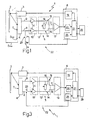
background elimination device 1 comprises an optoelectronic device for emission of light, in this case aphotoemitter 3, which can generate as output, in a pre-determined direction, and according to a control signal received as input, a light beam comprising a sequence of light pulses; and an optoelectronic reception device, in this case aphotoreceiver 4, which, via an optical triangulation system, can receive the light beam reflected by theobject 2, in order to supply as output a pair of electrical position signals, the values of which together have correlation with the distance of theobject 2 itself, measured relative to thebackground elimination device 1. - The
background elimination device 1 additionally comprises adifferential circuit 5, which is connected downstream from thephotoreceiver 4, and can process the pair of electrical position signals supplied by thephotoreceiver 4 itself, in order to supply as output a differential signal which has a value indicative of the distance of. theobject 2; and aprocessing device 6, which can receive the differential signal, and compare it with a pre-determined switching signal, in order to supply as output an information signal which has a first, or alternatively a second logic state, indicating respectively a condition of presence or absence of theobject 2 within the "field". - The
photoreceiver 4 is advantageously defined by a sensor of a known type, generally indicated by the abbreviation "PSD" (Position Sensitive Device), which has asurface 7 which is sensitive to the position of the incident light beam, and comprises a first andsecond output terminal - In detail, the
photoreceiver 4 can supply at the first andsecond terminals surface 7 of the light beam reflected by theobject 2. - In greater detail, the
photoreceiver 4 is positioned relative to thephotoemitter 3, such as to provide accurate optical triangulation of the light beam for emission and reception, thus defining a univocal ratio between the position of the point of incidence of the light beam on thesurface 7 of thephotoreceiver 4, and the distance of theobject 2 measured relative to thebackground elimination device 1. - This ratio thus provides a correlation between the distance of the
object 2 from thebackground elimination device 1, and the two values relative to the first and second position signals. - The
differential circuit 5 comprises anamplification stage 10, which is of a known type, and can be defined for example by a pair of amplification circuits 11 (illustrated schematically), which can receive as input respectively the first and the second position signal, in order to provide amplification of the latter as output; and aregulator stage 12, which is connected to thephotoreceiver 4 via theamplification stage 10, and can permit regulation of the "limit threshold". - The
differential circuit 5 additionally comprises adifferential stage 13, which is connected downstream from theregulator stage 12, from which it receives the first and the second position signal, and can supply as output the differential signal, which is determined by the amplification of the difference of potential present between the first and the second signal. - In other words, the
amplification stage 10 and theregulator stage 12 define a first and a second amplification "channel" 14, 15 with variable gain, which connect the input terminals of thedifferential stage 13 to the output terminals of thephotoreceiver 4, i.e. which connect the first andsecond output terminals photoreceiver 4, respectively to a first and asecond input terminal 16, 17 of thedifferential stage 13. - The
regulator stage 12 comprises a variable resistance resistor 18 (indicated schematically) of a known type, for example a manual regulation multi-revolution unit or a digital trimmer, by means of which it is possible to control the variation of the "limit threshold" in a known manner, by means of unbalancing of the amplification in the first andsecond amplification channels - At the first and
second terminals 16, 17, thedifferential stage 13 receives the first and second suitably unbalanced position signals of theregulator stage 12, and supplies theprocessing device 6 with the differential signal. - The
processing device 6 comprises asynchronisation unit 19, which can generate the control signal which controls the emission of the light pulses from thephotoemitter 3, and acomparison unit 20, which can receive the differential signal, and compare the latter with the switching threshold, such as to supply as output a detection signal, the logic state of which indicates the presence or absence of theobject 2 within the "field". - In detail, the
comparison unit 20 has a switching threshold which has a pre-determined reference voltage, which for example is zero, and, according to the voltage value of the differential signal, controls the transition of the detection signal from one logic state to the other. - The
processing device 6 additionally comprises acentral control unit 21, which can coordinate and control the operations carried out both by thecomparison unit 20, and by thesynchronisation unit 19. - In particular, the
central control unit 21 can receive the detection signal from thecomparison unit 20, in order to. supply as output the information signal which indicates the presence/absence of the object within the "field". - Preferably, but not necessarily, the
background elimination device 1 can be provided with aninterface unit 29, which cooperates with theprocessing device 6, and can permit variation of the resistance of theresistor 18. - The
interface unit 29 can advantageously be defined by a circuit of a known type, comprising a regulation push button and a display unit which can display the value of the "limit threshold". - The
background elimination device 1 is also provided with a preliminary search circuit, which can search for the presence/absence of an object at thebackground elimination device 1, before the latter carries out the detection of the arrangement of the object within the "field". - In particular, the preliminary search circuit is defined by a
sensing circuit 22, comprising aswitch 23, which is connected between thefirst output terminal 8 of thephotoreceiver 4, and aground terminal 24, which has a pre-determined potential VRF (for example a ground potential of VRF=0). - Finally, the
background elimination device 1 is provided with aselection unit 25, which cooperates with thecentral control unit 21, and can control selectively the opening/closure of theswitch 23, thus giving rise to selection of one of the following functioning modes of thebackground elimination device 1. - A "background elimination" functioning mode, in which the
background elimination device 1 can detect the presence/absence of anobject 2 within the pre-determined "field", i.e. which can detect the arrangement of theobject 2 itself, by measuring the distance, and comparing the latter with the limit threshold. - A "sensing" functioning mode, in which the
background elimination device 1 can carry out a preliminary search, in order to detect only the presence or absence of anobject 2, independently from the distance of the latter. - The functioning of the
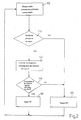
background elimination device 1 will now be described with reference tofigure 2 . - Let it be assumed that, initially, the "limit threshold" has been pre-determined by means of corresponding regulation of the
variable resistance resistor 18, and thebackground elimination device 1 is in the "background elimination" functioning mode. - Initially,
block 100 is reached, in which, via thephotoemitter 3, thecentral control unit 21 commands emission of a beam of light pulses; for the sake of descriptive simplicity, the emission of a sequence defined by a first and a second pulse is taken into consideration. - In
block 100, via theselection unit 25, thecentral control unit 21 commands closure of theswitch 23, thus giving rise to transition of thebackground elimination device 1 from the "background elimination" functioning mode to the "sensing" functioning mode, in which the preliminary search for theobject 2 is activated. -
Block 100 is followed byblock 110, in which the presence/absence of an object is verified. - In detail, in the "sensing" functioning mode, closure of the
switch 23 gives rise to "exclusion" of the first channel, i.e. to "setting" of the pre-determined potential VRF (for example zero), at the first position signal at thefirst input terminal 16 of thedifferential stage 13; in this condition, the functioning of thedifferential circuit 5 is limited to amplification of thesecond channel 15, since the differential signal output by thedifferential stage 13 corresponds to the difference between the value of the second signal, suitably amplified, and the pre-determined potential VRF. - Thus, if, for example, the potential VRF is set to zero, after an object has been detected, the
background elimination device 1 has the second signal, and thus the differential signal, with a value other than zero, whereas in the opposite case, i.e. in the absence of objects, the second signal, and thus the differential signal, have a value of zero. - By this means, by comparison between the differential signal and the switching threshold, the
comparison unit 20 can provide an indication of presence or absence of theobject 2. - In greater detail, the
central control unit 21 verifies the logic state of the detection signal. If the detection signal has the logic state which indicates the absence of objects, block 110 is followed byblock 120, in which, via the information signal, thecentral control unit 21 provides an indication of the absence of objects. - Preferably, but not necessarily, in this case, any subsequent analysis of the second pulse emitted by the
photoemitter 3 is prevented, since the lack of objects at any distance has been ascertained viablock 110. -
Block 120 is followed byblock 100, in which a new emission cycle, and thus new "sensing", is reiterated. - If the detection signal has the logic state which indicates the presence of an object, block 110 is followed by
block 130, in which, via theselection unit 25, thecentral control unit 21 commands opening of theswitch 23, and thus transition from the "sensing" functioning mode to the "background elimination" functioning mode. - In
block 130, thebackground elimination device 1 detects the second light pulse. - Opening of the
switch 23 makes it possible to determine the distance of theobject 2 from thebackground elimination device 1. -
Block 130 is followed byblock 140, in which it is verified whether theobject 2 detected is disposed within the "field". - In particular, after reception of the second light pulse (block 130), the
photoreceiver 4 supplies as input to thedifferential circuit 5 the first and second signals, which are amplified in the tworespective channels differential stage 13, which supplies the differential signal as output. - At this point (block 140), the
comparison unit 20 carries out the comparison between the differential signal and the switching threshold, supplying as output the detection signal by means of which thecentral control unit 21 is able to supply the information signal which indicates the absence or presence of theobject 2 in the "field". - In particular, if the
central control unit 21 verifies the presence of theobject 2 within the "field", block 140 is followed byblock 150, whereas otherwise, block 140 is followed byblock 120. -
Block 150 is followed byblock 100, in which a new detection cycle is reiterated. - On the basis of the foregoing description, it should be emphasised that the condition of "setting" the pre-determined potential VRF in the first channel, which gives rise to transition from the "background elimination" functioning mode to the "sensing" functioning mode, can be obtained by setting the pre-determined potential VRF at any point of the first amplification channel, i.e. by connecting the
switch 23 between any point of thefirst amplification channel 14 and the terminal 24. - In this case, for example, the
switch 23 can be connected between the terminal 24 and a connection point contained between theamplification stage 10 and theregulator stage 12, or between the terminal 24 and thefirst input terminal 16 of thedifferential stage 13. - On the basis of the foregoing description, it should also be emphasised that the transition from the "background elimination" functioning mode, to the "sensing" functioning mode, can be obtained by setting the pre-determined potential VRF at any point of the second amplification channel, i.e. by connecting the
switch 23 between any point of thesecond amplification channel 14 and the terminal 24. - In this case, the presence/absence of the object is detected by means of processing of the first signal, whereas the pre-determined potential VRF is set at the second signal, by means of the "exclusion" of the
second channel 15. - According to the variant illustrated in
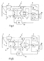
figure 3 , thebackground elimination device 1 has a circuit configuration in which theswitch 23 of thesensing circuit 22 has one terminal which is connected to an input of thedifferential circuit 5, and the opposite terminal which is connected to thefirst output terminal 8 of thephotoreceiver 4. - Similarly to the above-described functioning, via the
selection unit 25, thecentral control unit 21 commands closure/opening of theswitch 23, thus giving rise to transition of thebackground elimination device 1 from the "background elimination" functioning mode, to the "sensing" functioning mode. - In detail, in this case, opening of the
switch 23 gives rise to "setting" of a zero value (of current or voltage) in thefirst channel 14, and consequently, in this case also, similarly to the above-described functioning, to the amplification and processing of a differential signal which contains only the information concerning the presence/absence of an object supplied by thesecond channel 15. - On the basis of the foregoing description, it should be emphasised that the condition of "setting" a zero value (of current or voltage) in the
first channel 14, which gives rise to transition from the "background elimination" functioning mode to the "sensing" functioning mode, can be obtained by interrupting the passage of current at any point of the first amplification channel; consequently, theswitch 23 can be positioned at any point of thefirst amplification channel 14. - In this case, for example, the
switch 23 can be interposed between theamplification stage 10 and theregulator stage 12, or between thefirst input terminal 16 of thedifferential stage 13, and an output of theregulator stage 12. - As an alternative to the
first channel 14, theswitch 23 can be connected at any point of thesecond amplification channel 15, thus giving rise to the same functioning of thebackground elimination device 1. - It will be appreciated that in this case, a potential with a value of zero is set at the second signal, whereas only the first signal is amplified and processed, such as to detect the presence of the object.
- According to the variant illustrated in
figure 4 , thesensing circuit 22 of thebackground elimination device 1 does not have theswitch 23, and has anunbalance device 26, which can vary the amplification of thefirst channel 14 according to a control signal supplied by theselection unit 25. - In particular, similarly to the variants previously described, in which the "sensing" functioning mode is controlled by setting a pre-determined potential VRF, of, for example, zero, at any point of the
first amplification channel 14, this condition can be obtained, for example, by means of strong attenuation of the first signal, implemented by means of theunbalance device 26. - In this case also, the second signal is processed, whereas the first signal is excluded by setting a pre-determined potential VRF in the first channel.
- In this case, the attenuation can be obtained, for example, by means of regulation of the gain of one of the amplifiers 11 (illustrated schematically), which are present in the
amplification stage 10, or by means of corresponding regulation of thedifferential stage 13. - According to the variant illustrated in
figure 5 , in comparison with the variant illustrated infigure 4 , thesensing circuit 22 of thebackground elimination device 4 does not have either theunbalance device 26 or theselection unit 25, and is provided with a measuringunit 27, which can detect the value of the first signal present at theoutput terminal 8 of thephotoreceiver 4, in order to supply to the central control unit 21 a signal which indicates the presence/absence of an object. - In use, in the "sensing" functioning mode, via the measuring
device 27, thebackground elimination device 1 measures the value of the signal at thefirst terminal 8, and if the presence of the object is detected, it changes to the "background elimination" functioning mode. - In detail, if the value of the first signal is zero, the measuring
device 27 sends a signal which indicates the absence of anobject 2, to thecentral control unit 21, which supplies as output the information signal which indicates the absence of theobject 2 within the "field", whereas in the opposite case, i.e. if the value of the first signal is other than zero, the measuringdevice 27 sends a signal which indicates the presence of an object, to thecentral control unit 21, which commands transition of thebackground elimination device 1 to the "background elimination" functioning mode, in which, similarly to the above-described variants, it is verified whether theobject 2 is within or outside the "field". - On the basis of the foregoing description, it should be emphasised that the measuring
device 27 can detect the first signal at any point of thefirst amplification channel 14. - It should also be emphasised that, as an alternative to the detection of the first signal, the measuring
device 27 can detect the second signal at any point of thesecond amplification channel 15. - Finally, the measuring
device 27 can be connected to the first andsecond amplification channels - The
background elimination device 1 has the advantage that it is accurate, i.e. it can switch the information signal which indicates the presence/absence of the object within the "field", according to the distance of the object to be detected, and independently from the reflective power of the latter. - Finally, the
background elimination device 1 has the advantage that it is structurally simple and economical. - In particular, the
background elimination device 1 can make a direct comparison between the information obtained during the "background elimination" functioning mode, and during the "sensing" functioning mode. - In detail, the
background elimination device 1 can check that the items of information are compatible with one another; for example if they are in use, during the "background elimination" functioning mode and in the "sensing" functioning mode, there is detection respectively of the presence of an object or absence of an object within the "field", and thebackground elimination device 1 supplies as output the absence of the object within the "field", whereas if the information is compatible, thebackground elimination device 1 supplies as output the information signal obtained during the "background elimination" functioning mode. - Furthermore, the "sensing" functioning mode can precede or follow the "background elimination" functioning mode.
- In this case also, the comparison between the information obtained in the two functioning modes (and thus the indication of the presence/absence of the object within the "field") is carried out after the "sensing" and "background elimination" functioning modes.
Claims (17)
- Background elimination device (1) for detecting the presence of an object within a pre-determined interval of distances contained between the background elimination device (1) itself and a pre-determined limit threshold;
the background elimination device (1) comprises:- a photoemitter (3) which emits a beam of light pulses in a pre-determined direction;- a photoreceiver (4) which receives a beam of light pulses reflected by an object and supplies as output a pair of position signals which indicate the distance of the object (2) from the background elimination device (1); said photoreceiver (4) having a surface (7) which is sensitive to the position of the incident light beam and comprises a first and second output terminal (8,9) to provide for said position signals;- a pair of amplification channels (14, 15), which amplifies said position signals, and processing means (6) which receives said position signals from the photoreceiver (4) via the amplification channels (14, 15), and, according to the position signals supply as output a first information signal which indicates the arrangement of an object (2) within said pre-determined interval of distances;the background elimination device (1) being characterised in that it comprises:- preliminary search means (22) which process temporarily only one of the position signals in order to supply as output a second information signal which indicates only the presence/absence of an object (2) independently from the distance of the object (2) from the background elimination device (1); and- means for carrying out a comparison between the first and the second information signal, in order to verify the arrangement of the object within said pre-determined interval of distances . - Background elimination device according to claim 1, characterised in that said preliminary search means (22) comprise unbalance means (26) and selection means (25) which controls the unbalance means (26) in order to exclude temporarily one of said amplification channels (14, 15) and to set one of the said position signals to a pre-determined value (VRF); said processing means (6) being able to supply the second information signal, which indicates the presence/absence of an object (2), as output, by means of processing of the position signal present in the unaltered channel (15, 14).
- Background elimination device according to claim 1, characterised in that said preliminary search means (22) comprise switch means (23), and selection means (25) which can switch the said switch means (23), in order to exclude one of the said amplification channels temporarily (14, 15), and to set one of the said position signals to a pre-determined value (VRF); said processing means (6) being able to supply the second information signal which indicates the presence/absence of an object (2), as output, by means of processing of the position signal present in the included channel (15, 14).
- Background elimination device according to claim 3, characterised in that said selection means (25) command opening of one of the said amplification channels (14, 15) selectively, by switching of the said switch means (23) to exclude said amplification channel (14, 15) itself.
- Background elimination device according to claim 4, wherein said switch means (23) comprise a switch (23), which is connected between an output terminal (8) of the photoreceiver (4) and one of said amplification channels (14, 15).
- Background elimination device according to claim 3, characterised in that the said selection means (25) commands closure at a pre-determined potential (VRF) of one of the said amplification channels (14, 15), selectively, by switching of the said switch means (23) for excluding said amplification channel (14, 15).
- Background elimination device according to claim 6, wherein said switch means (23) comprise a switch (23), which is connected between a output terminal (8) of the photoreceiver (4) and a ground terminal (24) having a pre-determined potential (VRF).
- Background elimination device according to claim 3, wherein said selection means (25), controls selectively the opening/closure of the switch means (23), for selecting of one of the following functioning modes:a background elimination functioning mode, in which the background elimination device (1) detects the presence/absence of an object (2) within said pre-determined interval of distances; and a sensing functioning mode, in which the background elimination device (1) carry out a preliminary search, in order to detect only the presence/absence of an object (2), independently from the distance of the object from the background elimination device 1.
- Background elimination device according to claim 1, characterised in that the preliminary search means (22) comprise measurement means (27) which are connected to one of the amplification channels (14, 15), in order to measure the respective position signal; said measurement means (27) being able to process the position signal measured in order to supply to the said processing means (6) said second information signal which indicates the absence/presence of an object independently from the distance of the object (2) from the background elimination device.
- Method for detecting the presence/absence of an object within a pre-determined interval of distances comprising the following steps:- emitting by a photoemitter (3) a beam of light pulses in a pre-determined direction;- receiving by a photoreceiver (4) a beam of light reflected by an object, in order to supply as output a pair of position signals which indicate the distance of an object relative to a pre-determined point of reference; said photoreceiver (4) having a surface (7) which is sensitive to the position of the incident light beam and comprises a first and second output terminal (8, 9) to provide for said position signals;- processing (140) said position signals in order to supply as output a first information signal which indicates the arrangement of an object (2) within said pre-determined interval of distances;the method being characterised in that it comprises the following steps:- carrying out a preliminary search (110) for the object in which only one of the said position signals is processed in order to supply as output a second information signal, which indicates only the presence/absence of an object independently from the distance of the object (2) from said pre-determined point of reference; and- carrying out a comparison between the first and the second information signal, in order to verify the arrangement of the object within said pre-determined interval of distances.
- Method according to claims 10, characterised in that said preliminary search step (110) comprises the step of altering one of the said position signals in order to set it to a pre-determined value signal (VRF).
- Method according to claim 10 or 11, characterised in that said preliminary search step (110) comprises the step of opening by switching means (23) a output terminal 8 of the photoreceiver 4.
- Method according to claim 10 or 11, characterised in that said preliminary search step (110) comprises the step of connecting by switching means (23) a output terminal (8) of the photoreceiver (4) to a terminal (24) having a pre-determined potential (VRF).
- Method according to claim 10, characterised in that said preliminary search step (110) comprises the step of measuring one of said position signals.
- Method according to any one of claims 10 to 14, characterised in that said preliminary search step (110) precedes the step of processing (140) the position signals.
- Method according to any one of claims 10 to 15, characterised in that the said step of processing (140) the pair of position signals is carried out according to the indication of presence of the second information signal.
- Method according to claim 14, characterised in that, if said preliminary search step (110) detect that the object is present, said preliminary search step (110) is followed by said step of processing (140) the pair of position signals, in order to supply as output the first information signal which indicates the arrangement of an object (2) within said pre-determined interval of distances.
Applications Claiming Priority (2)
| Application Number | Priority Date | Filing Date | Title |
|---|---|---|---|
| ITBO000691 | 2000-11-24 | ||
| IT2000BO000691A ITBO20000691A1 (en) | 2000-11-24 | 2000-11-24 | METHOD AND DEVICE FOR THE DETECTION OF AN OBJECT WITH BACKGROUND REMOVAL |
Publications (2)
| Publication Number | Publication Date |
|---|---|
| EP1209487A1 EP1209487A1 (en) | 2002-05-29 |
| EP1209487B1 true EP1209487B1 (en) | 2010-10-27 |
Family
ID=11438881
Family Applications (1)
| Application Number | Title | Priority Date | Filing Date |
|---|---|---|---|
| EP01127862A Expired - Lifetime EP1209487B1 (en) | 2000-11-24 | 2001-11-22 | Method and device for detection of an object, with background elimination |
Country Status (4)
| Country | Link |
|---|---|
| EP (1) | EP1209487B1 (en) |
| AT (1) | ATE486292T1 (en) |
| DE (1) | DE60143341D1 (en) |
| IT (1) | ITBO20000691A1 (en) |
Families Citing this family (4)
| Publication number | Priority date | Publication date | Assignee | Title |
|---|---|---|---|---|
| DK1528411T3 (en) | 2003-10-27 | 2010-05-17 | Bea Sa | Distance measurement sensor |
| CN102679949A (en) * | 2012-05-17 | 2012-09-19 | 北京中远通科技有限公司 | Direct transmission type object detection system and method |
| ITUB20154173A1 (en) * | 2015-10-01 | 2017-04-01 | Datalogic IP Tech Srl | Optoelectronic sensor and operating method of an optoelectronic sensor |
| CN105372661A (en) * | 2015-10-15 | 2016-03-02 | 南昌航空大学 | Ultrasonic intelligent range finder |
Family Cites Families (3)
| Publication number | Priority date | Publication date | Assignee | Title |
|---|---|---|---|---|
| DE4040225C2 (en) * | 1990-12-15 | 1994-01-05 | Leuze Electronic Gmbh & Co | Diffuse sensors |
| DE4311691C2 (en) * | 1993-04-08 | 1996-07-04 | Sick Erwin Gmbh | Method for adjusting a light distance sensor and light distance sensor |
| DE4419032A1 (en) * | 1994-05-31 | 1996-01-25 | Sick Optik Elektronik Erwin | Diffuse sensors with background suppression, implemented using the quotient method |
-
2000
- 2000-11-24 IT IT2000BO000691A patent/ITBO20000691A1/en unknown
-
2001
- 2001-11-22 DE DE60143341T patent/DE60143341D1/en not_active Expired - Lifetime
- 2001-11-22 EP EP01127862A patent/EP1209487B1/en not_active Expired - Lifetime
- 2001-11-22 AT AT01127862T patent/ATE486292T1/en not_active IP Right Cessation
Also Published As
| Publication number | Publication date |
|---|---|
| DE60143341D1 (en) | 2010-12-09 |
| ATE486292T1 (en) | 2010-11-15 |
| EP1209487A1 (en) | 2002-05-29 |
| ITBO20000691A0 (en) | 2000-11-24 |
| ITBO20000691A1 (en) | 2002-05-24 |
Similar Documents
| Publication | Publication Date | Title |
|---|---|---|
| US6211784B1 (en) | Object detector and object detector system | |
| KR930002467B1 (en) | Device detecting something in a vehicle | |
| US6124936A (en) | Color discrimination system | |
| KR100622959B1 (en) | A separate type photoelectric switch | |
| EP0974208B1 (en) | Signal receiving circuit to receive signals transmitted from a probe | |
| JPH1123709A (en) | Distance-measuring device | |
| EP1209487B1 (en) | Method and device for detection of an object, with background elimination | |
| US5508645A (en) | Circuit for raising a minimum threshold of a signal detector | |
| JPH08201519A (en) | Light reception circuit | |
| US5986255A (en) | Photoelectric cell with lockable differential processing | |
| EP1209447B2 (en) | Light detector and light detecting IC therefor | |
| JPH07174666A (en) | Otdr for automatic setting of pulse width and gain | |
| EP1237011A1 (en) | Optoelectronic distance measurement device | |
| JP3076617B2 (en) | Method and apparatus for adjusting sensitivity of photoelectric switch | |
| JPH05325065A (en) | Photoelectric smoke sensor | |
| US7106422B2 (en) | Rangefinder and measuring method | |
| JP2743038B2 (en) | Underwater distance measuring device using laser light | |
| JPH0194236A (en) | Light pulse tester | |
| KR200144344Y1 (en) | Laser diode output control circuit of internal pipe inspection device | |
| CN116030746A (en) | Display terminal | |
| JP2545311B2 (en) | Underwater distance measuring device with laser light | |
| JP2002252368A (en) | Ic for photodetection, and photodetector using the ic | |
| JPH1194542A (en) | Range-finding module | |
| JPH0579945A (en) | Receiving device for optical communication | |
| JPH06117821A (en) | Optical measuring apparatus |
Legal Events
| Date | Code | Title | Description |
|---|---|---|---|
| PUAI | Public reference made under article 153(3) epc to a published international application that has entered the european phase |
Free format text: ORIGINAL CODE: 0009012 |
|
| AK | Designated contracting states |
Kind code of ref document: A1 Designated state(s): AT BE CH CY DE DK ES FI FR GB GR IE IT LI LU MC NL PT SE TR |
|
| AX | Request for extension of the european patent |
Free format text: AL;LT;LV;MK;RO;SI |
|
| 17P | Request for examination filed |
Effective date: 20021126 |
|
| AKX | Designation fees paid |
Designated state(s): AT BE CH CY DE DK ES FI FR GB GR IE IT LI LU MC NL PT SE TR |
|
| 17Q | First examination report despatched |
Effective date: 20070105 |
|
| GRAP | Despatch of communication of intention to grant a patent |
Free format text: ORIGINAL CODE: EPIDOSNIGR1 |
|
| GRAS | Grant fee paid |
Free format text: ORIGINAL CODE: EPIDOSNIGR3 |
|
| GRAA | (expected) grant |
Free format text: ORIGINAL CODE: 0009210 |
|
| RAP1 | Party data changed (applicant data changed or rights of an application transferred) |
Owner name: DATALOGIC AUTOMATION S.R.L. |
|
| AK | Designated contracting states |
Kind code of ref document: B1 Designated state(s): AT BE CH CY DE DK ES FI FR GB GR IE IT LI LU MC NL PT SE TR |
|
| REG | Reference to a national code |
Ref country code: GB Ref legal event code: FG4D |
|
| REG | Reference to a national code |
Ref country code: CH Ref legal event code: EP |
|
| REG | Reference to a national code |
Ref country code: IE Ref legal event code: FG4D |
|
| REF | Corresponds to: |
Ref document number: 60143341 Country of ref document: DE Date of ref document: 20101209 Kind code of ref document: P |
|
| REG | Reference to a national code |
Ref country code: NL Ref legal event code: VDEP Effective date: 20101027 |
|
| PG25 | Lapsed in a contracting state [announced via postgrant information from national office to epo] |
Ref country code: PT Free format text: LAPSE BECAUSE OF FAILURE TO SUBMIT A TRANSLATION OF THE DESCRIPTION OR TO PAY THE FEE WITHIN THE PRESCRIBED TIME-LIMIT Effective date: 20110228 Ref country code: SE Free format text: LAPSE BECAUSE OF FAILURE TO SUBMIT A TRANSLATION OF THE DESCRIPTION OR TO PAY THE FEE WITHIN THE PRESCRIBED TIME-LIMIT Effective date: 20101027 Ref country code: AT Free format text: LAPSE BECAUSE OF FAILURE TO SUBMIT A TRANSLATION OF THE DESCRIPTION OR TO PAY THE FEE WITHIN THE PRESCRIBED TIME-LIMIT Effective date: 20101027 Ref country code: NL Free format text: LAPSE BECAUSE OF FAILURE TO SUBMIT A TRANSLATION OF THE DESCRIPTION OR TO PAY THE FEE WITHIN THE PRESCRIBED TIME-LIMIT Effective date: 20101027 Ref country code: FI Free format text: LAPSE BECAUSE OF FAILURE TO SUBMIT A TRANSLATION OF THE DESCRIPTION OR TO PAY THE FEE WITHIN THE PRESCRIBED TIME-LIMIT Effective date: 20101027 |
|
| PG25 | Lapsed in a contracting state [announced via postgrant information from national office to epo] |
Ref country code: BE Free format text: LAPSE BECAUSE OF FAILURE TO SUBMIT A TRANSLATION OF THE DESCRIPTION OR TO PAY THE FEE WITHIN THE PRESCRIBED TIME-LIMIT Effective date: 20101027 Ref country code: GR Free format text: LAPSE BECAUSE OF FAILURE TO SUBMIT A TRANSLATION OF THE DESCRIPTION OR TO PAY THE FEE WITHIN THE PRESCRIBED TIME-LIMIT Effective date: 20110128 Ref country code: MC Free format text: LAPSE BECAUSE OF NON-PAYMENT OF DUE FEES Effective date: 20101130 |
|
| REG | Reference to a national code |
Ref country code: CH Ref legal event code: PL |
|
| PLBI | Opposition filed |
Free format text: ORIGINAL CODE: 0009260 |
|
| PG25 | Lapsed in a contracting state [announced via postgrant information from national office to epo] |
Ref country code: ES Free format text: LAPSE BECAUSE OF FAILURE TO SUBMIT A TRANSLATION OF THE DESCRIPTION OR TO PAY THE FEE WITHIN THE PRESCRIBED TIME-LIMIT Effective date: 20110207 Ref country code: LI Free format text: LAPSE BECAUSE OF NON-PAYMENT OF DUE FEES Effective date: 20101130 Ref country code: CH Free format text: LAPSE BECAUSE OF NON-PAYMENT OF DUE FEES Effective date: 20101130 |
|
| 26 | Opposition filed |
Opponent name: LEUZE ELECTRONIC GMBH + CO. KG Effective date: 20110714 |
|
| PLAX | Notice of opposition and request to file observation + time limit sent |
Free format text: ORIGINAL CODE: EPIDOSNOBS2 |
|
| PG25 | Lapsed in a contracting state [announced via postgrant information from national office to epo] |
Ref country code: DK Free format text: LAPSE BECAUSE OF FAILURE TO SUBMIT A TRANSLATION OF THE DESCRIPTION OR TO PAY THE FEE WITHIN THE PRESCRIBED TIME-LIMIT Effective date: 20101027 |
|
| GBPC | Gb: european patent ceased through non-payment of renewal fee |
Effective date: 20110127 |
|
| PLAF | Information modified related to communication of a notice of opposition and request to file observations + time limit |
Free format text: ORIGINAL CODE: EPIDOSCOBS2 |
|
| REG | Reference to a national code |
Ref country code: DE Ref legal event code: R026 Ref document number: 60143341 Country of ref document: DE Effective date: 20110714 |
|
| PG25 | Lapsed in a contracting state [announced via postgrant information from national office to epo] |
Ref country code: IE Free format text: LAPSE BECAUSE OF NON-PAYMENT OF DUE FEES Effective date: 20101122 |
|
| PG25 | Lapsed in a contracting state [announced via postgrant information from national office to epo] |
Ref country code: GB Free format text: LAPSE BECAUSE OF NON-PAYMENT OF DUE FEES Effective date: 20110127 |
|
| REG | Reference to a national code |
Ref country code: FR Ref legal event code: ST Effective date: 20111125 |
|
| PG25 | Lapsed in a contracting state [announced via postgrant information from national office to epo] |
Ref country code: FR Free format text: LAPSE BECAUSE OF NON-PAYMENT OF DUE FEES Effective date: 20101227 |
|
| PLBB | Reply of patent proprietor to notice(s) of opposition received |
Free format text: ORIGINAL CODE: EPIDOSNOBS3 |
|
| PG25 | Lapsed in a contracting state [announced via postgrant information from national office to epo] |
Ref country code: CY Free format text: LAPSE BECAUSE OF FAILURE TO SUBMIT A TRANSLATION OF THE DESCRIPTION OR TO PAY THE FEE WITHIN THE PRESCRIBED TIME-LIMIT Effective date: 20101027 |
|
| PG25 | Lapsed in a contracting state [announced via postgrant information from national office to epo] |
Ref country code: LU Free format text: LAPSE BECAUSE OF NON-PAYMENT OF DUE FEES Effective date: 20101122 |
|
| PG25 | Lapsed in a contracting state [announced via postgrant information from national office to epo] |
Ref country code: TR Free format text: LAPSE BECAUSE OF FAILURE TO SUBMIT A TRANSLATION OF THE DESCRIPTION OR TO PAY THE FEE WITHIN THE PRESCRIBED TIME-LIMIT Effective date: 20101027 |
|
| PLCK | Communication despatched that opposition was rejected |
Free format text: ORIGINAL CODE: EPIDOSNREJ1 |
|
| APBM | Appeal reference recorded |
Free format text: ORIGINAL CODE: EPIDOSNREFNO |
|
| APBP | Date of receipt of notice of appeal recorded |
Free format text: ORIGINAL CODE: EPIDOSNNOA2O |
|
| APAH | Appeal reference modified |
Free format text: ORIGINAL CODE: EPIDOSCREFNO |
|
| REG | Reference to a national code |
Ref country code: DE Ref legal event code: R100 Ref document number: 60143341 Country of ref document: DE |
|
| APBU | Appeal procedure closed |
Free format text: ORIGINAL CODE: EPIDOSNNOA9O |
|
| PLBN | Opposition rejected |
Free format text: ORIGINAL CODE: 0009273 |
|
| STAA | Information on the status of an ep patent application or granted ep patent |
Free format text: STATUS: OPPOSITION REJECTED |
|
| 27O | Opposition rejected |
Effective date: 20200110 |
|
| PGFP | Annual fee paid to national office [announced via postgrant information from national office to epo] |
Ref country code: IT Payment date: 20201124 Year of fee payment: 20 Ref country code: DE Payment date: 20201119 Year of fee payment: 20 |
|
| REG | Reference to a national code |
Ref country code: DE Ref legal event code: R071 Ref document number: 60143341 Country of ref document: DE |