EP1206396B1 - Plastic closure with anti-backoff teeth on its threads - Google Patents
Plastic closure with anti-backoff teeth on its threads Download PDFInfo
- Publication number
- EP1206396B1 EP1206396B1 EP00969003A EP00969003A EP1206396B1 EP 1206396 B1 EP1206396 B1 EP 1206396B1 EP 00969003 A EP00969003 A EP 00969003A EP 00969003 A EP00969003 A EP 00969003A EP 1206396 B1 EP1206396 B1 EP 1206396B1
- Authority
- EP
- European Patent Office
- Prior art keywords
- closure
- projection means
- package according
- thread
- projection
- Prior art date
- Legal status (The legal status is an assumption and is not a legal conclusion. Google has not performed a legal analysis and makes no representation as to the accuracy of the status listed.)
- Expired - Lifetime
Links
- 239000004033 plastic Substances 0.000 title description 11
- 230000015572 biosynthetic process Effects 0.000 claims description 70
- 238000005755 formation reaction Methods 0.000 description 57
- 230000002401 inhibitory effect Effects 0.000 description 27
- 238000013022 venting Methods 0.000 description 6
- 238000007789 sealing Methods 0.000 description 5
- 230000013011 mating Effects 0.000 description 4
- 238000000465 moulding Methods 0.000 description 3
- 238000000034 method Methods 0.000 description 2
- 230000008569 process Effects 0.000 description 2
- 230000009467 reduction Effects 0.000 description 2
- 230000009471 action Effects 0.000 description 1
- 235000014171 carbonated beverage Nutrition 0.000 description 1
- 230000008859 change Effects 0.000 description 1
- 239000002131 composite material Substances 0.000 description 1
- 238000000748 compression moulding Methods 0.000 description 1
- 238000010276 construction Methods 0.000 description 1
- 230000000694 effects Effects 0.000 description 1
- 230000003993 interaction Effects 0.000 description 1
- 230000002452 interceptive effect Effects 0.000 description 1
- 239000000463 material Substances 0.000 description 1
- 238000012986 modification Methods 0.000 description 1
- 230000004048 modification Effects 0.000 description 1
- 239000002991 molded plastic Substances 0.000 description 1
- 238000005381 potential energy Methods 0.000 description 1
Images

Classifications
-
- B—PERFORMING OPERATIONS; TRANSPORTING
- B65—CONVEYING; PACKING; STORING; HANDLING THIN OR FILAMENTARY MATERIAL
- B65D—CONTAINERS FOR STORAGE OR TRANSPORT OF ARTICLES OR MATERIALS, e.g. BAGS, BARRELS, BOTTLES, BOXES, CANS, CARTONS, CRATES, DRUMS, JARS, TANKS, HOPPERS, FORWARDING CONTAINERS; ACCESSORIES, CLOSURES, OR FITTINGS THEREFOR; PACKAGING ELEMENTS; PACKAGES
- B65D51/00—Closures not otherwise provided for
- B65D51/16—Closures not otherwise provided for with means for venting air or gas
- B65D51/1672—Closures not otherwise provided for with means for venting air or gas whereby venting occurs by manual actuation of the closure or other element
- B65D51/1688—Venting occurring during initial closing or opening of the container, by means of a passage for the escape of gas between the closure and the lip of the container mouth, e.g. interrupted threads
-
- B—PERFORMING OPERATIONS; TRANSPORTING
- B65—CONVEYING; PACKING; STORING; HANDLING THIN OR FILAMENTARY MATERIAL
- B65D—CONTAINERS FOR STORAGE OR TRANSPORT OF ARTICLES OR MATERIALS, e.g. BAGS, BARRELS, BOTTLES, BOXES, CANS, CARTONS, CRATES, DRUMS, JARS, TANKS, HOPPERS, FORWARDING CONTAINERS; ACCESSORIES, CLOSURES, OR FITTINGS THEREFOR; PACKAGING ELEMENTS; PACKAGES
- B65D41/00—Caps, e.g. crown caps or crown seals, i.e. members having parts arranged for engagement with the external periphery of a neck or wall defining a pouring opening or discharge aperture; Protective cap-like covers for closure members, e.g. decorative covers of metal foil or paper
- B65D41/02—Caps or cap-like covers without lines of weakness, tearing strips, tags, or like opening or removal devices
- B65D41/04—Threaded or like caps or cap-like covers secured by rotation
- B65D41/0471—Threaded or like caps or cap-like covers secured by rotation with means for positioning the cap on the container, or for limiting the movement of the cap, or for preventing accidental loosening of the cap
-
- B—PERFORMING OPERATIONS; TRANSPORTING
- B65—CONVEYING; PACKING; STORING; HANDLING THIN OR FILAMENTARY MATERIAL
- B65D—CONTAINERS FOR STORAGE OR TRANSPORT OF ARTICLES OR MATERIALS, e.g. BAGS, BARRELS, BOTTLES, BOXES, CANS, CARTONS, CRATES, DRUMS, JARS, TANKS, HOPPERS, FORWARDING CONTAINERS; ACCESSORIES, CLOSURES, OR FITTINGS THEREFOR; PACKAGING ELEMENTS; PACKAGES
- B65D41/00—Caps, e.g. crown caps or crown seals, i.e. members having parts arranged for engagement with the external periphery of a neck or wall defining a pouring opening or discharge aperture; Protective cap-like covers for closure members, e.g. decorative covers of metal foil or paper
- B65D41/32—Caps or cap-like covers with lines of weakness, tearing-strips, tags, or like opening or removal devices, e.g. to facilitate formation of pouring openings
- B65D41/34—Threaded or like caps or cap-like covers provided with tamper elements formed in, or attached to, the closure skirt
- B65D41/3423—Threaded or like caps or cap-like covers provided with tamper elements formed in, or attached to, the closure skirt with flexible tabs, or elements rotated from a non-engaging to an engaging position, formed on the tamper element or in the closure skirt
Definitions
- the present invention relates generally to threaded plastic closures for containers, and more particularly to a threaded plastic closure for a container having one or more rotation-inhibiting projections which act in cooperation with vent grooves of an associated container to facilitate release of gas pressure from within the container during closure removal.
- Closures of this nature typically include a molded plastic closure cap having a top wall portion, and a depending cylindrical skirt portion.
- the skirt portion includes an internal thread formation configured for threaded cooperation with a like thread formation on an associated container.
- the desired sealing with the container can be achieved by providing the closure with a sealing liner positioned generally adjacent the top wall portion.
- closures of the above type have proven to be very commercially successful for use on containers having carbonated contents.
- closures of this type are typically configured to facilitate venting and release of gas pressure from within the container during closure removal.
- vent grooves in the container which grooves are generally axially oriented, and traverse and substantially interrupt the container thread formation.
- the threads of a closure can be interrupted to provide increased gas flow, with the provision of axially extending vent grooves in the side wall of closures also known.
- Molten plastic material naturally tends to seek the flow path of least resistance as the mold space is filled during the closure molding process.
- areas in which the closure wall thickness is reduced (i.e., at closure vent passages) which are bordered by areas of increased wall thickness may not fill as quickly as the thicker adjacent regions.
- the resulting knit/weld lines formed axially in the region of the vent passages naturally exhibit reduced strength, and can undesirably detract from the impact resistance of such closures.
- rotation-inhibiting projections are known, their use can also complicate closure application.
- the engagement of such a projection with the associated container thread during high-speed application can also undesirably result in "cocking" of closures, thus detracting from efficient high-speed bottling.
- the present invention is directed to a closure having an improved arrangement of rotation-inhibiting projections which facilitate release of gas pressure within an associated container prior to disengagement of the cooperating closure and container thread formations.
- the present closure includes a closure cap including a top wall portion, and a cylindrical skirt portion depending from the top wall portion.
- the cylindrical skirt portion includes an internal thread formation extending circumferentially of the closure at least 360°.
- the thread formation extends circumferentially of the closure more than 360°, to thereby at least partially overlap itself.
- the thread formation includes a thread start at an end thereof spaced furthest from the top wall portion of the closure cap. The thread start is that portion of the thread first moved into engagement with the thread formation of an associated container during high-speed application.
- the present closure includes at least one, and preferably a plurality, of rotation-inhibiting projections provided on the inside surface of the skirt portion adjacent the thread formation for engagement with a mating thread formation on the associated container.
- a rotation-inhibiting projection is positioned adjacent the thread formation in circumferentially spaced relationship to the thread start.
- the projection is asymmetrically configured relative to a radius of the closure through the projection.
- the projection defines a guide surface oriented in a direction of the thread formation toward the thread start, and an interference surface oriented in a direction of the thread formation away from the thread start.
- the interference surface of the projection is oriented at an angle between about 0° and 45° relative to the radius of the closure extending through the projection.
- the guide surface is oriented at an angle between about 70° and 90° relative to the radius through the projection, and thus provides a tapered "ramp surface" to facilitate high-speed application by smoothly engaging the container thread.
- the interference surface defines a more abrupt surface for engagement with the associated container during closure removal.
- the interference surface of each projection interferingly engage the axial vent grooves of the container during closure removal where the grooves traverse the container thread formation. A ratchet-like action is thus created as the closure is removed from the container, with each rotation-inhibiting projection sequentially engaging the vent grooves of the associated container.
- the rotation-inhibiting projection positioned closest to the thread start of the closure thread formation be spaced from the thread start between about 20° and 40° relative to the circumference of the closure.
- spacing between the projections is selected to optimize thread performance.
- the one of the rotation-inhibiting projections positioned along the extent of the thread formation closest to the thread start comprises a primary projection.
- further ones of the rotation inhibiting-projections are provided in the form of at least one secondary projection.
- At least one or more secondary projection is positioned symmetrically with respect to a portion of the closure diametrically opposite of the primary projection, with the preferred embodiment including a single secondary projection positioned diametrically opposite of, and thus in symmetry with, the primary projection of the closure.
- such secondary projections are positioned symmetrically with respect to the portion of the closure diametrically opposite of the primary projection.
- each of the secondary projections is positioned between about 20° and 40° relative to the portion of the closure diametrically opposite the primary projection.
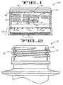
- FIGURE 1 With reference to FIGURE 1, therein is illustrated a plastic closure 10 having rotation-inhibiting projections embodying the principles of the present invention.
- This type of closure sometimes referred to as a "composite closure" by virtue of its formation with an outer shell or cap, and an inner sealing liner, has proven to be very well-suited for use on containers having carbonated or otherwise pressurized contents to form a package therewith.
- Closure 10 includes an outer molded closure cap or shell 12 having a top wall portion 14, and a depending cylindrical skirt portion 16.
- the skirt portion 16 includes an internal, helical thread formation 18.
- thread formation 18 is shown in a discontinuous configuration, comprising plural thread segments, with the thread formation traversed by generally axially extending vent grooves or passages 20. Vent grooves 20 facilitate release of gas pressure from within a container during removal of the closure therefrom, with release and equalization of gas pressure preferably effected prior to disengagement of thread formation 18 from the cooperating thread formation of the associated container.
- Thread formation 18 preferably extends about the closure at least 360°, and preferably more than 360° so that the thread formation overlaps itself. Typically, thread formation 18 extends approximately 540° about the interior of the skirt portion 16 and thus, the thread formation overlaps itself along approximately one-half of the extent of the thread formation.
- thread start designated 19, the portion of the thread formation 18 which is first moved into engagement with the threads in an associated container during application of the closure.
- the thread start is the portion of the thread formation 18 positioned furthest from top wall portion 14.
- the closure 10 is configured for tamper-indication, and to this end, includes an annular pilfer band 22 depending from skirt portion 16.
- the pilfer band 22 includes a plurality of circumferentially spaced, inwardly-extending flexible projections 24 which are configured for cooperative interengagement with the associated container.
- the pilfer band 22 is distinguished from the skirt portion 16 by a score line 26 which extends partially or completely about the closure cap.
- the pilfer band 22 is at least partially detachably connected to the skirt portion 16 by the provision of a plurality of circumferentially spaced frangible ribs 28 which extend between the inside surfaces of the skirt portion 16 and the pilfer band, generally spanning the score line 26.
- the interaction of projections 24 with an associated container during closure removal acts to fracture the frangible ribs 28, thus partially or completely separating the pilfer band 22 from the skirt portion 16. Readily visually discernable evidence of opening is thus provided.
- the closure 10 includes a sealing liner 30 positioned adjacent the inside surface of the top wall portion 14.
- An annular lip or shoulder 32 extends generally inwardly from the skirt portion 16 to facilitate formation of the liner 30 within the closure cap by compression molding.
- the present closure is configured to facilitate venting and release of gas pressure from within an associated container, particularly a container having carbonated contents of the like.
- a container of this nature is configured in accordance with the illustrated container C, shown in FIGURE 2, including a threaded neck portion including a thread formation T configured to mate with the thread formation 18 of the closure 10.
- the neck portion of the container includes at least one, and typically a plurality (i.e., four) of axially extending vent grooves G formed in the neck portion of the container, traversing the container thread formation T.
- vent grooves facilitate release of gas pressure from within the container during closure removal by providing a plurality of flow paths which extend from the region of the sealing liner 30 of the closure downwardly to the lower free edge of the closure pilfer band.
- the vent grooves G are formed to extend into the container neck such that the grooves G are positioned inwardly of the thread formation 18 of the closure when the closure is positioned on the container.
- closure 10 includes a plurality of rotation-inhibiting projections configured for cooperative, interengagement with the vent grooves G of the associated container C.
- the provision of these projections facilitates venting and release of gas pressure from within the container C during closure removal, prior to disengagement of closure thread 18 from container thread T.
- the configuration and placement of the rotation-inhibiting projections have been specifically selected to provide the desired cooperation with the vent grooves G, while at the same time facilitating closure application and providing desired closure performance.
- the object of providing one or more rotation-inhibiting projections is to increase frictional drag between the closure 10 and the associated container C by creating radial interference between each of the projections and the vent grooves G of the container, in addition to the radial interference created with the container thread formation.
- the creation of this frictional drag helps to dissipate potential energy stored in the bottle head space during closure removal.
- the frictional dissipation of energy acts to limit the amount of head space energy converted to closure kinetic energy during opening.
- each of the rotation-inhibiting projections of the present invention is configured to not only include an interference surface, but also a guide surface which facilitates closure application.
- each projection is asymmetrically configured, relative to a radius extending through the respective projection.
- FIGURES 1, 3, and 4 A presently preferred configuration of the present rotation-inhibiting projections is shown in FIGURES 1, 3, and 4.
- the rotation inhibiting projection is designated 40, and for purposes of the present discussion, will be considered a primary projection.
- Projection 40 is primary in the sense that it is positioned in most closely spaced relation to the thread start 19 of the closure thread 18, and thus is the first of the projections 40 to engage the associated container thread during application, and the last to disengage the container thread during closure removal. It will be observed that the closure is configured such that no interference projection or the like will come into engagement with the container thread formation T, during closure application, prior to engagement of the container thread with the projection 40.
- the projection 40 includes a guide surface 42, an interference surface 44, and an intermediate surface 46 positioned between the guide and interference surfaces.
- the primary projection 40 is positioned between about 20° and 40° from the thread start 19, relative to the circumference of the closure. In a presently preferred embodiment, the primary projection 40 is positioned about 30° from the thread start. This arrangement assures engagement of the mating thread formations prior to engagement of the projection 40 with the container thread T.
- the interference surface 44 is oriented in a direction of the thread formation away from the thread start 19.
- the interference surface is oriented at an angle between about 0° and 45° relative to a radius of the closure, through the projection, with the interference surface 44 more preferably oriented at an angle between about 25° and 35° relative to the radius.
- the surface 44 is oriented 30° in the illustrated embodiment, and thus presents an abrupt change in the radial elevation of the projection.
- each of the projections 40 is asymmetrically configured relative to a radius of the closure therethrough, with the guide surface 42 being oriented at an angle relative to a radius through the projection greater than an angle at which the interference surface 44 is oriented.
- each of the guide surface 42, interference surface 44, and intermediate surface 46 are generally planar, but it will be understood that it is within the purview of the present invention to provide one or more rotation-inhibiting projections which are otherwise configured while keeping with the teachings disclosed herein.
- each of the projections 40 has a radial dimension less than the height of the thread formation 18, with each projection having a typical radial dimension between about 0.51 mm and 1.02 mm (0.020 inches and 0.040 inches). With this relative dimensioning, the intermediate surface 46 has a circumferential dimension of approximately 1.52 mm (0.060 inches). While it will be understood that the specific dimensions of the projections can be varied while keeping with the principles disclosed herein, the illustrated embodiment of the projections has been found to provide the desired friction-increasing interference, while facilitating high-speed application of the closures to containers.
- the closure 10 includes at least one secondary projection, designated 40'.
- the one or more secondary projections 40' are preferably configured in accordance with the above description of primary projection 40, with each of the secondary projections preferably being asymmetrical with respect to a respective closure radius extending therethrough, with each including a guide surface, an interference surface, and an intermediate surface therebetween.
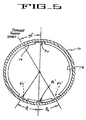
- FIGURE 5 illustrates the presently preferred configuration of a closure having rotation-inhibiting projections embodying the present invention.
- the internal thread formation 18 extends circumferentially of the closure at least 360°, and typically extends more than 360° to thereby at least partially overlap itself.
- the thread formation 18 extends 540°, and thus, overlaps itself throughout approximately 180°, thus presenting a portion within the thread formation which is a "double thread".
- the primary projection 40 be positioned between overlapping portions of the thread formation 18, with FIGURE 5 illustrating spacing of the primary projection 40 30° from the thread start 19 of the thread formation.
- FIGURE 5 illustrates the provision of at least one secondary projection 40'. It is presently preferred that a single projection 40' be positioned symmetrically with respect to a portion of the closure cap 12 diametrically opposite of the primary projection 40, as illustrated in FIGURE 5. Positioning the rotation-inhibiting projections 40, 40' in symmetrical or centered relationship about the rotational axis of the closure desirably tends to maintain the thread formation 18 in engagement with the container throughout the circumference of the closure. In an alternate embodiment, a pair of secondary projections 40' are positioned symmetrically with respect to the diametrically opposite portion of the closure.
- each of a pair of secondary projections 40' is positioned at a respective angle ⁇ 1 , ⁇ 2 with respect to the portion of the closure skirt 16 diametrically opposite of the primary projection 40.
- each of the secondary projections 40' is positioned about 30° relative to the diametrically opposite portion of the closure, that is, each of ⁇ 1 , and ⁇ 2 equals 30°. This arrangement maintains a general symmetry between the primary projection 40 and the secondary projections 40', thus facilitating alignment of the closure with the associated container.
- the present closure includes a primary projection 40 spaced between about 20° to 40° from the thread start 19, and at least one secondary projection 40' spaced between about 180° and 240° from the thread start, with the single secondary projection 40' of the illustrated embodiment positioned diametrically opposite of primary projection 40.
- the closure may further include at least one further secondary projection 40' preferably spaced no further than about 250° from the thread start, with the plural secondary projections 40' positioned symmetrically relative to the portion of the closure diametrically opposite of primary projection 40.
- rotation-inhibiting projections 40, 40' in accordance with the present invention has been found to desirably facilitate release of gas pressure from within the associated container, which affords greater flexibility in closure design. While previous constructions have included a plurality of the vent grooves or passages 20 in the closure cap, it is desirable to increase the length and strength of individual thread segments of the thread formation, thus suggesting the desirability of minimizing the number of vent passages, while also minimizing their size to maximize the size of thread segments. It is believed that frictional drag created by the projections 40, 40' can be sufficient to provide proper gas venting, as the projections "catch" the container vent grooves and allow more time for gas venting.
- vent passages or passages 20 It is also believed to be desirable to reduce the depth of vent grooves or passages 20, which is also possible by the provision of the rotation-inhibiting projections 40, 40'.
- vent passages it is desirable that such passages not be configured to extend into the skirt portion 16 of the closure, i.e., not extend outwardly of the root diameter of the thread formation 18. Reducing the depth of such vent grooves is desirable in that it facilitates high-speed closure molding. Areas in which the closure wall thickness is reduced, by the provision of relatively deep vent passages, will not fill as quickly with molten plastic as adjacent, relatively thicker areas. The resulting knit/weld lines formed axially in the vent locations will naturally have reduced strength, and significantly contribute to typical closure impact failures. Again, the reduction in the depth of vent passages can be achieved by the provision of rotation-inhibiting projections in accordance with the present invention.
Landscapes
- Engineering & Computer Science (AREA)
- Mechanical Engineering (AREA)
- Closures For Containers (AREA)
- Containers And Packaging Bodies Having A Special Means To Remove Contents (AREA)
Applications Claiming Priority (3)
| Application Number | Priority Date | Filing Date | Title |
|---|---|---|---|
| US384824 | 1999-08-27 | ||
| US09/384,824 US6123212A (en) | 1999-08-27 | 1999-08-27 | Plastic closure with rotation-inhibiting projections |
| PCT/US2000/040695 WO2001015988A1 (en) | 1999-08-27 | 2000-08-21 | Plastic closure with anti-backoff teeth on its threads |
Publications (2)
| Publication Number | Publication Date |
|---|---|
| EP1206396A1 EP1206396A1 (en) | 2002-05-22 |
| EP1206396B1 true EP1206396B1 (en) | 2005-08-03 |
Family
ID=23518913
Family Applications (1)
| Application Number | Title | Priority Date | Filing Date |
|---|---|---|---|
| EP00969003A Expired - Lifetime EP1206396B1 (en) | 1999-08-27 | 2000-08-21 | Plastic closure with anti-backoff teeth on its threads |
Country Status (18)
| Country | Link |
|---|---|
| US (1) | US6123212A (enExample) |
| EP (1) | EP1206396B1 (enExample) |
| JP (1) | JP4017393B2 (enExample) |
| CN (1) | CN1166533C (enExample) |
| AR (1) | AR040619A1 (enExample) |
| AU (1) | AU761701B2 (enExample) |
| BR (1) | BR0012967A (enExample) |
| CA (1) | CA2379574C (enExample) |
| CO (1) | CO5280106A1 (enExample) |
| DE (1) | DE60021731T2 (enExample) |
| ES (1) | ES2246899T3 (enExample) |
| GC (1) | GC0000139A (enExample) |
| HU (1) | HU229413B1 (enExample) |
| MX (1) | MXPA02001135A (enExample) |
| PL (1) | PL202734B1 (enExample) |
| TW (1) | TW585821B (enExample) |
| WO (1) | WO2001015988A1 (enExample) |
| ZA (1) | ZA200200277B (enExample) |
Cited By (4)
| Publication number | Priority date | Publication date | Assignee | Title |
|---|---|---|---|---|
| USD633386S1 (en) | 2010-05-27 | 2011-03-01 | Silgan White Cap LLC | Closure |
| USD634199S1 (en) | 2010-05-27 | 2011-03-15 | Silgan White Cap LLC | Closure |
| USD634200S1 (en) | 2010-05-27 | 2011-03-15 | Silgan White Cap LLC | Closure |
| US8231020B2 (en) | 2010-05-27 | 2012-07-31 | Silgan White Cap LLC | Impact resistant closure |
Families Citing this family (90)
| Publication number | Priority date | Publication date | Assignee | Title |
|---|---|---|---|---|
| FR2802513B1 (fr) * | 1999-12-16 | 2002-02-15 | Valois Sa | Reservoir et distributeur de produit fluide a securite de devissage |
| US6381928B1 (en) | 2000-05-26 | 2002-05-07 | Owens-Illinois Closure Inc. | Tamper-indicating closure and container package |
| FR2813280B1 (fr) * | 2000-08-23 | 2003-02-21 | Rical Sa | Col de recipient comportant un filetage externe et une saillie de freinage du vissage d'un bouchon |
| FR2828176A1 (fr) * | 2001-08-01 | 2003-02-07 | Rical Sa | Bouchon et col de recipient empechant l'auto-devissage du bouchon sous l'effet de la pression interne au recipient |
| US6659297B2 (en) * | 2001-11-28 | 2003-12-09 | Owens-Illinois Closure Inc. | Tamper-indicating closure, container, package and methods of manufacture |
| US7168581B2 (en) | 2001-12-21 | 2007-01-30 | Rexam Medical Packaging Inc. | Closure for a retort processed container having a peelable seal |
| CZ2002176A3 (en) | 2002-01-16 | 2004-04-14 | Natalia Ing. Larionova | Screw -cap closure for a container's mouth and manufacture method |
| US6889857B2 (en) * | 2002-02-01 | 2005-05-10 | Rexam Medical Packaging Inc. | Sealing arrangement for a closure for a fitment |
| US6913157B2 (en) * | 2002-02-26 | 2005-07-05 | Delta Plastics, Inc. | Closure and container and combination thereof with anti-backoff member |
| US20040237379A1 (en) * | 2003-05-28 | 2004-12-02 | Long Roger H. | Insect traps |
| US7644902B1 (en) | 2003-05-31 | 2010-01-12 | Rexam Medical Packaging Inc. | Apparatus for producing a retort thermal processed container with a peelable seal |
| US7048140B1 (en) * | 2003-12-12 | 2006-05-23 | Brunswick Corporation | Vented liquid containment device |
| JP4608921B2 (ja) * | 2004-03-22 | 2011-01-12 | ソニー株式会社 | 表示装置の製造方法および表示装置 |
| US7523839B2 (en) * | 2004-04-08 | 2009-04-28 | The Glad Products Company | Ventable spin lock container |
| US7798359B1 (en) | 2004-08-17 | 2010-09-21 | Momar Industries LLC | Heat-sealed, peelable lidding membrane for retort packaging |
| US7703617B1 (en) * | 2004-11-19 | 2010-04-27 | Rexam Closures And Containers, Inc. | Bayonet closure container combination with angled bayonet lugs |
| US7575123B2 (en) * | 2005-01-19 | 2009-08-18 | Rieke Corporation | Tamper-evident locking band for a container closure |
| US7780024B1 (en) | 2005-07-14 | 2010-08-24 | Rexam Closures And Containers Inc. | Self peel flick-it seal for an opening in a container neck |
| US8100277B1 (en) | 2005-07-14 | 2012-01-24 | Rexam Closures And Containers Inc. | Peelable seal for an opening in a container neck |
| FR2891533B1 (fr) * | 2005-10-04 | 2007-12-07 | Valois Sas | Organe de recouvrement, procede de fabrication d'un tel organe et distributeur de produit fluide utilisant un tel organe. |
| FR2891530B1 (fr) | 2005-10-04 | 2007-12-07 | Valois Sas | Organe de recouvrement, procede de fabrication d'un tel organe et distributeur de produit fluide utlisant un tel organe. |
| ES2302170T3 (es) * | 2005-12-01 | 2008-07-01 | TETRA LAVAL HOLDINGS & FINANCE SA | Metodo para producir partes superiores de plastico para recipientes sellados de productos alimenticios que se pueden verter, y partes superiores de plastico para recipientes, asi producidas. |
| ITMO20060027A1 (it) * | 2006-01-27 | 2007-07-28 | Sacmi | Mezzi di chiusura |
| US7886928B2 (en) * | 2006-04-28 | 2011-02-15 | Silgan Plastics Corporation | Container with venting closure assembly |
| US7891510B2 (en) | 2006-12-26 | 2011-02-22 | Abbott Laboratories | Container closure assembly |
| WO2008131199A1 (en) * | 2007-04-19 | 2008-10-30 | Closure Systems International, Inc. | Package with closure having rotation-inhibiting projections |
| US8584876B2 (en) * | 2007-07-05 | 2013-11-19 | Kraft Foods Group Brands Llc | Food containers adapted for accommodating pressure changes using skip seals and methods of manufacture |
| US7832595B2 (en) * | 2007-07-23 | 2010-11-16 | Conopco, Inc. | Household liquid dispenser with keyed spout fitment and refill |
| US20090045158A1 (en) * | 2007-08-14 | 2009-02-19 | Alcoa Closure Systems International, Inc. | Threaded closure with internal ribs |
| JP4251334B2 (ja) * | 2007-08-22 | 2009-04-08 | 日本臓器製薬株式会社 | 包装用容器 |
| US8251236B1 (en) | 2007-11-02 | 2012-08-28 | Berry Plastics Corporation | Closure with lifting mechanism |
| JP5443378B2 (ja) * | 2007-11-29 | 2014-03-19 | クロージヤー・システムズ・インターナシヨナル・インコーポレーテツド | 改良した回転阻止用突起を有する蓋 |
| DE102008014952A1 (de) | 2008-03-19 | 2009-09-24 | Z-Werkzeugbau-Gmbh | Schraubkappe |
| WO2009154666A2 (en) | 2008-04-30 | 2009-12-23 | Closure Systems International, Inc. | Tamper-evident package with improved opening performance |
| DE102009044896B3 (de) * | 2009-12-15 | 2011-05-26 | Kunststofftechnik Waidhofen An Der Thaya Gmbh | Verschlusskappe zum Verschließen eines Behältnisses |
| RU2012132304A (ru) * | 2009-12-31 | 2014-02-10 | Клоужер Системз Интернэшнл, Инк. | Пластмассовая крышка с улучшенными эксплуатационными характеристиками |
| CN103042350A (zh) * | 2011-10-14 | 2013-04-17 | 中舟海洋科技(上海)有限公司 | 一种挤压接头的内壁金属齿加工工艺 |
| US10968010B1 (en) | 2012-08-10 | 2021-04-06 | Daniel A Zabaleta | Resealable container lid and accessories including methods of manufacture and use |
| US12365511B1 (en) | 2012-08-10 | 2025-07-22 | Daniel A Zabaleta | Sealing cap having tamper evidence ring for sealing resealable container and method of use |
| USD1033215S1 (en) | 2012-08-10 | 2024-07-02 | Daniel A. Zabaleta | Container lid comprising frustum shaped sidewall and seaming chuck receiving radius |
| USD1033216S1 (en) | 2012-08-10 | 2024-07-02 | Daniel A. Zabaleta | Container cap having frustum shaped sidewall segment enabling nesting |
| JP2014129131A (ja) * | 2012-12-28 | 2014-07-10 | Csi Japan:Kk | 合成樹脂製キャップ、閉止装置、および飲料入り閉止装置 |
| US20140263149A1 (en) * | 2013-03-14 | 2014-09-18 | Portola Packaging, Inc. | Container With Coupling Features |
| US9889961B2 (en) * | 2013-07-09 | 2018-02-13 | William Edward Baker | Fuel additive bottle for use with capless fuel system |
| GB201322898D0 (en) * | 2013-12-23 | 2014-02-12 | Black & Decker Inc | Grease cap |
| JP6679492B2 (ja) * | 2014-02-07 | 2020-04-15 | ボール コーポレイションBall Corporation | ねじ付閉止部を有する金属容器 |
| JP6359329B2 (ja) * | 2014-04-30 | 2018-07-18 | 株式会社吉野工業所 | 吐出ポンプ付き容器 |
| MX2016014922A (es) * | 2014-05-22 | 2017-04-06 | Colgate Palmolive Co | Cartucho de relleno y sistema que comprende el cartucho de relleno y un distribuidor de bomba. |
| EP3075677B8 (en) * | 2014-06-02 | 2022-10-26 | TR Holdings Inc. | Capped container |
| MX386126B (es) | 2014-08-04 | 2025-03-18 | Alpha Cons Holdings Inc | Botella de llenado de combustible sin tapa de liberación de enganche. |
| US20160130042A1 (en) * | 2014-11-11 | 2016-05-12 | Source Designs Ltd. | Container for storage and transfer of powdered substances |
| GB2532256A (en) * | 2014-11-13 | 2016-05-18 | Beeson & Sons Ltd | Container closure assembly with vent |
| DE102015011207A1 (de) * | 2015-08-26 | 2017-03-02 | Andreas Stihl Ag & Co. Kg | Verschlussdeckel und Spritzgießform zu dessen Herstellung |
| GB201601789D0 (en) * | 2016-02-01 | 2016-03-16 | Obrist Closures Switzerland | Improvements in or relating to tamper-evident closures |
| AR107922A1 (es) | 2016-03-25 | 2018-06-28 | Unilever Nv | Contenedor y tapa con respuesta audible y táctil |
| US11535507B2 (en) * | 2016-08-01 | 2022-12-27 | 3 Ring Packaging, LLC | Fuel additive bottles compatible with capless fuel systems |
| US11305923B2 (en) | 2016-10-06 | 2022-04-19 | Closure Systems International Inc. | Closure for a package |
| US10138037B2 (en) | 2016-10-06 | 2018-11-27 | Closure Systems International Inc. | Closure for a package |
| US10793326B2 (en) | 2016-10-06 | 2020-10-06 | Closure Systems International Inc. | Closure for a package |
| USD824770S1 (en) | 2016-11-07 | 2018-08-07 | Cvs Pharmacy, Inc. | Bottle with cap |
| USD813032S1 (en) | 2016-11-07 | 2018-03-20 | Cvs Pharmacy, Inc. | Bottle cap |
| USD826062S1 (en) | 2016-11-07 | 2018-08-21 | Cvs Pharmacy, Inc. | Bottle with cap |
| US10011406B2 (en) | 2016-11-07 | 2018-07-03 | Cvs Pharmacy, Inc. | Child-resistant senior-friendly medication bottle |
| USD831493S1 (en) | 2016-11-07 | 2018-10-23 | Cvs Pharmacy, Inc. | Bottle with cap |
| USD820083S1 (en) | 2016-11-07 | 2018-06-12 | Cvs Pharmacy, Inc. | Bottle cap |
| CN115253529B (zh) * | 2017-03-20 | 2025-02-14 | 唐纳森公司 | 包括用于联接到流体滤芯的连接器的系统、流体滤芯以及用于生产该流体滤芯的方法 |
| KR101920160B1 (ko) * | 2017-07-07 | 2019-02-08 | 서대식 | 화장품 용기의 나사산의 구조 |
| US20190016510A1 (en) * | 2017-07-14 | 2019-01-17 | Closure Systems International Inc. | Closure With False Thread For A Package |
| US10737854B2 (en) | 2018-04-30 | 2020-08-11 | Berlin Packaging, Llc | Sample scent packaging |
| PH12021550005B1 (en) | 2018-07-11 | 2024-05-24 | Closure Systems Int Inc | Twist and flip closure |
| US10654625B2 (en) | 2018-10-12 | 2020-05-19 | Closure Systems International Inc. | Twist and flip lock closure |
| AU2019374778B2 (en) | 2018-11-05 | 2022-09-15 | Ball Corporation | Metallic container with a threaded closure |
| US10829274B2 (en) | 2018-11-15 | 2020-11-10 | Closure Systems International Inc. | Flip-top closure |
| WO2020168399A1 (pt) * | 2019-02-19 | 2020-08-27 | MARTINS, Andrea Luciana | Dispositivo para abertura automática de embalagens cartonadas assépticas |
| US11001431B2 (en) * | 2019-03-29 | 2021-05-11 | Ring Container Technologies, Llc | Container system and method of manufacture |
| US11021302B2 (en) | 2019-04-18 | 2021-06-01 | Closure Systems International Inc. | Closure with rotation-inhibiting projection |
| EP3990201A4 (en) | 2019-06-26 | 2023-07-26 | Ball Corporation | METHOD AND APPARATUS FOR CLOSING A METAL CONTAINER WITH A METAL END CLOSURE |
| MX2022003309A (es) | 2019-10-07 | 2022-04-12 | Closure Systems Int Inc | Tapa abatible. |
| US12122561B2 (en) | 2020-01-16 | 2024-10-22 | Closure Systems International Inc. | Package with tethered closure |
| JP2022018869A (ja) * | 2020-07-16 | 2022-01-27 | キヤノン株式会社 | 液体収容容器 |
| US20220097935A1 (en) | 2020-09-28 | 2022-03-31 | Closure Systems International Inc. | Package and closure with tamper-evident band |
| WO2022109383A1 (en) | 2020-11-23 | 2022-05-27 | Abbott Laboratories | Container with a lid-collar assembly |
| US12384594B2 (en) | 2021-04-05 | 2025-08-12 | Daniel A. Zabaleta | Threaded container components having frustum shaped surfaces enabling nesting |
| US11938669B2 (en) * | 2021-11-16 | 2024-03-26 | Ring Container Technologies, Llc | Container and method |
| KR102743806B1 (ko) * | 2022-03-17 | 2024-12-17 | 한국콜마주식회사 | 내용물 용기 |
| US11970319B2 (en) | 2022-05-10 | 2024-04-30 | Closure Systems International Inc. | Anti-rotational and removal closure |
| US11945625B2 (en) | 2022-06-24 | 2024-04-02 | Closure Systems International Inc. | Package with closure |
| US11801977B1 (en) | 2022-12-02 | 2023-10-31 | Closure Systems International Inc. | Package with one-piece closure |
| US12391537B2 (en) * | 2023-03-10 | 2025-08-19 | Haier Us Appliance Solutions, Inc. | Autofill pitcher assembly with hidden venting |
| US20240327072A1 (en) | 2023-03-31 | 2024-10-03 | Closure Systems International Inc. | Package and closure with tamper-evident band |
Family Cites Families (31)
| Publication number | Priority date | Publication date | Assignee | Title |
|---|---|---|---|---|
| US2162880A (en) * | 1936-08-27 | 1939-06-20 | Capstan Glass Co | Package and part thereof |
| US3147876A (en) * | 1961-03-24 | 1964-09-08 | Lever Brothers Ltd | Containers having caps permitting pressure equalization of contents of container |
| US3295708A (en) * | 1965-04-26 | 1967-01-03 | American Can Co | Threaded closure |
| US3405831A (en) * | 1966-09-19 | 1968-10-15 | Phillips Petroleum Co | Container |
| US3620400A (en) * | 1970-05-06 | 1971-11-16 | Braun Co W | Closures for bottles and the like |
| US3682345A (en) * | 1970-06-15 | 1972-08-08 | Ethyl Dev Corp | Threaded container closure |
| US3741421A (en) * | 1971-05-10 | 1973-06-26 | J Wittwer | Safety locking cap |
| CA1038806A (en) * | 1974-11-05 | 1978-09-19 | Dietmar Aichinger | Closure for containers |
| US4007848A (en) * | 1975-05-09 | 1977-02-15 | Zapata Industries, Inc. | Anti-missiling bottle structure |
| US4497765A (en) * | 1979-09-21 | 1985-02-05 | H-C Industries, Inc. | Process for making a closure |
| US4343754A (en) | 1979-09-21 | 1982-08-10 | H-C Industries, Inc. | Process and apparatus for molding liners in container closures |
| US4378893A (en) | 1979-09-21 | 1983-04-05 | H-C Industries, Inc. | Composite closure |
| US4461394A (en) * | 1979-10-26 | 1984-07-24 | Pano Cap (Canada) Limited | Closure cap and container |
| US4427126A (en) * | 1981-06-08 | 1984-01-24 | Ethyl Products Company | Vented closure |
| US4382521A (en) * | 1981-07-17 | 1983-05-10 | Ethyl Products Company | Vented closure |
| US4456137A (en) * | 1982-07-19 | 1984-06-26 | Data Packaging Corporation | Venting arrangement for covered containers |
| US4674643A (en) * | 1986-03-20 | 1987-06-23 | H-C Industries, Inc. | Plastic closure with structural thread formation |
| US4738370A (en) * | 1986-04-22 | 1988-04-19 | Urmston Hugh C | Threaded thermoplastic closure with vent slot |
| US4697715A (en) * | 1986-09-02 | 1987-10-06 | Waynesboro Textiles | Anticocking high torque removal closure assembly |
| US4747502A (en) * | 1986-10-07 | 1988-05-31 | Ethyl Molded Products Company | Vented beverage closure |
| US4978017A (en) * | 1989-04-26 | 1990-12-18 | H-C Industries, Inc. | Tamper-indicating plastic closure |
| US4938370B1 (en) | 1989-04-26 | 2000-10-17 | Hc Ind | Tamper-indicating plastic closure |
| US5004112A (en) | 1990-04-10 | 1991-04-02 | H-C Industries, Inc. | Tamper-indicating plastic closure |
| FR2665829B1 (fr) * | 1990-08-17 | 1993-12-17 | Techpack Internal Sa | Recipient a coiffe vissee orientable. |
| CA2041323C (en) * | 1990-09-14 | 2001-01-09 | Henry M. Pinto | Antinesting preforms for blow-molded articles |
| US5205426A (en) * | 1991-04-09 | 1993-04-27 | H-C Industries, Inc. | Tamper-indicating plastic closure |
| US5169033A (en) * | 1991-11-13 | 1992-12-08 | Specialty Packaging Licensing Company, Inc. | Container-closure assembly including a screw-cap having anti-backoff teeth on its threads |
| US5197620A (en) * | 1992-04-27 | 1993-03-30 | Owens-Illinois Closure Inc. | Venting closure |
| US5462186A (en) * | 1994-08-02 | 1995-10-31 | The Coca Cola Company | Cam follower closure on container with cam track finish |
| US5676270A (en) * | 1996-06-12 | 1997-10-14 | Aptargroup, Inc. | Threaded container torque retention system for use with a threaded closure |
| US5884790A (en) * | 1997-10-30 | 1999-03-23 | Crown Cork & Seal Technologies Corporation | Closure cap with braking structure |
-
1999
- 1999-08-27 US US09/384,824 patent/US6123212A/en not_active Expired - Lifetime
-
2000
- 2000-08-21 CN CNB00811174XA patent/CN1166533C/zh not_active Expired - Fee Related
- 2000-08-21 PL PL353353A patent/PL202734B1/pl unknown
- 2000-08-21 MX MXPA02001135A patent/MXPA02001135A/es active IP Right Grant
- 2000-08-21 ES ES00969003T patent/ES2246899T3/es not_active Expired - Lifetime
- 2000-08-21 EP EP00969003A patent/EP1206396B1/en not_active Expired - Lifetime
- 2000-08-21 JP JP2001519564A patent/JP4017393B2/ja not_active Expired - Fee Related
- 2000-08-21 WO PCT/US2000/040695 patent/WO2001015988A1/en not_active Ceased
- 2000-08-21 BR BR0012967-4A patent/BR0012967A/pt active Search and Examination
- 2000-08-21 AU AU78835/00A patent/AU761701B2/en not_active Ceased
- 2000-08-21 HU HU0202455A patent/HU229413B1/hu not_active IP Right Cessation
- 2000-08-21 DE DE60021731T patent/DE60021731T2/de not_active Expired - Lifetime
- 2000-08-21 CA CA002379574A patent/CA2379574C/en not_active Expired - Fee Related
- 2000-08-22 AR AR20000104333A patent/AR040619A1/es not_active Application Discontinuation
- 2000-08-26 GC GCP2000882 patent/GC0000139A/xx active
- 2000-08-28 CO CO00064197A patent/CO5280106A1/es active IP Right Grant
- 2000-10-03 TW TW089117226A patent/TW585821B/zh not_active IP Right Cessation
-
2002
- 2002-01-11 ZA ZA200200277A patent/ZA200200277B/xx unknown
Cited By (5)
| Publication number | Priority date | Publication date | Assignee | Title |
|---|---|---|---|---|
| USD633386S1 (en) | 2010-05-27 | 2011-03-01 | Silgan White Cap LLC | Closure |
| USD634199S1 (en) | 2010-05-27 | 2011-03-15 | Silgan White Cap LLC | Closure |
| USD634200S1 (en) | 2010-05-27 | 2011-03-15 | Silgan White Cap LLC | Closure |
| US8231020B2 (en) | 2010-05-27 | 2012-07-31 | Silgan White Cap LLC | Impact resistant closure |
| US8672158B2 (en) | 2010-05-27 | 2014-03-18 | Silgan White Cap LLC | Impact resistant closure |
Also Published As
| Publication number | Publication date |
|---|---|
| JP4017393B2 (ja) | 2007-12-05 |
| WO2001015988A1 (en) | 2001-03-08 |
| BR0012967A (pt) | 2002-04-30 |
| TW585821B (en) | 2004-05-01 |
| CA2379574A1 (en) | 2001-03-08 |
| AU761701B2 (en) | 2003-06-05 |
| CN1166533C (zh) | 2004-09-15 |
| HUP0202455A2 (hu) | 2002-11-28 |
| MXPA02001135A (es) | 2002-10-31 |
| PL202734B1 (pl) | 2009-07-31 |
| JP2003508310A (ja) | 2003-03-04 |
| US6123212A (en) | 2000-09-26 |
| GC0000139A (en) | 2005-06-29 |
| AR040619A1 (es) | 2005-04-13 |
| DE60021731D1 (de) | 2005-09-08 |
| PL353353A1 (en) | 2003-11-17 |
| CA2379574C (en) | 2007-09-25 |
| CN1367751A (zh) | 2002-09-04 |
| AU7883500A (en) | 2001-03-26 |
| ES2246899T3 (es) | 2006-03-01 |
| HU229413B1 (en) | 2013-12-30 |
| ZA200200277B (en) | 2003-06-25 |
| CO5280106A1 (es) | 2003-05-30 |
| DE60021731T2 (de) | 2006-04-20 |
| EP1206396A1 (en) | 2002-05-22 |
| HUP0202455A3 (en) | 2003-01-28 |
Similar Documents
| Publication | Publication Date | Title |
|---|---|---|
| EP1206396B1 (en) | Plastic closure with anti-backoff teeth on its threads | |
| EP2240379B1 (en) | Closure with improved rotation-inhibiting projections | |
| CA2157195C (en) | Screwable closure cap with security against over-tightening | |
| AU707771B2 (en) | Bottle finish and closure cap with double screw thread | |
| US9790005B2 (en) | Plastic closure with enhanced performance | |
| CA1177443A (en) | Bottle finish and closure combination with venting slots | |
| AU2004299319B2 (en) | Bottle and closure assembly with improved locking elements | |
| CN100408441C (zh) | 一种用户容易使用的瓶子和封盖螺纹组件 | |
| EP0508396B1 (en) | Tamper-indicating plastic closure | |
| EP0476122B1 (en) | Tamper-indicating plastic closure | |
| CA1322186C (en) | Tamper-indicating closure for a container and improved capping without top loading | |
| EP0381118B1 (en) | Tamper-indicating plastic closure | |
| JP3422526B2 (ja) | 不正表示ふた | |
| US5967351A (en) | Tamper-indicating closure with tapered connectors | |
| WO2008131199A1 (en) | Package with closure having rotation-inhibiting projections | |
| JPH0834458A (ja) | タンパーエビデント特性を有する合成樹脂製容器蓋 |
Legal Events
| Date | Code | Title | Description |
|---|---|---|---|
| PUAI | Public reference made under article 153(3) epc to a published international application that has entered the european phase |
Free format text: ORIGINAL CODE: 0009012 |
|
| 17P | Request for examination filed |
Effective date: 20020131 |
|
| AX | Request for extension of the european patent |
Free format text: AL;LT;LV;MK;RO;SI |
|
| 17Q | First examination report despatched |
Effective date: 20020726 |
|
| RBV | Designated contracting states (corrected) |
Designated state(s): DE ES GB IT |
|
| GRAP | Despatch of communication of intention to grant a patent |
Free format text: ORIGINAL CODE: EPIDOSNIGR1 |
|
| GRAS | Grant fee paid |
Free format text: ORIGINAL CODE: EPIDOSNIGR3 |
|
| GRAA | (expected) grant |
Free format text: ORIGINAL CODE: 0009210 |
|
| AK | Designated contracting states |
Kind code of ref document: B1 Designated state(s): DE ES GB IT |
|
| REG | Reference to a national code |
Ref country code: GB Ref legal event code: FG4D |
|
| REF | Corresponds to: |
Ref document number: 60021731 Country of ref document: DE Date of ref document: 20050908 Kind code of ref document: P |
|
| REG | Reference to a national code |
Ref country code: ES Ref legal event code: FG2A Ref document number: 2246899 Country of ref document: ES Kind code of ref document: T3 |
|
| PLBE | No opposition filed within time limit |
Free format text: ORIGINAL CODE: 0009261 |
|
| STAA | Information on the status of an ep patent application or granted ep patent |
Free format text: STATUS: NO OPPOSITION FILED WITHIN TIME LIMIT |
|
| 26N | No opposition filed |
Effective date: 20060504 |
|
| PGFP | Annual fee paid to national office [announced via postgrant information from national office to epo] |
Ref country code: GB Payment date: 20170829 Year of fee payment: 18 Ref country code: IT Payment date: 20170823 Year of fee payment: 18 Ref country code: DE Payment date: 20170829 Year of fee payment: 18 Ref country code: ES Payment date: 20170901 Year of fee payment: 18 |
|
| REG | Reference to a national code |
Ref country code: DE Ref legal event code: R119 Ref document number: 60021731 Country of ref document: DE |
|
| GBPC | Gb: european patent ceased through non-payment of renewal fee |
Effective date: 20180821 |
|
| PG25 | Lapsed in a contracting state [announced via postgrant information from national office to epo] |
Ref country code: DE Free format text: LAPSE BECAUSE OF NON-PAYMENT OF DUE FEES Effective date: 20190301 Ref country code: IT Free format text: LAPSE BECAUSE OF NON-PAYMENT OF DUE FEES Effective date: 20180821 |
|
| REG | Reference to a national code |
Ref country code: ES Ref legal event code: FD2A Effective date: 20190918 |
|
| PG25 | Lapsed in a contracting state [announced via postgrant information from national office to epo] |
Ref country code: ES Free format text: LAPSE BECAUSE OF NON-PAYMENT OF DUE FEES Effective date: 20180822 Ref country code: GB Free format text: LAPSE BECAUSE OF NON-PAYMENT OF DUE FEES Effective date: 20180821 |