EP1204882B1 - Method and apparatus for locating the source of an unknown signal - Google Patents
Method and apparatus for locating the source of an unknown signal Download PDFInfo
- Publication number
- EP1204882B1 EP1204882B1 EP00949742A EP00949742A EP1204882B1 EP 1204882 B1 EP1204882 B1 EP 1204882B1 EP 00949742 A EP00949742 A EP 00949742A EP 00949742 A EP00949742 A EP 00949742A EP 1204882 B1 EP1204882 B1 EP 1204882B1
- Authority
- EP
- European Patent Office
- Prior art keywords
- time
- correlation
- samples
- dfo
- ccf
- Prior art date
- Legal status (The legal status is an assumption and is not a legal conclusion. Google has not performed a legal analysis and makes no representation as to the accuracy of the status listed.)
- Expired - Lifetime
Links
- 238000000034 method Methods 0.000 title claims description 37
- 230000010339 dilation Effects 0.000 claims description 39
- 238000012545 processing Methods 0.000 claims description 29
- 238000005070 sampling Methods 0.000 claims description 29
- 230000008859 change Effects 0.000 claims description 28
- 238000005314 correlation function Methods 0.000 claims description 23
- 230000010076 replication Effects 0.000 claims description 14
- 230000002596 correlated effect Effects 0.000 claims description 11
- 230000000977 initiatory effect Effects 0.000 claims description 6
- 230000009897 systematic effect Effects 0.000 claims description 4
- 230000000875 corresponding effect Effects 0.000 claims description 3
- 230000000694 effects Effects 0.000 description 21
- 230000014509 gene expression Effects 0.000 description 13
- 230000001133 acceleration Effects 0.000 description 12
- 238000005259 measurement Methods 0.000 description 11
- 230000001934 delay Effects 0.000 description 10
- 238000012937 correction Methods 0.000 description 7
- 238000013459 approach Methods 0.000 description 6
- 238000003780 insertion Methods 0.000 description 6
- 230000037431 insertion Effects 0.000 description 6
- 238000004891 communication Methods 0.000 description 5
- 238000006243 chemical reaction Methods 0.000 description 3
- 238000013507 mapping Methods 0.000 description 3
- 230000005855 radiation Effects 0.000 description 3
- 230000006978 adaptation Effects 0.000 description 2
- 238000013480 data collection Methods 0.000 description 2
- 230000004069 differentiation Effects 0.000 description 2
- 238000001914 filtration Methods 0.000 description 2
- 238000007689 inspection Methods 0.000 description 2
- 230000008569 process Effects 0.000 description 2
- 238000013519 translation Methods 0.000 description 2
- 241000282320 Panthera leo Species 0.000 description 1
- 230000004075 alteration Effects 0.000 description 1
- 238000004364 calculation method Methods 0.000 description 1
- 230000021615 conjugation Effects 0.000 description 1
- 238000001514 detection method Methods 0.000 description 1
- 238000011156 evaluation Methods 0.000 description 1
- 238000002474 experimental method Methods 0.000 description 1
- 230000006872 improvement Effects 0.000 description 1
- 238000012544 monitoring process Methods 0.000 description 1
- 230000000737 periodic effect Effects 0.000 description 1
- 230000009467 reduction Effects 0.000 description 1
- 230000003362 replicative effect Effects 0.000 description 1
- 238000000926 separation method Methods 0.000 description 1
- 238000010183 spectrum analysis Methods 0.000 description 1
- 230000036962 time dependent Effects 0.000 description 1
- 230000009466 transformation Effects 0.000 description 1
Images


Classifications
-
- G—PHYSICS
- G01—MEASURING; TESTING
- G01S—RADIO DIRECTION-FINDING; RADIO NAVIGATION; DETERMINING DISTANCE OR VELOCITY BY USE OF RADIO WAVES; LOCATING OR PRESENCE-DETECTING BY USE OF THE REFLECTION OR RERADIATION OF RADIO WAVES; ANALOGOUS ARRANGEMENTS USING OTHER WAVES
- G01S1/00—Beacons or beacon systems transmitting signals having a characteristic or characteristics capable of being detected by non-directional receivers and defining directions, positions, or position lines fixed relatively to the beacon transmitters; Receivers co-operating therewith
- G01S1/02—Beacons or beacon systems transmitting signals having a characteristic or characteristics capable of being detected by non-directional receivers and defining directions, positions, or position lines fixed relatively to the beacon transmitters; Receivers co-operating therewith using radio waves
- G01S1/04—Details
- G01S1/045—Receivers
-
- G—PHYSICS
- G01—MEASURING; TESTING
- G01S—RADIO DIRECTION-FINDING; RADIO NAVIGATION; DETERMINING DISTANCE OR VELOCITY BY USE OF RADIO WAVES; LOCATING OR PRESENCE-DETECTING BY USE OF THE REFLECTION OR RERADIATION OF RADIO WAVES; ANALOGOUS ARRANGEMENTS USING OTHER WAVES
- G01S19/00—Satellite radio beacon positioning systems; Determining position, velocity or attitude using signals transmitted by such systems
- G01S19/01—Satellite radio beacon positioning systems transmitting time-stamped messages, e.g. GPS [Global Positioning System], GLONASS [Global Orbiting Navigation Satellite System] or GALILEO
- G01S19/03—Cooperating elements; Interaction or communication between different cooperating elements or between cooperating elements and receivers
- G01S19/10—Cooperating elements; Interaction or communication between different cooperating elements or between cooperating elements and receivers providing dedicated supplementary positioning signals
-
- G—PHYSICS
- G01—MEASURING; TESTING
- G01S—RADIO DIRECTION-FINDING; RADIO NAVIGATION; DETERMINING DISTANCE OR VELOCITY BY USE OF RADIO WAVES; LOCATING OR PRESENCE-DETECTING BY USE OF THE REFLECTION OR RERADIATION OF RADIO WAVES; ANALOGOUS ARRANGEMENTS USING OTHER WAVES
- G01S5/00—Position-fixing by co-ordinating two or more direction or position line determinations; Position-fixing by co-ordinating two or more distance determinations
- G01S5/0009—Transmission of position information to remote stations
-
- G—PHYSICS
- G01—MEASURING; TESTING
- G01S—RADIO DIRECTION-FINDING; RADIO NAVIGATION; DETERMINING DISTANCE OR VELOCITY BY USE OF RADIO WAVES; LOCATING OR PRESENCE-DETECTING BY USE OF THE REFLECTION OR RERADIATION OF RADIO WAVES; ANALOGOUS ARRANGEMENTS USING OTHER WAVES
- G01S5/00—Position-fixing by co-ordinating two or more direction or position line determinations; Position-fixing by co-ordinating two or more distance determinations
- G01S5/02—Position-fixing by co-ordinating two or more direction or position line determinations; Position-fixing by co-ordinating two or more distance determinations using radio waves
- G01S5/0246—Position-fixing by co-ordinating two or more direction or position line determinations; Position-fixing by co-ordinating two or more distance determinations using radio waves involving frequency difference of arrival or Doppler measurements
-
- G—PHYSICS
- G01—MEASURING; TESTING
- G01S—RADIO DIRECTION-FINDING; RADIO NAVIGATION; DETERMINING DISTANCE OR VELOCITY BY USE OF RADIO WAVES; LOCATING OR PRESENCE-DETECTING BY USE OF THE REFLECTION OR RERADIATION OF RADIO WAVES; ANALOGOUS ARRANGEMENTS USING OTHER WAVES
- G01S1/00—Beacons or beacon systems transmitting signals having a characteristic or characteristics capable of being detected by non-directional receivers and defining directions, positions, or position lines fixed relatively to the beacon transmitters; Receivers co-operating therewith
- G01S1/02—Beacons or beacon systems transmitting signals having a characteristic or characteristics capable of being detected by non-directional receivers and defining directions, positions, or position lines fixed relatively to the beacon transmitters; Receivers co-operating therewith using radio waves
- G01S1/022—Means for monitoring or calibrating
- G01S1/026—Means for monitoring or calibrating of associated receivers
-
- G—PHYSICS
- G01—MEASURING; TESTING
- G01S—RADIO DIRECTION-FINDING; RADIO NAVIGATION; DETERMINING DISTANCE OR VELOCITY BY USE OF RADIO WAVES; LOCATING OR PRESENCE-DETECTING BY USE OF THE REFLECTION OR RERADIATION OF RADIO WAVES; ANALOGOUS ARRANGEMENTS USING OTHER WAVES
- G01S5/00—Position-fixing by co-ordinating two or more direction or position line determinations; Position-fixing by co-ordinating two or more distance determinations
- G01S5/02—Position-fixing by co-ordinating two or more direction or position line determinations; Position-fixing by co-ordinating two or more distance determinations using radio waves
- G01S5/06—Position of source determined by co-ordinating a plurality of position lines defined by path-difference measurements
Definitions
- This invention relates to a method and apparatus for locating the source of an unknown signal received by a plurality of signal relays.
- P C Chestnut describes the basic technique of locating the source of an unknown signal such as a ground-based communications antenna; it involves determining the time difference of arrival (TDOA) and/or frequency difference of arrival (FDOA) of two signals from the source relayed to receivers by respective intercept platforms in the form of relay satellites in geostationary or geosynchronous orbits.
- the signals are relayed by the satellites along two independent signal paths to a receiving station, ie ground - satellite - ground paths.
- One satellite lies in the main beam or lobe of the source antenna radiation pattern and the other in a sidelobe.
- Each satellite accepts a signal (uplink) from the source, frequency shifts it using a turnaround oscillator and returns its frequency-shifted equivalent (downlink) to a ground receiver.
- the two signal path lengths are normally unequal, and this gives two signal arrival times at the receiver differing by the TDOA value.
- FDOA is due to relay satellite motion relative to the Earth and to one another, which Doppler shifts both downlink signal frequencies.
- the positions of the two satellites and the receiving station are known, and the locus of points of constant TDOA or FDOA is in each case a surface which intercepts the Earth's surface to define a curve referred to as a line of position (LOP).
- LOP line of position
- TDOA is also referred to as differential time offset (DTO) and FDOA as differential frequency offset (DFO) or differential Doppler shift.
- DTO differential time offset
- DFO differential frequency offset
- Doppler shift differential Doppler shift
- the degree of correlation is determined from what is referred to by Stein as the cross ambiguity function or CAF A( ⁇ , ⁇ ) defined by:
- A( ⁇ , ⁇ ) is the integral of the product of two signals z 1 (t) and z 2 (t) [complex or analytic versions of real signals s 1 (t) and s 2 (t)] after a trial time shift ⁇ and a trial frequency shift ⁇ have been introduced between them in processing after reception at the receiving station.
- the asterisk in z 1 *(t) indicates a complex conjugate.
- US 5,008,679 requires satellite positions and velocities to be known accurately, and needs highly stable phase in ground station and satellite oscillators. It has bandwidth limitations for satellite orbits inclined to the Earth's equatorial plane, and needs two receivers which are on the same site and have common time and frequency references.
- the present invention provides a method of locating the source of an unknown signal received by a plurality of signal relays, the method including the steps of:-
- correlation processing in step (b) is also performed with data sets subject to data replication or removal to counteract time dilation.
- Correlation processing in step (b) may include introducing a trial time offset between the replicas and evaluating their correlation and iterating this to obtain a correlation maximum and derive at least one of the replicas' DTO and DFO; it may be carried out with a CCF containing an exponent of a function of time having a first term which is a constant DFO value and a second term which is a product of time and a constant value for rate of change of DFO with time, ie a constant differential frequency rate offset (DFRO) value, and wherein step (b) also includes introducing a trial value corresponding to DFRO prior to evaluating correlation and iterating one type of trial value for each of the other type, repeating for more values of the other type and determining a DFRO value appropriate to compensate at least partly for change in DFO with time.
- DFRO constant differential frequency rate offset
- the constant DFO value b 1 may be determined by Fourier transformation of the Equation (2) product of z 1 *(t)z 2 (t+ ⁇ 0 )exp(-2 ⁇ ib 2 t 2 ) to the frequency domain (ie ignoring the b 1 term) after each iteration of Step (b), b 1 being subsequently determined as the frequency at which the CCF maximum occurs. This reduces the computation required because it avoids stepping through trial values of b 1 and re-evaluating the CCF for each. For a data set of N samples it reduces the number of computations from of order N 2 to Nlog e N, a substantial reduction for large N ⁇ 10 6 .
- Correlation may be performed with a sample data set adapted in phase and number of samples, samples being replicated in or removed from the set according which data set is selected for adaptation (z 1 or z 2 ) and also to the sign of the rate of change with time of DTO associated with the data set.
- Data samples in one of two data sets to be correlated may adapted in phase by samples following a removed sample being multiplied by a phase factor or by samples including and following a replicated sample being multiplied by such a factor, the phase factor being either e 2 ⁇ if ⁇ t or e -2 ⁇ if ⁇ t according to which of .the two data sets is adapted and to the sign of DTO change with time, and wherein f is a signal band centre frequency of the samples after downconversion for sampling and ⁇ t is the interval between samples.
- the parameter b ' / 1 is an estimate of DFO (b 1 ) with any systematic error (eg frequency shift at a satellite relay) counteracted by deriving an estimated correction using a reference signal.
- the parameter b ' / 1 may alternatively be derived by using trial values of it and calculating the modulus of the CCF until a CCF maximum is obtained. It also is possible to exploit b 2 in the above expression as an independent parameter, thereby dissociating time dilation and time variation of DFO. Equation (4) is solved for t m to determine times at which time dilation results in data sets z 1 and z 2 being out of step by successive increments of ⁇ t. If the effects of time dilation are not too severe, a linear approximation may be employed by deleting the t m 2 term in Equation (4).
- the present invention provides a location device for locating the source of an unknown signal received by a plurality of signal relays, and including:
- the correlation processor is also arranged to perform correlation with data sets subject to data replication or removal to counteract time dilation.
- the correlation processor may be arranged to employ a CCF containing an exponent of a function of time having a first term which is a constant DFO value and a second term which is a product of time and a constant value for rate of change of DFO with time, ie a constant differential frequency rate offset (DFRO) value, and wherein the correlation processor is also arranged, to introduce trial values of DFRO and to evaluate correlation for pairs of trial values of DTO and DFRO iteratively to obtain a correlation maximum.
- DFRO constant differential frequency rate offset
- the correlation processor may be arranged to introduce a trial time offset between the replicas, evaluate their correlation and iterate this procedure to obtain a correlation maximum. It may employ a sample data set adapted in phase and number of samples, samples being replicated in or removed from the set according which data set is selected for adaptation (z 1 or z 2 ), and also to the sign of the rate of change with time of DTO associated with the data set.
- It may be arranged to adapt samples in one of two data sets to be correlated in phase by multiplying samples following a removed sample by a phase factor or by multiplying samples including and following a replicated sample by such a factor, the phase factor being either e 2 ⁇ if ⁇ t or e -2 ⁇ if ⁇ t according to which of the two data sets is adapted and to the sign of DTO change with time, and wherein f is a signal band centre frequency of the samples after downconversion for sampling and ⁇ t is the interval between samples.
- the correlation processor may select samples for removal and replication on the basis of the correlation function's time dimension spread over an interval in which the samples were obtained. If a CCF peak is obtainable from data without time dilation compensation, the time over which correlation extends may be estimated. A selected data set may be contracted or expanded by the removal or insertion of samples according to whether data set z 1 or z 2 is adjusted and also according to whether time dilation is positive or negative. Alternatively, the correlation processor may select samples for removal and replication on the basis of Equation (4) above or a linear approximation thereto
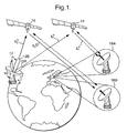
- an unknown transmitter 10 located in the United States of America 11 generates a signal which causes interference with satellite communications.
- the transmitter 10 has a radiation intensity pattern 12 with a sidelobe 12A directed to a first satellite 14 in a geostationary orbit, to which its signal propagates along a first uplink path l 1 u (dotted line). It also has a radiation pattern main lobe 12B directed to a second satellite 16 in such an orbit; its signal propagates along a second uplink path l 2 u to the satellite 16 and produces interference with communications signals using the latter.
- the unknown signal frequency is determined by spectrum analysis equipment which routinely monitors satellite channels.
- a typical communications satellite operating at Ku band (11 - 14 GHz) has 16 channels each 36 MHz wide and each capable of carrying 100 communications signals.
- the superscript "u" to path references l 1 u and l 2 u denotes uplink from the unknown transmitter 10.
- the satellites 14 and 16 are monitored by respective receivers in the form of ground station antennas 18A and 18B located in England and referred to collectively as receivers 18. They receive the signal from the unknown transmitter 10 and retransmit it along first and second downlink paths l 1 d and l 2 d to respective receivers 18. Here the superscript "d" denotes a downlink path to a monitoring receiver.
- the receivers 18 receive respective replicas of the unknown signal which include path delays and Doppler frequency shifts from satellite motion.
- the receivers 18 also transmit reference signals to the satellites 14 and 16 respectively, these signals being replicas of one another which are phase-locked together when transmitted initially.
- the satellites 14 and 16 return frequency shifted equivalents of the reference signals to respective receivers 18.
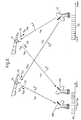
- signal correlation is affected by satellite velocity and acceleration components along the lines joining the satellite to the source and receiver. As will be described later in more detail, it has been found that during a geolocation measurement these components can be sufficiently different at different times to make correlation obtainable on some occasions but not others.
- Figure 2 is marked with arrows 20 to indicate parameters comprising components of satellite velocity and acceleration (eg v 1u , a 1u ) in the directions of the source 10 and receivers 18, together with signal time delay and associated signal paths as defined in the table below.
- the present invention involves processing which counteracts time varying DFO and preferably also time varying time dilation; the latter is depicted in Figure 2 by a linear source time axis 22 and a non-linear receiver time axis 24.
- the axes 22 and 24 indicate that there is a time varying time separation or dilation between successive signals arriving at a receiver 18 because of satellite motion.
- v 2d Satellite 16 velocity component along downlink path l 2 d to Receiver 18B a 1u Satellite 14 acceleration component along uplink path l 1 u to Source 10.
- Figure 2 shows what would happen to points originally regularly spaced on a waveform which passes over a path in space and is subjected to time varying Doppler effect.
- An analogue to digital converter (ADC) is used to sample a received signal and gives a regular set of samples to a signal which has undergone Doppler effect; these samples require timing adjustment, in one of the data sets z 1 or z 2 in Equation (2), in order to correspond to samples in the other data set which have undergone a different degree of Doppler effect.
- Figure 2 does not portray this - but instead what is shown is the result of differential Doppler effect on an array of points on a waveform which were originally regularly spaced. The dilation differs across four receiver channels to be described later, and is shown schematically at 22 for a single channel.
- a signal processing system for a transmitter location system (TLS) of the invention is shown schematically and indicated generally by 30. It is emphasised that this drawing is schematic and does not show all system features in detail. It will be described in outline only, because transmitter location is described in great detail in the prior art of US Pat No 5,008,679 and published PCT Appln No WO 97/11383. Readers of this specification are referred to PCT Appln No WO 97/11383 for a detailed description of how transmitter location may be put into practice, except as regards measurement of additional parameters and complex correlation function processing to achieve satellite motion compensation in accordance with this invention.
- the processing system 30 is illustrated functionally rather than in terms of actual items of apparatus; some items subsume multiple functions and others shown separately may be implemented together as a single device.
- the processing system 30 has four channels 32AR, 32AU, 32BR and 32BU; suffixes A and B indicate association with receivers 18A and 18B respectively and suffixes R and U indicate association with reference and unknown signals respectively. Components have like numerical references with differing suffixes distinguishing channels. The channels and their components will be referred to without suffixes to indicate any or all without differentiation, and with suffixes if necessary to be specific.
- Receiver 18A is connected to channels 32AU and 32AR
- receiver 18B is connected to channels 32BU and 32BR.
- Each channel 32 contains a series-connected arrangement of a mixer stage 34 for frequency down conversion and analogue filtering, an analogue to digital converter (ADC) 36 and an exponentiation stage 38 (H) for conversion of real signals to complex equivalents with in-phase and quadrature components.
- the mixers 34 are connected to a common local oscillator signal feed LO.
- Outputs from exponentiation stages 38AU and 38BU pass to a first correlation processing stage 40U, and that from the exponentiation stages 38AR and 38BR to a second correlation processing stage 40R.
- the processing stages 40U and 40R carry out parameter determination and correlation function processing as will be described later in more detail.
- Geometrical calculation and mapping to locate the unknown transmitter 10 is done in a mapping stage 42.
- the exponentiation, correlation processing and mapping stages 38, 40 and 42 may be implemented in a single computer.
- the processing system 30 operates as follows. Signals from the receivers 18 are amplified and fed to the mixer stages 34 where they are filtered and downconverted to a centre frequency suitable for analogue to digital (A/D) conversion. Downconversion takes place in several stages, with filtering to define the relevant signal frequency band in each case and to prevent aliasing at the A/D stage. Mixer stages 34AU and 34BU are tuned to extract the unknown signal, and mixer stages 34AR and 34BR are tuned to extract the reference signal.
- A/D analogue to digital
- the ADCs 36 sample signals from the respective mixer stages 34 using automatic level control (ALC) to minimise the effect of quantisation noise.
- the signal samples so formed are real, and the exponentiation stages 38 convert them to analytic or complex form using the Hilbert Transform.
- a set s 1 (t) of signal samples from channel 32AU is converted to an analytic sample set z 1 (t) which is then conjugated to form a set z 1 *(t).
- a similar procedure but without conjugation is followed for channel 32BU to produce a sample set z 2 (t).
- These two analytic sample sets for the unknown signal are then correlated together at 40U as will be described later to determine their DFO and DTO.
- Like sample sets are produced at 38AR and 38BR for the reference signal and are correlated at 40R.
- channel 32AU (x 1 (t i ), y 1 (t i )) or z 1 ; channel 32BU (x 2 (t i ), y 2 (t i )) or z 2 ; channel 32AR (r 1 (t i ), s 1 (t i )) or p 1 ; channel 32BR (r 2 (t i ), s 2 (t i )) or p 2 .
- Each correlation processing stage 40 correlates two sets of signal samples obtained respectively from distorted versions of the same original signal, the distortion arising from propagation via satellite relays; ie the two versions of the unknown signal in channels 32AU and 32BU are correlated with one another, as are the two versions of the reference signal in channels 32AR and 32BR.
- Each of the sample sets also has a noise component which is statistically independent of the noise component of sample sets from other channels.
- the procedure is to equalise the sample sets used in correlation, by introducing adjustable parameters into a correlation operation until the correlation function is a maximum; the parameters are related to the source/satellite/receiver geometry.
- the reference signal is used as in the prior art to remove noise which is correlated with that in the unknown signal, and the reference signal source provides a reference point with respect to which the unknown source location is determined.
- each correlation operation involved only fixed values of differential frequency offset (DFO or v) and differential time offset (DTO or ⁇ ).
- DFO differential frequency offset
- DTO differential time offset
- an expression for time varying DFO is used to compensate for satellite motion and if necessary time varying DTO is counteracted.
- the correlation operation is changed to implement this using a new correlation function different to that of Equation (1).
- the new function is referred to as the complex correlation function or CCF to distinguish it from the earlier expression; it is suitable for counteracting time varying DFO using geosynchronous satellites in orbits inclined to the ecliptic. It does not counteract time varying DTO, which is a different procedure to be described later.
- the constant b 1 is an initial value of DFO at the beginning of data recordal in a measurement; 2b 2 is the rate of change of DFO with time, referred to as the differential frequency rate offset or DFRO.
- Equation (3) expresses the discovery in accordance with the invention that in the case of geosynchronous satellites the variation of DFO over a measurement can often be assumed to be linear with time to a good approximation. If the variation of DFO with time is sufficiently non-linear, higher powers of time t - ie b 3 t 2 , b 4 t 3 etc - may be included in the expression for DFO in Equation (3), but these can be omitted under most circumstances. They would be included if the motion of the satellite intercept platform were to require it, but at the expense of additional processing.
- the parameters ⁇ 0 and b 2 are determined by inserting trial values of each into Equation (2), evaluating the CCF and iterating this procedure to find the maximum value of the correlation surface
- the correlation function A( ⁇ 0 ,b 1 ,b 2 ) is applicable to situations where the satellite relays or intercept platforms are geostationary (GEO) and large data sets are required, leading to long data collection times and changing DFO. It is also applicable in situations where other types of intercept platforms are used, eg aircraft, GEO - LEO (low Earth orbit) MEO - MEO (medium Earth orbit) and LEO - LEO satellite combinations, but the additional technique of time dilation compensation is then relevant as will be described later.
- GEO geostationary
- each step is a multiple of a basic increment determined by the time ⁇ t between successive signal samples (that is, a multiple of the inverse of the sampling rate) .
- the sampling rate is numerically equal to twice the sampling bandwidth set by low pass filters incorporated in the mixers 34.
- a fast Fourier transform (FFT) of the inner product of z 1 *(t) z 2 (t+ ⁇ 0 ) multiplied by exp(-2 ⁇ ib 2 t 2 ) is taken in order to convert it to the frequency domain.
- FFT fast Fourier transform
- a typical value of b 2 was found to be 0.05 Hz/second.
- the modulus of the complex correlation function (CCF) has a maximum in the frequency domain, and the values of ⁇ 0 and b 1 at this maximum provide the required DTO and DFO. This provides a computationally efficient method of evaluating the CCF for a range of values of( ⁇ 0 , b 1 , b 2 ).
- the foregoing procedure locates the CCF maximum approximately.
- the location accuracy can be improved by interpolation as described in detail in International Patent Application No WO 97/11383 referred to above in relation to the complex ambiguity function (CAF).
- CAF complex ambiguity function
- a range of values of the modulus (or modulus squared) of the CCF about its maximum value is taken, and interpolation is used to obtain a better estimate of the DTO, DFO and DFRO values.
- ⁇ 0 and ⁇ 0,ref are used to determine the uplink time difference of arrival TDOA u , ie the difference between the times of arrival of the two signals or signal replicas from the unknown source 10 at respective satellites 14 and 16.
- the values of b 1 , b 1,ref , b 2 and b 2,ref are used to determine the DFO values for the unknown signals and the reference signals. A theoretical treatment of this will now be given.
- the coefficients a 1.1u etc are not the same as the accelerations defined in the earlier table, but can be related to satellite velocities and accelerations.
- the full expression for the DTO becomes:
- the parameters ⁇ 0 , a 1 , and a 2 etc can be found by inspection, ie by equating coefficients of powers of time t in Equations (4) and (7).
- Equation (7) for the DTO ⁇ contains an uplink contribution which relates directly to the unknown source position to be determined, and a downlink contribution which is known from the satellite/receiver system geometry.
- the uplink contribution is referred to as the TDOA u .
- an equivalent expression for the DTO of the reference signal is subtracted from the DTO of the unknown source signal.
- the known geometry of the source/satellite/receiver system allows the DTO of the reference signal to be calculated, apart from biases (e.g. satellite processing delays) affecting it in the same way as they affect the source signal DTO. This is why the reference signal DTO is also measured.
- ⁇ 1u is the Doppler shift in frequency occurring on the uplink path l 1 u to satellite 14
- ⁇ 1u is the phase
- ⁇ u the wavelength of a signal (at its centre frequency) as received at the satellite 14 or 16 on uplink.
- Similar expressions for other system uplinks and downlinks are obtainable by change of indices.
- the unknown signal DFO is given by: where ⁇ u and ⁇ d are the free space wavelengths of the uplink and downlink signals respectively at their centre frequencies, and bias arises from satellite turnaround frequency shift and from satellite positional error.
- the reference signal DFO is similarly given by:
- the DDROA u is the difference in Doppler-rates measured along the paths from the unknown source 10 to the satellite intercept platform 14 and 16. It is useful for the location of moving sources.
- the DDROA can be expressed in terms of the DFRO by direct differentiation of (12) as follows:
- the uplink TDOA (TDOA u as in (8)) and the uplink FDOA (FDOA u as in (12)) are used in the process of emitter position location of stationary RF sources (on the Earth's surface), as in the prior art of published International Application No WO 97/11383.
- the DDROA u is not used explicitly.
- the effect of satellite acceleration, which gives rise to the DDROA u is counteracted in the CCF as previously described using trial values of the parameter b 2 as described earlier. This parameter must be utilised in evaluating the CCF even when it is not needed further in locating the source 10. This is because the RF emitter location problem has two parts.
- the first is detection of the peak of the CCF and the second is relating the peak of the CCF to a position on the Earth's surface.
- the first phase is sensitive to the effects of satellite motion; requiring b 2 as a compensation parameter in addition to those used in prior art ( ⁇ 0 and b 1 ).
- the source 10 is located by using the determined TDOA u and FDOA u values to the Earth's surface by prior art geometrical methods. Firstly, the parameters ⁇ 0 , b 1 and b 2 are obtained for the unknown and reference signals by maximising the CCF in Equation (2) as described earlier. The values of b 1 , b 1,ref , b 2 and b 2,ref are used to determine the signal and reference DFO values by insertion in Equation (3) with time t set to zero. This sets DFO as its instantaneous value at the beginning of data gathering - it is convenient to correct DFO to the value at this time but not essential.
- Equation (12) The values of ⁇ and ⁇ ref are substituted into Equation (12) to determine FDOA u .
- time t is set to zero; a consequence of this is that the location of the source 10 is determined using satellite ephemeris data (instantaneous positions in space) associated with the time at the start of sampling.
- TDOA u is multiplied by c the velocity of light to give differential slant range (DSR), this being the difference between the two signal path lengths to the signal relay satellites 14 and 16 from a transmitting station, ie either the reference transmitter location 18A/18B or the unknown source 10.
- FDOA u is multiplied by ⁇ u the signal wavelength in the uplink path to give the differential slant range rate (DSRR) or time rate of change of DSR.
- DSRR differential slant range rate
- Figure 4 is a pseudo-three-dimensional view of the prior art complex ambiguity function of Equation (1) plotted against DTO and DFO. All that can be seen is noise.
- Figure 5 is a similar plot of the complex correlation function of Equation (2) in accordance with the invention. In Figure 5 a sharp correlation maximum 50 is fully resolved and stands well above the noise at 52.
- the CCF must also be focused in the time dimension to compensate for time dilation. This is necessary to compensate for a time delay ⁇ 0 that varies appreciably in the course of data collection for a measurement.
- the CCF of Equation (2) only compensates for DFO variation in the sampling interval T. It does not compensate for time dilation, ie DTO variation in this interval. DTO variation is counteracted by periodic replication or excision of samples to compensate for samples in one data set (z 1 or p 1 ) being out of step with those in the associated data set (z 2 or p 2 ). For a measurement using two satellites, one geostationary and the other low earth orbit, it might involve inserting or removing one sample in every few hundred in a data set having in the order of a million samples. A phase correction is also required, and is applied to all samples in a data set following an insertion or excision, together with the inserted sample if this occurs. Successive phase corrections accumulate, each one being applied from the point of insertion or excision through the subsequent samples in the data set.
- the timing of the sample adjustments, insertions/excisions is determined from the time taken for a sample slip to occur.
- a slip occurs when the value of time dilation changes by an amount equal to the sampling interval at the ADC.
- the time to the mth slip (total time dilation of m sampling intervals) is estimated by one of two approaches: either (a) from the spread of the ambiguity surface, in the time direction, across the sampling interval, or (b) from use of the ⁇ 0 , b 1 , b 2 parameters obtained from maximising the CCF as described earlier.
- the correlation processor selects samples for removal from or replication in a set of data samples on the basis of the complex correlation function's time dimension spread over an interval in which the data set was obtained. If a CCF peak can be obtained from data without time dilation compensation, the number of time intervals ⁇ t over which the correlation is spread is estimated. For a spread of K time intervals, the number of samples between positions of adjustment (successive sample slips) of the data set is N/K where N is the number of samples in the data set.
- the data set z 1 or z 2 (see Equation (2)) selected for adjustment is a matter of implementation convenience and therefore arbitrary in principle; eg if z 1 corresponds to a signal expanded by time dilation, it can be contracted by sample removal to correct it, or alternatively z 2 may be expanded to match it.
- the selected data set is contracted or expanded by the removal or insertion of samples according to which of the two data sets is selected for adjustment and also according to whether the time dilation determined is positive or negative; if z 1 is selected, it is expanded if the time dilation is negative, which corresponds to rate of change of DTO being negative.
- t m is the time from initiation of sampling to the mth replicated or removed sample
- ⁇ m is the total time dilation experienced up to t m
- m is the number of sampling intervals removed or inserted to counteract time dilation
- ⁇ t is the sampling interval (time between successive ADC samples)
- ⁇ is the wavelength at the centre frequency of the signal sampling band before any frequency downconversion at a receiver 18.
- the parameter b ' / 1 is an estimate of the time invariant component of DFO b 1 with any systematic error (due to satellite turnaround frequency change) corrected using an estimate derived from the reference signal.
- b ' / 1 may be another parameter which is varied in steps in maximising the modulus of the CCF. It is also possible to exploit b 2 in the above expression as an independent parameter varied in steps, thereby dissociating time dilation and time variation of DFO.
- Equation (14) If the effects of satellite motion are not too severe, it is possible to omit the quadratic second term in Equation (14) in t m 2 , and apply the resulting linear correction.
- the exponent in the expression for P is positive or negative according to whether the preceding sample is omitted or inserted; f is the centre frequency of the samples' signal after downconversion for input to an analogue to digital converter, and ⁇ t is the interval between successive ADC samples.
- the samples' signal band is set by an anti-aliasing low-pass filter.
- the modulus of the CCF is maximised to obtain approximate values of DFO and the parameters ⁇ 0 , b 1 and b 2 as previously discussed.
- Time dilation compensation is then implemented by inserting or excising samples as appropriate and adjusting phase in each of the four data sets z 1 , z 2 , p 1 , p 2 to produce compensated equivalents.
- the CCF is then maximised again using the compensated data sets so formed to provide better values of DTO, DFO and if required DFRO and DDROA.
- T -1 and D -1 notation are used to indicate translation compensation and frequency distortion compensation respectively, the superscripts denoting reversal of effects introduced by system geometry and kinematics.
- the brackets [] indicate a vector comprising the signal samples. Translation of a relay satellite leads to time dilation because it alters the signal path and therefore also the associated time of flight.
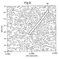
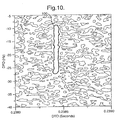
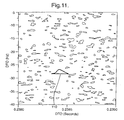
- FIGs 8 to 11 the effects of counteracting DFO variation and time dilation in accordance with the invention are illustrated graphically.
- DFO varies with DTO over a region 80 which includes error limits.
- Figure 9 illustrates the effect of frequency compensation alone, ie counteracting change in DFO.
- a region 90 is produced which is parallel to the DFO axis indicating DFO is now constant.
- Figure 10 is the equivalent of Figure 9 for time or DTO compensation alone, and shows a region 100 of constant DTO. The combination of both these procedures is shown in Figure 11, which shows a single peak of constant DFO and DTO. Compensation for DTO variation was carried out using the linear term in Equation (14) only.
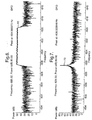
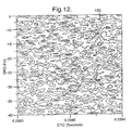
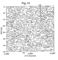
- Figures 12 to 14 illustrate graphically the effect of introducing noise. Except as regards noise they were produced using the same data as Figures 8 to 11, and they would show precisely the same features absent the noise. It can be seen that DTO and DFO are not visible in Figures 12 and 13, either without compensation (Figure 12) or with compensation for only one of frequency distortion and time distortion (Figure 13), which give like results.
- Figure 14 has a single peak 140 easily discemable above surrounding noise such as 142; it demonstrates that compensation for both frequency and time distortion in accordance with this invention leads to DTO and DFO values being obtainable despite the presence of noise.
Landscapes
- Engineering & Computer Science (AREA)
- Radar, Positioning & Navigation (AREA)
- Remote Sensing (AREA)
- Physics & Mathematics (AREA)
- General Physics & Mathematics (AREA)
- Computer Networks & Wireless Communication (AREA)
- Position Fixing By Use Of Radio Waves (AREA)
- Radio Relay Systems (AREA)
Applications Claiming Priority (3)
| Application Number | Priority Date | Filing Date | Title |
|---|---|---|---|
| GBGB9919525.7A GB9919525D0 (en) | 1999-08-19 | 1999-08-19 | Method and apparatus for locating the source of an unknown signal |
| GB9919525 | 1999-08-19 | ||
| PCT/GB2000/002940 WO2001014902A1 (en) | 1999-08-19 | 2000-07-31 | Method and apparatus for locating the source of an unknown signal |
Publications (2)
| Publication Number | Publication Date |
|---|---|
| EP1204882A1 EP1204882A1 (en) | 2002-05-15 |
| EP1204882B1 true EP1204882B1 (en) | 2005-09-28 |
Family
ID=10859363
Family Applications (1)
| Application Number | Title | Priority Date | Filing Date |
|---|---|---|---|
| EP00949742A Expired - Lifetime EP1204882B1 (en) | 1999-08-19 | 2000-07-31 | Method and apparatus for locating the source of an unknown signal |
Country Status (15)
| Country | Link |
|---|---|
| US (1) | US6618009B2 (enExample) |
| EP (1) | EP1204882B1 (enExample) |
| JP (1) | JP4782336B2 (enExample) |
| KR (1) | KR100810923B1 (enExample) |
| CN (1) | CN1249448C (enExample) |
| AR (1) | AR025074A1 (enExample) |
| AT (1) | ATE305615T1 (enExample) |
| AU (1) | AU768011B2 (enExample) |
| BR (1) | BR0013412A (enExample) |
| CA (1) | CA2380802C (enExample) |
| DE (1) | DE60022889T2 (enExample) |
| GB (2) | GB9919525D0 (enExample) |
| MX (1) | MXPA02001697A (enExample) |
| WO (1) | WO2001014902A1 (enExample) |
| ZA (1) | ZA200200799B (enExample) |
Cited By (1)
| Publication number | Priority date | Publication date | Assignee | Title |
|---|---|---|---|---|
| EP3675386A1 (en) * | 2018-12-31 | 2020-07-01 | Atos IT Solutions and Services GmbH | System and method for geolocating satellite terminals causing interference |
Families Citing this family (92)
| Publication number | Priority date | Publication date | Assignee | Title |
|---|---|---|---|---|
| GB2373940A (en) | 2001-03-27 | 2002-10-02 | Secr Defence | Locating the source of an unknown signal |
| FR2823857B1 (fr) | 2001-04-23 | 2006-11-24 | Agence Spatiale Europeenne | Procede de determination de la position d'une balise emettrice |
| WO2004052027A2 (en) * | 2002-11-27 | 2004-06-17 | Cognio, Inc | System and method for locating sources of unknown wireless radio signals |
| WO2006085916A2 (en) * | 2004-06-11 | 2006-08-17 | Bae Systems Information And Electronic Systems Integration Inc. | Single platform geolocation method and apparatus |
| US7783110B2 (en) * | 2004-12-01 | 2010-08-24 | Bae Systems Information And Electronic Systems Integration Inc. | Semicoherent channel estimator |
| JP4592506B2 (ja) * | 2005-06-15 | 2010-12-01 | 株式会社東芝 | アップリンク干渉源位置特定装置及びその方法 |
| CN101313621A (zh) * | 2005-09-27 | 2008-11-26 | 高通股份有限公司 | 使用具有定时偏移的传输器的位置定位 |
| US7508344B2 (en) * | 2005-11-29 | 2009-03-24 | L-3 Communications Integrated Systems, Lp | Systems and methods for TDOA/FDOA location |
| US7498986B2 (en) * | 2005-12-05 | 2009-03-03 | Honeywell International Inc. | Methods and systems for locating actuators for improvised explosive devices |
| GB0606501D0 (en) * | 2006-03-31 | 2006-05-10 | Qinetiq Ltd | Satellite ephemeris error |
| JP2008064566A (ja) * | 2006-09-06 | 2008-03-21 | Mitsubishi Electric Corp | 軌道推定方法とその装置 |
| GB2443226B (en) * | 2006-10-28 | 2011-08-17 | Qinetiq Ltd | Method and apparatus for locating the source of an unknown signal |
| US7471245B2 (en) * | 2007-01-31 | 2008-12-30 | L3 Communications Integrated Systems, L.P. | Method and apparatus for estimating geolocations |
| US7667640B2 (en) * | 2007-04-13 | 2010-02-23 | Glowlink Communications Technology, Inc. | Determining a geolocation solution of an emitter on earth using satellite signals |
| US7663547B2 (en) * | 2007-04-13 | 2010-02-16 | Glowlink Communications Technology, Inc. | Determining a geolocation solution of an emitter on earth based on weighted least-squares estimation |
| GB0719004D0 (en) * | 2007-09-27 | 2008-01-02 | Qinetiq Ltd | Interference power measurement |
| US7626546B2 (en) * | 2007-09-27 | 2009-12-01 | L-3 Communications Integrated Systems L.P. | Methods and systems for detection and location of multiple emitters |
| JP5359094B2 (ja) * | 2008-07-30 | 2013-12-04 | 日本電気株式会社 | 位置測定装置および位置測定方法 |
| JP2010060303A (ja) * | 2008-09-01 | 2010-03-18 | Mitsubishi Electric Corp | 測位装置 |
| US7911385B2 (en) * | 2009-02-27 | 2011-03-22 | Harris Corporation | RF transmitter geolocation system and related methods |
| US8488246B2 (en) | 2010-02-28 | 2013-07-16 | Osterhout Group, Inc. | See-through near-eye display glasses including a curved polarizing film in the image source, a partially reflective, partially transmitting optical element and an optically flat film |
| US8472120B2 (en) | 2010-02-28 | 2013-06-25 | Osterhout Group, Inc. | See-through near-eye display glasses with a small scale image source |
| US9134534B2 (en) | 2010-02-28 | 2015-09-15 | Microsoft Technology Licensing, Llc | See-through near-eye display glasses including a modular image source |
| JP2013521576A (ja) | 2010-02-28 | 2013-06-10 | オスターハウト グループ インコーポレイテッド | 対話式ヘッド取付け型アイピース上での地域広告コンテンツ |
| US20120249797A1 (en) | 2010-02-28 | 2012-10-04 | Osterhout Group, Inc. | Head-worn adaptive display |
| US9128281B2 (en) | 2010-09-14 | 2015-09-08 | Microsoft Technology Licensing, Llc | Eyepiece with uniformly illuminated reflective display |
| US9285589B2 (en) | 2010-02-28 | 2016-03-15 | Microsoft Technology Licensing, Llc | AR glasses with event and sensor triggered control of AR eyepiece applications |
| US8467133B2 (en) | 2010-02-28 | 2013-06-18 | Osterhout Group, Inc. | See-through display with an optical assembly including a wedge-shaped illumination system |
| US9091851B2 (en) | 2010-02-28 | 2015-07-28 | Microsoft Technology Licensing, Llc | Light control in head mounted displays |
| US8482859B2 (en) | 2010-02-28 | 2013-07-09 | Osterhout Group, Inc. | See-through near-eye display glasses wherein image light is transmitted to and reflected from an optically flat film |
| US9097890B2 (en) | 2010-02-28 | 2015-08-04 | Microsoft Technology Licensing, Llc | Grating in a light transmissive illumination system for see-through near-eye display glasses |
| US9182596B2 (en) | 2010-02-28 | 2015-11-10 | Microsoft Technology Licensing, Llc | See-through near-eye display glasses with the optical assembly including absorptive polarizers or anti-reflective coatings to reduce stray light |
| US9129295B2 (en) | 2010-02-28 | 2015-09-08 | Microsoft Technology Licensing, Llc | See-through near-eye display glasses with a fast response photochromic film system for quick transition from dark to clear |
| US9341843B2 (en) | 2010-02-28 | 2016-05-17 | Microsoft Technology Licensing, Llc | See-through near-eye display glasses with a small scale image source |
| US9366862B2 (en) | 2010-02-28 | 2016-06-14 | Microsoft Technology Licensing, Llc | System and method for delivering content to a group of see-through near eye display eyepieces |
| US10180572B2 (en) | 2010-02-28 | 2019-01-15 | Microsoft Technology Licensing, Llc | AR glasses with event and user action control of external applications |
| US20150309316A1 (en) | 2011-04-06 | 2015-10-29 | Microsoft Technology Licensing, Llc | Ar glasses with predictive control of external device based on event input |
| US9759917B2 (en) | 2010-02-28 | 2017-09-12 | Microsoft Technology Licensing, Llc | AR glasses with event and sensor triggered AR eyepiece interface to external devices |
| US9097891B2 (en) | 2010-02-28 | 2015-08-04 | Microsoft Technology Licensing, Llc | See-through near-eye display glasses including an auto-brightness control for the display brightness based on the brightness in the environment |
| US9229227B2 (en) | 2010-02-28 | 2016-01-05 | Microsoft Technology Licensing, Llc | See-through near-eye display glasses with a light transmissive wedge shaped illumination system |
| US9223134B2 (en) | 2010-02-28 | 2015-12-29 | Microsoft Technology Licensing, Llc | Optical imperfections in a light transmissive illumination system for see-through near-eye display glasses |
| US8477425B2 (en) | 2010-02-28 | 2013-07-02 | Osterhout Group, Inc. | See-through near-eye display glasses including a partially reflective, partially transmitting optical element |
| JP5599371B2 (ja) * | 2011-07-28 | 2014-10-01 | 三菱電機株式会社 | 測位装置 |
| WO2013066463A2 (en) * | 2011-08-12 | 2013-05-10 | Bae Systems Information & Electronic System Integration Inc. | Link 16-based geolocation of hostile jammers |
| US8866672B2 (en) | 2012-04-05 | 2014-10-21 | L-3 Communications Integrated Systems Lp | Cooperative systems and methods for TDOA-based emitter location |
| KR101224512B1 (ko) * | 2012-09-03 | 2013-01-21 | 한국항공우주연구원 | Tdoa 기법을 기반으로 하는 미지신호 발생원 위치 측정방법 |
| US9086471B2 (en) | 2012-12-05 | 2015-07-21 | Ses S.A. | Apparatuses, systems and methods for obtaining information about electromagnetic energy emitted from the earth, such as for locating an interference source on earth |
| US10720986B2 (en) | 2012-12-05 | 2020-07-21 | Ses S.A. | Apparatuses, systems and methods for obtaining information about electromagnetic energy emitted from the earth, such as for locating an interference source on earth |
| US11646918B2 (en) | 2013-03-15 | 2023-05-09 | Digital Global Systems, Inc. | Systems, methods, and devices for electronic spectrum management for identifying open space |
| US12256233B2 (en) | 2013-03-15 | 2025-03-18 | Digital Global Systems, Inc. | Systems and methods for automated financial settlements for dynamic spectrum sharing |
| US9702960B2 (en) * | 2013-03-15 | 2017-07-11 | Raytheon Company | Frequency difference of arrival (FDOA) for geolocation |
| US9288683B2 (en) | 2013-03-15 | 2016-03-15 | DGS Global Systems, Inc. | Systems, methods, and devices for electronic spectrum management |
| US10244504B2 (en) | 2013-03-15 | 2019-03-26 | DGS Global Systems, Inc. | Systems, methods, and devices for geolocation with deployable large scale arrays |
| US10231206B2 (en) | 2013-03-15 | 2019-03-12 | DGS Global Systems, Inc. | Systems, methods, and devices for electronic spectrum management for identifying signal-emitting devices |
| US10271233B2 (en) | 2013-03-15 | 2019-04-23 | DGS Global Systems, Inc. | Systems, methods, and devices for automatic signal detection with temporal feature extraction within a spectrum |
| US10122479B2 (en) | 2017-01-23 | 2018-11-06 | DGS Global Systems, Inc. | Systems, methods, and devices for automatic signal detection with temporal feature extraction within a spectrum |
| US10257729B2 (en) | 2013-03-15 | 2019-04-09 | DGS Global Systems, Inc. | Systems, methods, and devices having databases for electronic spectrum management |
| US10299149B2 (en) | 2013-03-15 | 2019-05-21 | DGS Global Systems, Inc. | Systems, methods, and devices for electronic spectrum management |
| US12356206B2 (en) | 2013-03-15 | 2025-07-08 | Digital Global Systems, Inc. | Systems and methods for automated financial settlements for dynamic spectrum sharing |
| US8750156B1 (en) | 2013-03-15 | 2014-06-10 | DGS Global Systems, Inc. | Systems, methods, and devices for electronic spectrum management for identifying open space |
| US10237770B2 (en) | 2013-03-15 | 2019-03-19 | DGS Global Systems, Inc. | Systems, methods, and devices having databases and automated reports for electronic spectrum management |
| US10257727B2 (en) | 2013-03-15 | 2019-04-09 | DGS Global Systems, Inc. | Systems methods, and devices having databases and automated reports for electronic spectrum management |
| US10219163B2 (en) | 2013-03-15 | 2019-02-26 | DGS Global Systems, Inc. | Systems, methods, and devices for electronic spectrum management |
| US10257728B2 (en) | 2013-03-15 | 2019-04-09 | DGS Global Systems, Inc. | Systems, methods, and devices for electronic spectrum management |
| CN104426821B (zh) * | 2013-08-30 | 2018-01-19 | 普天信息技术研究院有限公司 | 一种上行频率补偿的方法 |
| JP2017511885A (ja) * | 2014-02-26 | 2017-04-27 | コーエン, クラーク, エマーソンCOHEN, Clark, Emerson | 性能及びコストが改善されたグローバルナビゲーション衛星システムアーキテクチャ |
| US10444371B2 (en) * | 2014-03-21 | 2019-10-15 | The Boeing Company | Interference geolocation using a satellite constellation |
| CA2975448C (en) | 2015-02-09 | 2019-12-31 | Concentric Real Time, Llc | Radio receiver for determining location of a signal source |
| EP3156814B1 (en) | 2015-10-14 | 2024-03-27 | Bull Sas | Method for locating a terrestrial transmitting source of an unknown signal |
| KR101752723B1 (ko) * | 2015-10-29 | 2017-06-30 | 국방과학연구소 | 다중 caf map 비컨 위치추정 방법 |
| WO2017109951A1 (ja) * | 2015-12-25 | 2017-06-29 | 三菱電機株式会社 | 速度推定装置 |
| US11187778B2 (en) * | 2016-01-13 | 2021-11-30 | Hoopo Systems Ltd. | Method and system for radiolocation |
| US10498951B2 (en) | 2017-01-23 | 2019-12-03 | Digital Global Systems, Inc. | Systems, methods, and devices for unmanned vehicle detection |
| US12183213B1 (en) | 2017-01-23 | 2024-12-31 | Digital Global Systems, Inc. | Unmanned vehicle recognition and threat management |
| US12205477B2 (en) | 2017-01-23 | 2025-01-21 | Digital Global Systems, Inc. | Unmanned vehicle recognition and threat management |
| US10459020B2 (en) | 2017-01-23 | 2019-10-29 | DGS Global Systems, Inc. | Systems, methods, and devices for automatic signal detection based on power distribution by frequency over time within a spectrum |
| US10529241B2 (en) | 2017-01-23 | 2020-01-07 | Digital Global Systems, Inc. | Unmanned vehicle recognition and threat management |
| US10700794B2 (en) | 2017-01-23 | 2020-06-30 | Digital Global Systems, Inc. | Systems, methods, and devices for automatic signal detection based on power distribution by frequency over time within an electromagnetic spectrum |
| CN107807374A (zh) * | 2017-10-26 | 2018-03-16 | 慧众行知科技(北京)有限公司 | 一种时变参数估计方法及系统 |
| IL256679B2 (en) | 2017-12-31 | 2023-02-01 | Elta Systems Ltd | System and methods for locating a signal source |
| KR102162484B1 (ko) * | 2018-07-24 | 2020-10-06 | 인하대학교 산학협력단 | 미식별 cospas-sarsat 비콘 위치 추정 방법 및 시스템 |
| US10943461B2 (en) | 2018-08-24 | 2021-03-09 | Digital Global Systems, Inc. | Systems, methods, and devices for automatic signal detection based on power distribution by frequency over time |
| RU2714303C1 (ru) * | 2019-05-20 | 2020-02-14 | Федеральное государственное бюджетное образовательное учреждение высшего образования "Санкт-Петербургский государственный университет телекоммуникаций им. проф. М.А. Бонч-Бруевича" | Разностно-дальномерный способ определения местоположения источника радиоизлучения в условиях многолучевого распространения радиоволн |
| JP7178960B2 (ja) * | 2019-06-05 | 2022-11-28 | 三菱電機株式会社 | 位置推定装置、位置推定システム、位置推定方法、およびプログラム |
| US12069602B2 (en) * | 2019-08-22 | 2024-08-20 | Skylo Technologies, Inc. | Time delay estimations between wireless nodes |
| US11515937B2 (en) | 2019-08-22 | 2022-11-29 | Skylo Technologies, Inc. | Hub communication with a satellite network or a terrestrial network |
| FR3105836B1 (fr) * | 2019-12-31 | 2022-12-16 | Thales Sa | Procedes et dispositifs de geolocalisation d'un premier terminal de telecommunication satellite, programmes d'ordinateur associes |
| CN111929668B (zh) * | 2020-06-30 | 2023-09-19 | 华诺星空技术股份有限公司 | 基于量化区间统计的无线电侦测的测距方法及系统 |
| KR20230065266A (ko) * | 2020-09-11 | 2023-05-11 | 퀄컴 인코포레이티드 | 포지셔닝 측정을 위한 타이밍 그룹 표시 |
| CN117280840A (zh) * | 2021-05-10 | 2023-12-22 | Oppo广东移动通信有限公司 | 无线通信的方法、终端设备和网络设备 |
| US12352877B1 (en) * | 2021-07-08 | 2025-07-08 | Ast & Science, Llc | Dynamic triangulation of active user equipment location via satellite radio access technology (RAT) |
| JPWO2024189744A1 (enExample) * | 2023-03-13 | 2024-09-19 |
Family Cites Families (7)
| Publication number | Priority date | Publication date | Assignee | Title |
|---|---|---|---|---|
| JPS6465473A (en) * | 1987-09-04 | 1989-03-10 | Nec Corp | Satellite communication and position measurement system for moving body |
| JPS6465474A (en) * | 1987-09-04 | 1989-03-10 | Nec Corp | Satellite communicate and position measurement system for moving body |
| US5008679A (en) * | 1990-01-31 | 1991-04-16 | Interferometrics Incorporated | Method and system for locating an unknown transmitter |
| US5594452A (en) * | 1994-12-01 | 1997-01-14 | Interferometrics, Inc. | Method and system for locating an unknown transmitter using calibrated oscillator phases |
| KR100319993B1 (ko) * | 1995-09-20 | 2002-06-20 | 더 세크리터리 오브 스테이트 포 디펜스 | 미지신호의소스의위치탐색방법및장치 |
| US5936571A (en) * | 1997-01-31 | 1999-08-10 | Lockheed Martin Corporation | Integrated GPS/interference location system |
| KR19990048998A (ko) * | 1997-12-11 | 1999-07-05 | 전주범 | 고속광대역 신호탐지 시스템 |
-
1999
- 1999-08-19 GB GBGB9919525.7A patent/GB9919525D0/en not_active Ceased
- 1999-09-09 GB GBGB9921173.2A patent/GB9921173D0/en not_active Ceased
-
2000
- 2000-07-31 AT AT00949742T patent/ATE305615T1/de not_active IP Right Cessation
- 2000-07-31 JP JP2001519206A patent/JP4782336B2/ja not_active Expired - Lifetime
- 2000-07-31 CA CA002380802A patent/CA2380802C/en not_active Expired - Lifetime
- 2000-07-31 BR BR0013412-0A patent/BR0013412A/pt not_active IP Right Cessation
- 2000-07-31 CN CNB00811773XA patent/CN1249448C/zh not_active Expired - Fee Related
- 2000-07-31 AU AU63016/00A patent/AU768011B2/en not_active Expired
- 2000-07-31 WO PCT/GB2000/002940 patent/WO2001014902A1/en not_active Ceased
- 2000-07-31 MX MXPA02001697A patent/MXPA02001697A/es active IP Right Grant
- 2000-07-31 DE DE60022889T patent/DE60022889T2/de not_active Expired - Lifetime
- 2000-07-31 KR KR1020027002169A patent/KR100810923B1/ko not_active Expired - Lifetime
- 2000-07-31 EP EP00949742A patent/EP1204882B1/en not_active Expired - Lifetime
- 2000-08-08 AR ARP000104087A patent/AR025074A1/es active IP Right Grant
-
2001
- 2001-09-19 US US09/955,224 patent/US6618009B2/en not_active Expired - Lifetime
-
2002
- 2002-01-29 ZA ZA200200799A patent/ZA200200799B/en unknown
Cited By (1)
| Publication number | Priority date | Publication date | Assignee | Title |
|---|---|---|---|---|
| EP3675386A1 (en) * | 2018-12-31 | 2020-07-01 | Atos IT Solutions and Services GmbH | System and method for geolocating satellite terminals causing interference |
Also Published As
| Publication number | Publication date |
|---|---|
| KR20020029928A (ko) | 2002-04-20 |
| AU768011B2 (en) | 2003-11-27 |
| US6618009B2 (en) | 2003-09-09 |
| EP1204882A1 (en) | 2002-05-15 |
| GB9921173D0 (en) | 1999-11-10 |
| JP2003507747A (ja) | 2003-02-25 |
| GB9919525D0 (en) | 1999-10-20 |
| JP4782336B2 (ja) | 2011-09-28 |
| ZA200200799B (en) | 2003-06-25 |
| CN1370279A (zh) | 2002-09-18 |
| AR025074A1 (es) | 2002-11-06 |
| DE60022889D1 (de) | 2005-11-03 |
| AU6301600A (en) | 2001-03-19 |
| CA2380802A1 (en) | 2001-03-01 |
| CN1249448C (zh) | 2006-04-05 |
| ATE305615T1 (de) | 2005-10-15 |
| DE60022889T2 (de) | 2006-06-08 |
| BR0013412A (pt) | 2002-04-30 |
| MXPA02001697A (es) | 2003-10-15 |
| US20020070889A1 (en) | 2002-06-13 |
| KR100810923B1 (ko) | 2008-03-10 |
| CA2380802C (en) | 2008-12-16 |
| HK1047473A1 (en) | 2003-02-21 |
| WO2001014902A1 (en) | 2001-03-01 |
Similar Documents
| Publication | Publication Date | Title |
|---|---|---|
| EP1204882B1 (en) | Method and apparatus for locating the source of an unknown signal | |
| CN1325926C (zh) | 用于定位未知信号的来源的方法和设备 | |
| EP0852017B1 (en) | Locating the source of an unknown signal | |
| US5955986A (en) | Low-power satellite-based geopositioning system | |
| US5008679A (en) | Method and system for locating an unknown transmitter | |
| US5594452A (en) | Method and system for locating an unknown transmitter using calibrated oscillator phases | |
| US6169514B1 (en) | Low-power satellite-based geopositioning system | |
| Pisanu et al. | Upgrading the Italian BIRALES system to a pulse compression radar for space debris range measurements | |
| Kroger et al. | The Mars observer differential one-way range demonstration | |
| HK1047473B (en) | Method and apparatus for locating the source of an unknown signal | |
| Gurevich et al. | Synchronization of remote time scales via satellite communication channels | |
| Date | 203, Rev. C Sequential Ranging |
Legal Events
| Date | Code | Title | Description |
|---|---|---|---|
| PUAI | Public reference made under article 153(3) epc to a published international application that has entered the european phase |
Free format text: ORIGINAL CODE: 0009012 |
|
| 17P | Request for examination filed |
Effective date: 20020119 |
|
| AK | Designated contracting states |
Kind code of ref document: A1 Designated state(s): AT BE CH CY DE DK ES FI FR GB GR IE IT LI LU MC NL PT SE |
|
| 17Q | First examination report despatched |
Effective date: 20021128 |
|
| GRAP | Despatch of communication of intention to grant a patent |
Free format text: ORIGINAL CODE: EPIDOSNIGR1 |
|
| GRAS | Grant fee paid |
Free format text: ORIGINAL CODE: EPIDOSNIGR3 |
|
| GRAA | (expected) grant |
Free format text: ORIGINAL CODE: 0009210 |
|
| AK | Designated contracting states |
Kind code of ref document: B1 Designated state(s): AT BE CH CY DE DK ES FI FR GB GR IE IT LI LU MC NL PT SE |
|
| PG25 | Lapsed in a contracting state [announced via postgrant information from national office to epo] |
Ref country code: NL Free format text: LAPSE BECAUSE OF FAILURE TO SUBMIT A TRANSLATION OF THE DESCRIPTION OR TO PAY THE FEE WITHIN THE PRESCRIBED TIME-LIMIT Effective date: 20050928 Ref country code: AT Free format text: LAPSE BECAUSE OF FAILURE TO SUBMIT A TRANSLATION OF THE DESCRIPTION OR TO PAY THE FEE WITHIN THE PRESCRIBED TIME-LIMIT Effective date: 20050928 Ref country code: CH Free format text: LAPSE BECAUSE OF FAILURE TO SUBMIT A TRANSLATION OF THE DESCRIPTION OR TO PAY THE FEE WITHIN THE PRESCRIBED TIME-LIMIT Effective date: 20050928 Ref country code: FI Free format text: LAPSE BECAUSE OF FAILURE TO SUBMIT A TRANSLATION OF THE DESCRIPTION OR TO PAY THE FEE WITHIN THE PRESCRIBED TIME-LIMIT Effective date: 20050928 Ref country code: LI Free format text: LAPSE BECAUSE OF FAILURE TO SUBMIT A TRANSLATION OF THE DESCRIPTION OR TO PAY THE FEE WITHIN THE PRESCRIBED TIME-LIMIT Effective date: 20050928 Ref country code: BE Free format text: LAPSE BECAUSE OF FAILURE TO SUBMIT A TRANSLATION OF THE DESCRIPTION OR TO PAY THE FEE WITHIN THE PRESCRIBED TIME-LIMIT Effective date: 20050928 |
|
| REG | Reference to a national code |
Ref country code: GB Ref legal event code: FG4D |
|
| REG | Reference to a national code |
Ref country code: CH Ref legal event code: EP |
|
| REG | Reference to a national code |
Ref country code: IE Ref legal event code: FG4D |
|
| REF | Corresponds to: |
Ref document number: 60022889 Country of ref document: DE Date of ref document: 20051103 Kind code of ref document: P |
|
| PG25 | Lapsed in a contracting state [announced via postgrant information from national office to epo] |
Ref country code: GR Free format text: LAPSE BECAUSE OF FAILURE TO SUBMIT A TRANSLATION OF THE DESCRIPTION OR TO PAY THE FEE WITHIN THE PRESCRIBED TIME-LIMIT Effective date: 20051228 Ref country code: SE Free format text: LAPSE BECAUSE OF FAILURE TO SUBMIT A TRANSLATION OF THE DESCRIPTION OR TO PAY THE FEE WITHIN THE PRESCRIBED TIME-LIMIT Effective date: 20051228 Ref country code: DK Free format text: LAPSE BECAUSE OF FAILURE TO SUBMIT A TRANSLATION OF THE DESCRIPTION OR TO PAY THE FEE WITHIN THE PRESCRIBED TIME-LIMIT Effective date: 20051228 |
|
| PG25 | Lapsed in a contracting state [announced via postgrant information from national office to epo] |
Ref country code: ES Free format text: LAPSE BECAUSE OF FAILURE TO SUBMIT A TRANSLATION OF THE DESCRIPTION OR TO PAY THE FEE WITHIN THE PRESCRIBED TIME-LIMIT Effective date: 20060108 |
|
| PG25 | Lapsed in a contracting state [announced via postgrant information from national office to epo] |
Ref country code: PT Free format text: LAPSE BECAUSE OF FAILURE TO SUBMIT A TRANSLATION OF THE DESCRIPTION OR TO PAY THE FEE WITHIN THE PRESCRIBED TIME-LIMIT Effective date: 20060228 |
|
| NLV1 | Nl: lapsed or annulled due to failure to fulfill the requirements of art. 29p and 29m of the patents act | ||
| REG | Reference to a national code |
Ref country code: CH Ref legal event code: PL |
|
| ET | Fr: translation filed | ||
| PG25 | Lapsed in a contracting state [announced via postgrant information from national office to epo] |
Ref country code: MC Free format text: LAPSE BECAUSE OF NON-PAYMENT OF DUE FEES Effective date: 20060731 Ref country code: IE Free format text: LAPSE BECAUSE OF NON-PAYMENT OF DUE FEES Effective date: 20060731 |
|
| PLBE | No opposition filed within time limit |
Free format text: ORIGINAL CODE: 0009261 |
|
| STAA | Information on the status of an ep patent application or granted ep patent |
Free format text: STATUS: NO OPPOSITION FILED WITHIN TIME LIMIT |
|
| 26N | No opposition filed |
Effective date: 20060629 |
|
| REG | Reference to a national code |
Ref country code: IE Ref legal event code: MM4A |
|
| PG25 | Lapsed in a contracting state [announced via postgrant information from national office to epo] |
Ref country code: CY Free format text: LAPSE BECAUSE OF FAILURE TO SUBMIT A TRANSLATION OF THE DESCRIPTION OR TO PAY THE FEE WITHIN THE PRESCRIBED TIME-LIMIT Effective date: 20050928 |
|
| REG | Reference to a national code |
Ref country code: GB Ref legal event code: 732E Free format text: REGISTERED BETWEEN 20101014 AND 20101020 |
|
| REG | Reference to a national code |
Ref country code: GB Ref legal event code: 732E Free format text: REGISTERED BETWEEN 20101021 AND 20101027 |
|
| REG | Reference to a national code |
Ref country code: DE Ref legal event code: R082 Ref document number: 60022889 Country of ref document: DE Representative=s name: BEETZ & PARTNER PATENT- UND RECHTSANWAELTE, DE |
|
| REG | Reference to a national code |
Ref country code: DE Ref legal event code: R082 Ref document number: 60022889 Country of ref document: DE Representative=s name: BEETZ & PARTNER PATENT- UND RECHTSANWAELTE, DE Effective date: 20120709 Ref country code: DE Ref legal event code: R081 Ref document number: 60022889 Country of ref document: DE Owner name: KRATOS INTEGRAL HOLDINGS, LLC (EINE GESELLSCHA, US Free format text: FORMER OWNER: INTEGRAL SYSTEMS, INC.,, LANHAM, MD., US Effective date: 20120709 Ref country code: DE Ref legal event code: R082 Ref document number: 60022889 Country of ref document: DE Representative=s name: BEETZ & PARTNER MBB, DE Effective date: 20120709 Ref country code: DE Ref legal event code: R082 Ref document number: 60022889 Country of ref document: DE Representative=s name: BEETZ & PARTNER MBB PATENTANWAELTE, DE Effective date: 20120709 Ref country code: DE Ref legal event code: R082 Ref document number: 60022889 Country of ref document: DE Representative=s name: BEETZ & PARTNER MBB PATENT- UND RECHTSANWAELTE, DE Effective date: 20120709 |
|
| REG | Reference to a national code |
Ref country code: FR Ref legal event code: PLFP Year of fee payment: 16 |
|
| REG | Reference to a national code |
Ref country code: FR Ref legal event code: PLFP Year of fee payment: 17 |
|
| REG | Reference to a national code |
Ref country code: FR Ref legal event code: PLFP Year of fee payment: 18 |
|
| REG | Reference to a national code |
Ref country code: FR Ref legal event code: PLFP Year of fee payment: 19 |
|
| PGFP | Annual fee paid to national office [announced via postgrant information from national office to epo] |
Ref country code: LU Payment date: 20190729 Year of fee payment: 20 |
|
| PGFP | Annual fee paid to national office [announced via postgrant information from national office to epo] |
Ref country code: IT Payment date: 20190726 Year of fee payment: 20 Ref country code: DE Payment date: 20190729 Year of fee payment: 20 Ref country code: FR Payment date: 20190725 Year of fee payment: 20 |
|
| PGFP | Annual fee paid to national office [announced via postgrant information from national office to epo] |
Ref country code: GB Payment date: 20190729 Year of fee payment: 20 |
|
| REG | Reference to a national code |
Ref country code: DE Ref legal event code: R071 Ref document number: 60022889 Country of ref document: DE |
|
| REG | Reference to a national code |
Ref country code: GB Ref legal event code: PE20 Expiry date: 20200730 |
|
| PG25 | Lapsed in a contracting state [announced via postgrant information from national office to epo] |
Ref country code: GB Free format text: LAPSE BECAUSE OF EXPIRATION OF PROTECTION Effective date: 20200730 |