EP1204502B1 - Patin support - Google Patents
Patin support Download PDFInfo
- Publication number
- EP1204502B1 EP1204502B1 EP00941089A EP00941089A EP1204502B1 EP 1204502 B1 EP1204502 B1 EP 1204502B1 EP 00941089 A EP00941089 A EP 00941089A EP 00941089 A EP00941089 A EP 00941089A EP 1204502 B1 EP1204502 B1 EP 1204502B1
- Authority
- EP
- European Patent Office
- Prior art keywords
- guide bar
- support pad
- contact surface
- cutter head
- longitudinal direction
- Prior art date
- Legal status (The legal status is an assumption and is not a legal conclusion. Google has not performed a legal analysis and makes no representation as to the accuracy of the status listed.)
- Expired - Lifetime
Links
Images


Classifications
-
- B—PERFORMING OPERATIONS; TRANSPORTING
- B23—MACHINE TOOLS; METAL-WORKING NOT OTHERWISE PROVIDED FOR
- B23B—TURNING; BORING
- B23B51/00—Tools for drilling machines
- B23B51/04—Drills for trepanning
-
- B—PERFORMING OPERATIONS; TRANSPORTING
- B23—MACHINE TOOLS; METAL-WORKING NOT OTHERWISE PROVIDED FOR
- B23B—TURNING; BORING
- B23B51/00—Tools for drilling machines
-
- B—PERFORMING OPERATIONS; TRANSPORTING
- B23—MACHINE TOOLS; METAL-WORKING NOT OTHERWISE PROVIDED FOR
- B23B—TURNING; BORING
- B23B2251/00—Details of tools for drilling machines
- B23B2251/56—Guiding pads
-
- Y—GENERAL TAGGING OF NEW TECHNOLOGICAL DEVELOPMENTS; GENERAL TAGGING OF CROSS-SECTIONAL TECHNOLOGIES SPANNING OVER SEVERAL SECTIONS OF THE IPC; TECHNICAL SUBJECTS COVERED BY FORMER USPC CROSS-REFERENCE ART COLLECTIONS [XRACs] AND DIGESTS
- Y10—TECHNICAL SUBJECTS COVERED BY FORMER USPC
- Y10S—TECHNICAL SUBJECTS COVERED BY FORMER USPC CROSS-REFERENCE ART COLLECTIONS [XRACs] AND DIGESTS
- Y10S408/00—Cutting by use of rotating axially moving tool
- Y10S408/705—Drilling deep holes
-
- Y—GENERAL TAGGING OF NEW TECHNOLOGICAL DEVELOPMENTS; GENERAL TAGGING OF CROSS-SECTIONAL TECHNOLOGIES SPANNING OVER SEVERAL SECTIONS OF THE IPC; TECHNICAL SUBJECTS COVERED BY FORMER USPC CROSS-REFERENCE ART COLLECTIONS [XRACs] AND DIGESTS
- Y10—TECHNICAL SUBJECTS COVERED BY FORMER USPC
- Y10T—TECHNICAL SUBJECTS COVERED BY FORMER US CLASSIFICATION
- Y10T408/00—Cutting by use of rotating axially moving tool
- Y10T408/55—Cutting by use of rotating axially moving tool with work-engaging structure other than Tool or tool-support
- Y10T408/557—Frictionally engaging sides of opening in work
- Y10T408/558—Opening coaxial with Tool
- Y10T408/5583—Engaging sides of opening being enlarged by Tool
- Y10T408/5586—Engaging surface subsequent to tool-action on that surface
-
- Y—GENERAL TAGGING OF NEW TECHNOLOGICAL DEVELOPMENTS; GENERAL TAGGING OF CROSS-SECTIONAL TECHNOLOGIES SPANNING OVER SEVERAL SECTIONS OF THE IPC; TECHNICAL SUBJECTS COVERED BY FORMER USPC CROSS-REFERENCE ART COLLECTIONS [XRACs] AND DIGESTS
- Y10—TECHNICAL SUBJECTS COVERED BY FORMER USPC
- Y10T—TECHNICAL SUBJECTS COVERED BY FORMER US CLASSIFICATION
- Y10T408/00—Cutting by use of rotating axially moving tool
- Y10T408/89—Tool or Tool with support
- Y10T408/892—Tool or Tool with support with work-engaging structure detachable from cutting edge
Definitions
- the present invention relates to a support pad/guide bar, which is intended to be mounted in a seat on the cutter head of a deep hole drill, said support pad/guide bar having a longitudinal direction and a cross-direction, and that the support pad/guide bar has. at least one contact surface, on the side thereof turned outwards in the mounted state, which is intended to co-operate with the hole wall.
- a support pad/guide bar is, according to the preamble of claim 1, e.g. known from US-A-4 596 498.
- the two most common systems in deep hole drilling are presently the STS (Single Tube System) system and the Ejector system, at which the support pad/guide bar according to the present invention may be used in connection with a deep hole drill which relates to both these systems.
- the support pads and guide bars which are arranged on the cutter head, are subjected to the formation of crack during the deep hole drilling.
- the support pads/guide bars are normally made of solid cemented carbide, whereby said support pads/guide bars may be exchangeably fixed on the cutter head or in various ways connected by soldering to the cutter head.
- the support pads/guide bars are exposed to high temperatures by the fact that the friction against the hole wall may be high.
- the present invention has as its aim the definition of a support pad/guide bar of the kind defined in the introduction, which is so designed that a substantially improved cooling of the support pad/guide bar is achieved.
- Another aim of the present invention is to increase the service life of the support pad/guide bar by reducing the occurrence of cracks in the support pad/guide bar.
- the cutter head of a deep hole drill illustrated in fig 1 is equipped with a support pad 1 as well as a guide bar 3.
- the support pad 1 and the guide bar 3 are received in seats and anchored in said seats by means of the principle for indexable inserts, i.e. by means of a screw (not visible in fig 1) which extends through a hole in the support pad 1/guide bar 3 and anchors this in the appurtenant seat thanks to the screw extending into a threaded hole in the cutter head.
- the cutter head is, in the usual way, equipped with a cutting insert and provided with openings and an inner channel for removal of chips, which are generated at drilling.
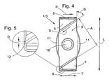
- the support pad 1/guide bar 3 shown in figs 2-4 is of a generally parallelepipedical basic shape and a generally rectangular shape in planar view, see fig 4.
- the support pad 1/guide bar 3 has a longitudinal direction L along a long side of the support pad 1/guide bar 3 and a cross-direction T along a short side of the support pad 1/guide bar 3.
- the support pad 1/guide bar 3 is, on the side turned outwards in the mounted position in the cutter head, provided with two, in planar view, triangular contact surfaces 5 and 7, which between themselves define a countersink 9, which in the shown embodiment, by virtue of the triangular shape of the contact surfaces 5, 7, extends diagonally across the support pad 1/guide bar 3.
- the limiting edges 2, 4 of the contact surfaces 5, 7 turned towards the centre of the support pad 1/guide bar 3 are in the main straight.
- the contact surfaces 5, 7, which in the mounted state of the support pad 1/guide bar 3 are turned outwards, are convex, as may be most clearly seen in fig 2.
- said convex contact surfaces 5, 7 have a certain radius of curvature, and in this connection it should be pointed out that normally support pads 1/guide bars 3 are not made for each drill diameter. but support pads 1/guide bars with same dimensions are used on all drills within a certain drill diameter range, the radius of curvature of the support pad 1/guide bar 3 corresponding to the radius of curvature of the cutter head of the drill with the smallest drill diameter in the range in question.
- the interior contact surface of the support pad 1/guide bar 3 i.e. the surface which is not shown in figs 2-4 and which is received in an appurtenant seat in the cutter head, is plane.
- the countersink 9 is defined by a plane surface, which is indicated by the fact that the dimension C given in fig 3 is constant all over the countersink 9. Said dimension C should preferably be approx. 20 % of the radius of curvature of the convex contact surfaces 5, 7.
- the support pad 1/guide bar 3 is also provided with a through hole 10 for the receipt of a screw (not shown), by means of which the support pad 1/guide bar 3 is anchored in the appurtenant seat of the cutter head.
- the support pad 1/guide bar 3 is provided with chamfers 6, 8 at the short ends thereof.
- the chamfers 6, 8 are so formed that their fitting against the cutter head in fig 1 takes place without there being any level difference between the chamfers 6, 8 and the portions of the cutter head 1 which said chamfers 6, 8 fit against.
- the support pad 1/guide bar 3 is, on the long sides thereof, provided with projections 11, which in planar view have the shape of segments of a circle. Said projections 11 are intended to co-operate with recesses in the seats, said recesses, in planar view, having a shape corresponding to the projections 11.
- the projections 11 fix the support pad 1/guide bar 3 in the longitudinal direction L thereof when the support pad 1/guide bar 3 is situated in the appurtenant seat thereof.
- projections 11 in no way are necessary or constitute a presumption for the features, which define the present invention.
- the support pad/guide bar is not provided with projections 11.
- fig 5 a part of the support pad 1/guide bar 3, which is encircled in fig 4, is shown on a larger scale.
- the given dimension D should be in the interval 0,1-1,0 mm. If the dimension D in question for said surface 12 exceeds 1 mm, there is a risk that particles may press in between the contact surface 5, 7 and the hole wall.
- the surface 12 should preferably be softly rounded.
- the dimension A, see fig 4, of the countersink 9 is dependent of the dimension D of the surface 12. If the given dimension D of the surface 12, the dimensions of which are listed, increases, the dimension A decreases correspondingly while if the given dimension D of the surface 12 decreases, the dimension A increases correspondingly. It has been established that the angle B in fig 4 should have the value 55° ⁇ 10°.
- the function of the support pad 1/guide bar 3 described in figs 2-5 is the following.
- said support pad 1/guide bar 3 moves in the direction of the arrow P in fig 4.
- the upper contact surface 5 in fig 4 will be the surface that abuts against the hole wall.
- the lower contact surface 7 in fig 4 has, in principle, no active function.
- active contact surface 5 in fig 4 As for the upper, active contact surface 5 in fig 4, it is the left part thereof in fig 4 which constitutes the active part of the upper contact surface 5, i.e. said active part abuts against the hole wall.
- cooling medium commonly oil
- a part of said cooling medium flows on the outside of the cutter head and reaches the free end of said cutter head, i.e. where the chip removing machining is carried out.
- the cutter head of the deep hole drill illustrated in fig 1 is provided with axial channels for the cooling medium.
- this is not necessary in connection with the support pad 1/guide bar 3 according to the present invention, but said support pad 1/guide bar 3 may also be mounted on a cutter head which lacks special external channels for the cooling medium.
- cooling medium will flow in the countersink 9 in the direction of the arrow S.
- the countersink 9 having a diagonal extension, alternatively that the upper contact surface 5 is triangular, the cooling medium will pass near the left part of said upper contact surface 5, i.e. the active part of the contact surface 5. This ensures that there will be good cooling of said active part of the upper contact surface 5, which to a significant degree reduces the occurrence of cracks.
- the support pad 1/guide bar 3 is indexed 180°, i.e. the lower contact surface 7 in fig 4 assumes the location of the upper contact surface 5 in fig 4. Said indexing is prior art, i.e. nothing specifically for the present invention.
- the above described chamfers 6, 8 have the function when the aim is to bore a hole which is through a workpiece, the cutter head according to fig 1 will proceed past the bored-through end of the workpiece. Then, when the cutter head according to fig 1 is to be retracted through the workpiece after final drilling, it happens, when support pads/guide bars with a design according to prior art are used, that an edge of said support pads/guide bars becomes fastened in the workpiece. In order to avoid that this happens, the support pad/guide bar is provided with said chamfer 6, 8, which means that the cutter head may be retracted through the workpiece without there being any risk that the support pad/guide bar should fasten in the workpiece.
- the support pad 1'/guide bar 3' illustrated in figs 6 and 7 has the same basic shape in planar view as the support pad 1/guide bar 3 according to figs 2-5 and it is intended to be mounted in a cutter head according to fig 1 in the corresponding way as the support pad 1/guide bar 3 according to figs 2-5.
- the support pad 1'/guide bar 3' has a longitudinal direction L along a long side of the support pad 1'/guide bar 3' and a cross-direction T along a short side of the support pad 1'/guide bar 3'.
- the contact surfaces 5', 7' of the support pad 1'/guide bar 3' according to fig 6 consist of convex surfaces, which are situated on both sides of the hole 10 in the longitudinal direction of the support pad 1'/guide bar 3'.
- the bending radius of said convex contact surfaces 5', 7' in relation to the bending radius of the cutter head reference is made to what has been said in association with the embodiment according to figs 2-5.
- the limiting edge 2', 4', turned towards the hole 10, for the contact surfaces 5', 7' has a curved shape, said limiting edge 2', 4' bellying towards the hole 10, i.e. it is convex in respect of said contact surfaces 5', 7'.
- the convex bending of the limiting edge 2', 4' ensures that the contact surfaces 5', 7' relatively seen are larger than the contact surfaces 5, 7 of the support pad 1/guide bar 3 according to figs 2-5.
- an angle B' of the support pad 1'/guide bar 3' which corresponds to the angle B of the support pad 1/guide bar 3
- a line has been drawn through the end points of the limiting edge 2', see fig 6. What has been said above concerning the size of the angle B is also valid for the angle B'.
- the same is correspondingly valid as for the support pad 1/guide bar 3 according to figs 2-5 that only the contact surface 5', 7' situated closest to the chip removing end of the cutter head is the active contact surface, and that only an active part of said active contact surface abuts against the hole wall.
- the support pad 1'/guide bar 3' is, in the corresponding way as the support pad 1/guide bar 3 according to figs 2-5, indexable, i.e. when one of the contact surfaces, for instance 5', is worn out, the support pad 1'/guide bar 3' is indexed so that the contact surface 7' assumes the location of the upper contact surface 5'.
- the support pad 1'/guide bar 3' is, on the underside thereof, provided with a central countersink 13', whereby a frame 14' is formed around said countersink 13', which frame abuts against the bottom of the seats which the support pad 1'/guide bar 3' is received in when it is mounted on a cutter head of a deep hole drill, see fig 1. Thanks to the design of a frame 14', it is guaranteed that abutment against the bottom of the seat takes place in the area of the contact surfaces 5', 7' situated on the opposite side of the support pad 1'/guide bar 3', and not in a central area of the support pad 1'/guide bar 3'. What has been said above concerning the abutment of the support pad 1'/guide bar 3' against the bottom of the seat is also valid for the support pad 1/guide bar 3 according to figs 2-5 as well as other feasible embodiments of the present invention.
- the support pad 1; 1'/guide bar 3; 3' this is provided with a through hole 10 for receipt of a screw or the like for anchorage of the support pad 1; 1'/guide bar 3; 3' in the appurtenant seat thereof.
- the support pad/guide bar is of the type that is connected by soldering to the cutter head, i.e. it is not necessary that the support pad/guide bar has a through hole for the anchorage thereof in the seat.
Landscapes
- Engineering & Computer Science (AREA)
- Mechanical Engineering (AREA)
- Drilling Tools (AREA)
- Drilling And Boring (AREA)
- Adjustment Of The Magnetic Head Position Track Following On Tapes (AREA)
- Apparatus For Radiation Diagnosis (AREA)
- Mechanical Treatment Of Semiconductor (AREA)
Claims (7)
- Patin support (1 ; 1') / barre de guidage (3 ; 3'), prévu pour être monté dans un siège sur la tête de coupe d'un foret pour trou profond, le patin support (1 ; 1') / barre de guidage (3 ; 3') ayant une direction longitudinale (L) et une direction transversale (T), et ayant sur le côté, tournée vers l'extérieur à l'état monté, au moins une surface de contact (5, 7 ; 5', 7') qui est prévue pour coopérer avec la paroi du trou, et au moins une fraisure (9 ; 9') s'étendant de façon transverse par rapport à la direction longitudinale (L) du patin support (1 ; 1') / barre de guidage (3 ; 3'), caractérisé par le fait que la fraisure (9) a une extension formant un certain angle (B) avec la direction longitudinale (L) du patin support (1 ; 1') / barre de guidage (3 ; 3'), et que cet angle (B) est de 55 degrés ± 10 degrés.
- Patin support (1 ; 1') / barre de guidage (3 ; 3') selon la revendication 1, caractérisé par le fait que le patin support (1 ; 1') / barre de guidage (3 ; 3') a une surface de contact (5, 7 ; 5', 7') dans la zone de chacune des parties d'extrémité, qui est située à distance selon la direction longitudinale (L), que ces surfaces de contact (5, 7 : 5', 7') sont convexes, et que la fraisure (9 ; 9') est située entre ces surfaces de contact (5, 7 ; 5', 7').
- Patin support (1 ; 1') / barre de guidage (3 ; 3') selon l'une des revendications 1 et 2, caractérisé par le fait que la fraisure (9, 9') est définie par une surface plane.
- Patin support (1 ; 1') / barre de guidage (3 ; 3') selon l'une quelconque des revendications 1 à 3, caractérisé par le fait que des chanfreins (6, 8) sont ménagés dans la zone des petits côtés du patin support (1 ; 1') / barre de guidage (3 ; 3').
- Patin support (1 ; 1') / barre de guidage (3 ; 3') selon l'une quelconque des revendications 1 à 4, caractérisé par le fait que des chanfreins sont aussi ménagés dans la zone de connexion des grands côtés aux petits côtés du patin support (1 ; 1') / barre de guidage (3 ; 3').
- Patin support (1 ; 1') / barre de guidage (3 ; 3') selon l'une quelconque des revendications 1 à 5, caractérisé par le fait que la ligne limite (2, 4) de la surface de contact (5, 7) tournée vers le centre du patin support (1) / barre de guidage (3) est globalement droite.
- Patin support (1 ; 1') / barre de guidage (3 ; 3') selon l'une quelconque des revendications 1 à 5, caractérisé par le fait que la ligne limite (2', 4') de la surface de contact (5', 7') tournée vers le centre du patin support (1') / barre de guidage (3') présente une courbure convexe par rapport à la surface de contact (5', 7').
Applications Claiming Priority (3)
| Application Number | Priority Date | Filing Date | Title |
|---|---|---|---|
| SE9902355A SE517446C2 (sv) | 1999-06-21 | 1999-06-21 | Stödlist/Ledare |
| SE9902355 | 1999-06-21 | ||
| PCT/SE2000/001233 WO2000078487A1 (fr) | 1999-06-21 | 2000-06-14 | Patin support |
Publications (2)
| Publication Number | Publication Date |
|---|---|
| EP1204502A1 EP1204502A1 (fr) | 2002-05-15 |
| EP1204502B1 true EP1204502B1 (fr) | 2004-10-13 |
Family
ID=20416181
Family Applications (1)
| Application Number | Title | Priority Date | Filing Date |
|---|---|---|---|
| EP00941089A Expired - Lifetime EP1204502B1 (fr) | 1999-06-21 | 2000-06-14 | Patin support |
Country Status (9)
| Country | Link |
|---|---|
| US (1) | US6602028B1 (fr) |
| EP (1) | EP1204502B1 (fr) |
| JP (1) | JP4689908B2 (fr) |
| KR (1) | KR100676955B1 (fr) |
| CN (1) | CN1140368C (fr) |
| AT (1) | ATE279284T1 (fr) |
| DE (1) | DE60014923T2 (fr) |
| SE (1) | SE517446C2 (fr) |
| WO (1) | WO2000078487A1 (fr) |
Cited By (1)
| Publication number | Priority date | Publication date | Assignee | Title |
|---|---|---|---|---|
| USD1009108S1 (en) | 2020-09-21 | 2023-12-26 | Kyocera Unimerco Tooling A/S | Drill |
Families Citing this family (19)
| Publication number | Priority date | Publication date | Assignee | Title |
|---|---|---|---|---|
| DE10209924A1 (de) * | 2002-03-07 | 2003-09-25 | Beck August Gmbh Co | Führungsleiste für leistengeführte spanabhebende Werkzeuge |
| DE20219754U1 (de) * | 2002-12-19 | 2004-04-22 | Gühring, Jörg, Dr. | Tieflochbohrer mit auswechselbarem Schneideinsatz und auswechselbarer Führungsleiste |
| SE526676C2 (sv) * | 2003-05-20 | 2005-10-25 | Sandvik Intellectual Property | Eggbärande borrkropp för långhålsborrning med eggar förfärdigade i ett stycke med borrkroppen |
| SE526567C2 (sv) * | 2003-07-16 | 2005-10-11 | Sandvik Intellectual Property | Stödlist för långhålsborr med slityta i avvikande färg |
| FR2874341B1 (fr) * | 2004-08-17 | 2008-02-22 | Messier Dowty Sa | Tete de forage profond et procede de forage profond pour le forage d'une piece de fabrication |
| JP4961245B2 (ja) * | 2007-04-02 | 2012-06-27 | ユニタック株式会社 | 深穴切削装置 |
| SE533277C2 (sv) * | 2008-12-19 | 2010-08-10 | Sandvik Intellectual Property | Borrkropp samt stödlist härför |
| DE202010003288U1 (de) | 2010-03-05 | 2010-08-05 | Botek Präzisionsbohrtechnik Gmbh | Führungsleiste |
| WO2012117817A1 (fr) * | 2011-02-28 | 2012-09-07 | 株式会社タンガロイ | Plot de guidage, corps d'outil de coupe et outil de coupe |
| BR112013028185A2 (pt) * | 2011-06-13 | 2017-01-10 | Iscar Ltd | calço de suporte de ferramenta de corte, corpo de ferramenta de corte, e, ferramenta de corte |
| EP2700463B1 (fr) | 2012-08-22 | 2016-10-12 | Sandvik Intellectual Property AB | Procédé de fabrication d'une plaquette de support |
| KR101696564B1 (ko) * | 2012-12-28 | 2017-01-13 | 한국야금 주식회사 | 패드와 드릴 헤드를 가지는 드릴 공구 |
| EP2862655A1 (fr) * | 2013-10-16 | 2015-04-22 | Sandvik Intellectual Property AB | Patin de guidage et tête de coupe pour outil de coupe |
| EP2862656A1 (fr) * | 2013-10-16 | 2015-04-22 | Sandvik Intellectual Property AB | Patin de guidage et tête de coupe pour outil de coupe |
| EP2946862A1 (fr) * | 2014-05-21 | 2015-11-25 | Sandvik Intellectual Property AB | Coussinet de support et tête de coupe pour un outil de coupe rotatif |
| JP6548051B2 (ja) * | 2015-07-27 | 2019-07-24 | 株式会社タンガロイ | 切削工具用交換部材および切削工具用ボデー |
| CN106312140A (zh) * | 2016-06-16 | 2017-01-11 | 浙江欣兴工具有限公司 | 带有导向块的深孔钻 |
| US10486253B2 (en) | 2017-01-04 | 2019-11-26 | Kennametal Inc. | Metal-cutting tool, in particular a reaming tool and method of making the same |
| DE102018127898A1 (de) | 2018-11-08 | 2020-05-14 | GFE - Gesellschaft für Fertigungstechnik und Entwicklung Schmalkalden e.V. | Werkzeugverlängerung und Langwerkzeug |
Family Cites Families (16)
| Publication number | Priority date | Publication date | Assignee | Title |
|---|---|---|---|---|
| SE347450B (fr) * | 1969-11-24 | 1972-08-07 | Sandvikens Jernverks Ab | |
| DE2556977A1 (de) * | 1975-12-18 | 1977-06-30 | Botek Praezisions Bohrtechnik | Tiefbohrwerkzeug zum aufbohren |
| JPS56166109U (fr) * | 1980-05-02 | 1981-12-09 | ||
| JPS58164615U (ja) * | 1982-04-26 | 1983-11-02 | 株式会社日本冶金 | 深穴切削用ドリル |
| DE3226799C1 (de) * | 1982-07-17 | 1990-04-19 | Mapal Fabrik für Präzisionswerkzeuge Dr.Kress KG, 7080 Aalen | Einmesser-Reibahle |
| DE3307398C1 (de) * | 1983-03-02 | 1984-06-20 | Mapal Fabrik für Präzisionswerkzeuge Dr.Kress KG, 7080 Aalen | Reibahle |
| JPS62201611U (fr) * | 1986-06-14 | 1987-12-22 | ||
| US5238335A (en) * | 1987-06-11 | 1993-08-24 | Toshiba Tungaloy Co., Ltd. | Reamer |
| JPH0529770Y2 (fr) * | 1988-01-07 | 1993-07-29 | ||
| DE3807224C1 (fr) * | 1988-03-05 | 1989-04-20 | Mapal Fabrik Fuer Praezisionswerkzeuge Dr. Kress Kg, 7080 Aalen, De | |
| DE4202751A1 (de) * | 1992-01-31 | 1993-08-05 | Mapal Fab Praezision | Einmesser-reibahle |
| DE4329553C2 (de) * | 1993-09-02 | 1997-12-18 | Beck August Gmbh Co | Einmesser-Reibahle |
| SE504331C2 (sv) * | 1994-09-12 | 1997-01-13 | Sandvik Ab | Stödlist för borr |
| JPH08168911A (ja) * | 1994-12-16 | 1996-07-02 | Sanyo Special Steel Co Ltd | ボーリング・スローアウェイ・ヘッド |
| JPH10328918A (ja) * | 1997-05-28 | 1998-12-15 | Ngk Spark Plug Co Ltd | ドリル及びその刃部 |
| US5921727A (en) * | 1998-01-20 | 1999-07-13 | Cogsdill Tool Products, Inc. | Reamer with friction resistant layer and method for forming same |
-
1999
- 1999-06-21 SE SE9902355A patent/SE517446C2/sv not_active IP Right Cessation
-
2000
- 2000-06-14 EP EP00941089A patent/EP1204502B1/fr not_active Expired - Lifetime
- 2000-06-14 WO PCT/SE2000/001233 patent/WO2000078487A1/fr active IP Right Grant
- 2000-06-14 AT AT00941089T patent/ATE279284T1/de not_active IP Right Cessation
- 2000-06-14 DE DE60014923T patent/DE60014923T2/de not_active Expired - Lifetime
- 2000-06-14 CN CNB008091714A patent/CN1140368C/zh not_active Expired - Fee Related
- 2000-06-14 KR KR1020017016383A patent/KR100676955B1/ko not_active IP Right Cessation
- 2000-06-14 US US10/018,779 patent/US6602028B1/en not_active Expired - Lifetime
- 2000-06-14 JP JP2001504534A patent/JP4689908B2/ja not_active Expired - Fee Related
Cited By (1)
| Publication number | Priority date | Publication date | Assignee | Title |
|---|---|---|---|---|
| USD1009108S1 (en) | 2020-09-21 | 2023-12-26 | Kyocera Unimerco Tooling A/S | Drill |
Also Published As
| Publication number | Publication date |
|---|---|
| WO2000078487A1 (fr) | 2000-12-28 |
| SE9902355D0 (sv) | 1999-06-21 |
| EP1204502A1 (fr) | 2002-05-15 |
| KR20020020742A (ko) | 2002-03-15 |
| KR100676955B1 (ko) | 2007-01-31 |
| CN1140368C (zh) | 2004-03-03 |
| DE60014923T2 (de) | 2005-03-10 |
| DE60014923D1 (de) | 2004-11-18 |
| JP4689908B2 (ja) | 2011-06-01 |
| US6602028B1 (en) | 2003-08-05 |
| CN1356932A (zh) | 2002-07-03 |
| ATE279284T1 (de) | 2004-10-15 |
| JP2003502162A (ja) | 2003-01-21 |
| SE9902355L (sv) | 2000-12-22 |
| SE517446C2 (sv) | 2002-06-04 |
Similar Documents
| Publication | Publication Date | Title |
|---|---|---|
| EP1204502B1 (fr) | Patin support | |
| EP1204503B1 (fr) | Foret pour trou profond | |
| EP1123173B2 (fr) | Mecanisme de montage anti-rotation pour plaquette coupante ronde | |
| EP1297922B1 (fr) | Plaquette de coupe | |
| EP0787551B1 (fr) | Mécanisme de serrage pour plaquette de coupe | |
| US8506208B2 (en) | Shim plate for milling tools for chip removing machining as well as a milling tool having such a shim plate | |
| US4505626A (en) | Cutting tool | |
| WO2002034441A1 (fr) | Outil pivotant dont l'extremite libre d'enlevement de copeaux est pourvue d'une partie active remplaçable | |
| EP1827740A1 (fr) | Perceuse pour usinage avec evacuation des copeaux comprenant une plaquette de coupe reglable | |
| EP0846516B1 (fr) | Porte-outil pour plaquette de coupe indexable | |
| KR100891606B1 (ko) | 절삭 공구 및 절삭 인서트 | |
| JP4810902B2 (ja) | チップおよび転削工具 | |
| EP1682294B1 (fr) | Insert avec marges helicoidales pour un foret | |
| US6709204B2 (en) | Rotatable cutting tool | |
| CN109894652B (zh) | 刀头更换式钻孔工具 | |
| CN114147261A (zh) | 一种快速自锁式钻头及刀杆 | |
| US11911830B2 (en) | Indexable drilling inserts | |
| CN116727730A (zh) | 具有支座表面和唇缘支撑件的切削嵌件 | |
| JP3470004B2 (ja) | スローアウェイドリル | |
| JPH0426164Y2 (fr) | ||
| EP0074209A1 (fr) | Plaquette de coupe avec huit arêtes coupantes négatives | |
| JPH0516009U (ja) | スローアウエイ式切削工具 | |
| JPH10235511A (ja) | スローアウェイチップ |
Legal Events
| Date | Code | Title | Description |
|---|---|---|---|
| PUAI | Public reference made under article 153(3) epc to a published international application that has entered the european phase |
Free format text: ORIGINAL CODE: 0009012 |
|
| 17P | Request for examination filed |
Effective date: 20020107 |
|
| AK | Designated contracting states |
Kind code of ref document: A1 Designated state(s): AT BE CH CY DE DK ES FI FR GB GR IE IT LI LU MC NL PT SE |
|
| AX | Request for extension of the european patent |
Free format text: AL;LT;LV;MK;RO;SI |
|
| GRAP | Despatch of communication of intention to grant a patent |
Free format text: ORIGINAL CODE: EPIDOSNIGR1 |
|
| RBV | Designated contracting states (corrected) |
Designated state(s): AT DE FR GB IT SE |
|
| GRAS | Grant fee paid |
Free format text: ORIGINAL CODE: EPIDOSNIGR3 |
|
| GRAA | (expected) grant |
Free format text: ORIGINAL CODE: 0009210 |
|
| AK | Designated contracting states |
Kind code of ref document: B1 Designated state(s): AT DE FR GB IT SE |
|
| PG25 | Lapsed in a contracting state [announced via postgrant information from national office to epo] |
Ref country code: AT Free format text: LAPSE BECAUSE OF FAILURE TO SUBMIT A TRANSLATION OF THE DESCRIPTION OR TO PAY THE FEE WITHIN THE PRESCRIBED TIME-LIMIT Effective date: 20041013 |
|
| REG | Reference to a national code |
Ref country code: GB Ref legal event code: FG4D |
|
| REG | Reference to a national code |
Ref country code: IE Ref legal event code: FG4D |
|
| REF | Corresponds to: |
Ref document number: 60014923 Country of ref document: DE Date of ref document: 20041118 Kind code of ref document: P |
|
| PG25 | Lapsed in a contracting state [announced via postgrant information from national office to epo] |
Ref country code: SE Free format text: LAPSE BECAUSE OF FAILURE TO SUBMIT A TRANSLATION OF THE DESCRIPTION OR TO PAY THE FEE WITHIN THE PRESCRIBED TIME-LIMIT Effective date: 20050113 |
|
| LTIE | Lt: invalidation of european patent or patent extension |
Effective date: 20041013 |
|
| REG | Reference to a national code |
Ref country code: GB Ref legal event code: 732E |
|
| PLBE | No opposition filed within time limit |
Free format text: ORIGINAL CODE: 0009261 |
|
| STAA | Information on the status of an ep patent application or granted ep patent |
Free format text: STATUS: NO OPPOSITION FILED WITHIN TIME LIMIT |
|
| ET | Fr: translation filed | ||
| 26N | No opposition filed |
Effective date: 20050714 |
|
| REG | Reference to a national code |
Ref country code: GB Ref legal event code: 732E |
|
| REG | Reference to a national code |
Ref country code: FR Ref legal event code: TP |
|
| REG | Reference to a national code |
Ref country code: FR Ref legal event code: TP |
|
| REG | Reference to a national code |
Ref country code: FR Ref legal event code: PLFP Year of fee payment: 17 |
|
| REG | Reference to a national code |
Ref country code: FR Ref legal event code: PLFP Year of fee payment: 18 |
|
| PGFP | Annual fee paid to national office [announced via postgrant information from national office to epo] |
Ref country code: GB Payment date: 20170614 Year of fee payment: 18 |
|
| REG | Reference to a national code |
Ref country code: FR Ref legal event code: PLFP Year of fee payment: 19 |
|
| PGFP | Annual fee paid to national office [announced via postgrant information from national office to epo] |
Ref country code: DE Payment date: 20180530 Year of fee payment: 19 |
|
| PGFP | Annual fee paid to national office [announced via postgrant information from national office to epo] |
Ref country code: FR Payment date: 20180524 Year of fee payment: 19 |
|
| PGFP | Annual fee paid to national office [announced via postgrant information from national office to epo] |
Ref country code: IT Payment date: 20180625 Year of fee payment: 19 |
|
| GBPC | Gb: european patent ceased through non-payment of renewal fee |
Effective date: 20180614 |
|
| PG25 | Lapsed in a contracting state [announced via postgrant information from national office to epo] |
Ref country code: GB Free format text: LAPSE BECAUSE OF NON-PAYMENT OF DUE FEES Effective date: 20180614 |
|
| REG | Reference to a national code |
Ref country code: DE Ref legal event code: R119 Ref document number: 60014923 Country of ref document: DE |
|
| PG25 | Lapsed in a contracting state [announced via postgrant information from national office to epo] |
Ref country code: IT Free format text: LAPSE BECAUSE OF NON-PAYMENT OF DUE FEES Effective date: 20190614 Ref country code: DE Free format text: LAPSE BECAUSE OF NON-PAYMENT OF DUE FEES Effective date: 20200101 |
|
| PG25 | Lapsed in a contracting state [announced via postgrant information from national office to epo] |
Ref country code: FR Free format text: LAPSE BECAUSE OF NON-PAYMENT OF DUE FEES Effective date: 20190630 |