EP1202832B1 - Datenanzeige am schweissschirm - Google Patents
Datenanzeige am schweissschirm Download PDFInfo
- Publication number
- EP1202832B1 EP1202832B1 EP00954155A EP00954155A EP1202832B1 EP 1202832 B1 EP1202832 B1 EP 1202832B1 EP 00954155 A EP00954155 A EP 00954155A EP 00954155 A EP00954155 A EP 00954155A EP 1202832 B1 EP1202832 B1 EP 1202832B1
- Authority
- EP
- European Patent Office
- Prior art keywords
- welding
- protective
- image
- visor
- transmitter
- Prior art date
- Legal status (The legal status is an assumption and is not a legal conclusion. Google has not performed a legal analysis and makes no representation as to the accuracy of the status listed.)
- Expired - Lifetime
Links
- 238000003466 welding Methods 0.000 title claims abstract description 254
- 230000001681 protective effect Effects 0.000 claims abstract description 168
- 238000000034 method Methods 0.000 claims description 71
- 230000008569 process Effects 0.000 claims description 45
- 230000003287 optical effect Effects 0.000 claims description 8
- 238000012546 transfer Methods 0.000 claims description 4
- 230000000977 initiatory effect Effects 0.000 claims description 2
- 230000000737 periodic effect Effects 0.000 claims description 2
- 239000007789 gas Substances 0.000 description 16
- 230000008901 benefit Effects 0.000 description 7
- 238000003384 imaging method Methods 0.000 description 4
- 230000003213 activating effect Effects 0.000 description 3
- 238000001816 cooling Methods 0.000 description 3
- 238000010586 diagram Methods 0.000 description 3
- 210000003128 head Anatomy 0.000 description 3
- 239000007788 liquid Substances 0.000 description 3
- XLYOFNOQVPJJNP-UHFFFAOYSA-N water Substances O XLYOFNOQVPJJNP-UHFFFAOYSA-N 0.000 description 3
- XKRFYHLGVUSROY-UHFFFAOYSA-N Argon Chemical compound [Ar] XKRFYHLGVUSROY-UHFFFAOYSA-N 0.000 description 2
- 230000004913 activation Effects 0.000 description 2
- 230000005540 biological transmission Effects 0.000 description 2
- 230000008859 change Effects 0.000 description 2
- 230000008878 coupling Effects 0.000 description 2
- 238000010168 coupling process Methods 0.000 description 2
- 238000005859 coupling reaction Methods 0.000 description 2
- 230000004044 response Effects 0.000 description 2
- -1 CO 2 Substances 0.000 description 1
- 230000006978 adaptation Effects 0.000 description 1
- 229910052786 argon Inorganic materials 0.000 description 1
- 239000011324 bead Substances 0.000 description 1
- 230000015572 biosynthetic process Effects 0.000 description 1
- 238000011161 development Methods 0.000 description 1
- 238000010891 electric arc Methods 0.000 description 1
- 238000005516 engineering process Methods 0.000 description 1
- 230000004886 head movement Effects 0.000 description 1
- 239000001307 helium Substances 0.000 description 1
- 229910052734 helium Inorganic materials 0.000 description 1
- SWQJXJOGLNCZEY-UHFFFAOYSA-N helium atom Chemical compound [He] SWQJXJOGLNCZEY-UHFFFAOYSA-N 0.000 description 1
- 238000007689 inspection Methods 0.000 description 1
- 230000007246 mechanism Effects 0.000 description 1
- 230000001105 regulatory effect Effects 0.000 description 1
- 238000012360 testing method Methods 0.000 description 1
- 238000012549 training Methods 0.000 description 1
- 230000000007 visual effect Effects 0.000 description 1
- 238000005493 welding type Methods 0.000 description 1
- 108010089746 wobe Proteins 0.000 description 1
Images


Classifications
-
- B—PERFORMING OPERATIONS; TRANSPORTING
- B23—MACHINE TOOLS; METAL-WORKING NOT OTHERWISE PROVIDED FOR
- B23K—SOLDERING OR UNSOLDERING; WELDING; CLADDING OR PLATING BY SOLDERING OR WELDING; CUTTING BY APPLYING HEAT LOCALLY, e.g. FLAME CUTTING; WORKING BY LASER BEAM
- B23K9/00—Arc welding or cutting
- B23K9/095—Monitoring or automatic control of welding parameters
- B23K9/0953—Monitoring or automatic control of welding parameters using computing means
-
- A—HUMAN NECESSITIES
- A61—MEDICAL OR VETERINARY SCIENCE; HYGIENE
- A61F—FILTERS IMPLANTABLE INTO BLOOD VESSELS; PROSTHESES; DEVICES PROVIDING PATENCY TO, OR PREVENTING COLLAPSING OF, TUBULAR STRUCTURES OF THE BODY, e.g. STENTS; ORTHOPAEDIC, NURSING OR CONTRACEPTIVE DEVICES; FOMENTATION; TREATMENT OR PROTECTION OF EYES OR EARS; BANDAGES, DRESSINGS OR ABSORBENT PADS; FIRST-AID KITS
- A61F9/00—Methods or devices for treatment of the eyes; Devices for putting in contact-lenses; Devices to correct squinting; Apparatus to guide the blind; Protective devices for the eyes, carried on the body or in the hand
- A61F9/04—Eye-masks ; Devices to be worn on the face, not intended for looking through; Eye-pads for sunbathing
- A61F9/06—Masks, shields or hoods for welders
- A61F9/065—Masks, shields or hoods for welders use of particular optical filters
- A61F9/067—Masks, shields or hoods for welders use of particular optical filters with variable transmission
-
- B—PERFORMING OPERATIONS; TRANSPORTING
- B23—MACHINE TOOLS; METAL-WORKING NOT OTHERWISE PROVIDED FOR
- B23K—SOLDERING OR UNSOLDERING; WELDING; CLADDING OR PLATING BY SOLDERING OR WELDING; CUTTING BY APPLYING HEAT LOCALLY, e.g. FLAME CUTTING; WORKING BY LASER BEAM
- B23K9/00—Arc welding or cutting
- B23K9/32—Accessories
-
- B—PERFORMING OPERATIONS; TRANSPORTING
- B23—MACHINE TOOLS; METAL-WORKING NOT OTHERWISE PROVIDED FOR
- B23K—SOLDERING OR UNSOLDERING; WELDING; CLADDING OR PLATING BY SOLDERING OR WELDING; CUTTING BY APPLYING HEAT LOCALLY, e.g. FLAME CUTTING; WORKING BY LASER BEAM
- B23K9/00—Arc welding or cutting
- B23K9/32—Accessories
- B23K9/321—Protecting means
- B23K9/322—Head protecting means
Definitions
- the invention relates to a welding system with a welding device and a protective device, in particular a welding torch or a protective cover in automatic welding machines, and a control method for a welding system with a welding device and a protective device and a method for displaying data or images, in particular of Welding parameters, on a protective screen, as described in claims 1, 5, 15 and 20 is.
- the protective device has an electrically controllable protective visor with a control device and that Welding device at least by a power source, a welding torch and a control device is formed.
- This type of welding system is an independent or automatic one Darkening of the protective visor carried out, for this purpose in the protective device photosensitive sensor is arranged. If an arc occurs during a welding process ignited, this is due to the high light intensity of the arc via the sensor recognized, whereupon a signal is sent from the sensor to the control device. thereupon the control device darkens the protective visor by putting it on performed by current and voltage.
- the disadvantage here is that the initiation of the darkening of the protective visor first Arc must be ignited so that the user has a short moment of is exposed to full intensity of the arc and there is consequential damage to the eyes of the User or welder can come.
- DE 296 02 946 U1 describes a welding system or a protective device, in particular a welding shield, for protection against a welding process or an arc known in which the protective device by a handle with a protective shield and a transparent protective visor arranged in the protective shield is arranged.
- the Protection device is with an electronically controllable welding current source or Welding machine connected via a cable or wire or wirelessly.
- a signal generator in the protective device provided with the handle integrated, the signal transmitter from a welder can be operated without releasing the hand from the handle.
- the disadvantage here is that the protective device for reading the setting values of the user due to the very darkened protective visor from his face namely to recognize the display elements on the welding machine or on the welding current source can, or that the user can make an adjustment via the Sensor sensor undertakes, which leads to incorrect welding or to reduced quality Weld seams can occur due to incorrectly set welding parameters.
- a protective device for the eyes is known from JP 09 098395 A, primarily the protective device for attachment to a user, in particular whose head, a support frame and in the area of the face of the user Has protective shield that with the support frame of an image forming device is connected, which generates a data and / or image display.
- protective devices are known in which for fastening the protective device on the welder the protective device has a support frame instead of the handle and thus a pivotable attachment to the head of the user or welder is possible.
- DE 40 37 879 A1 describes a display device or image generation device for a helmet is shown in which the display device has a display unit on the inside of the helmet is arranged for displaying information or data.
- the indicator light of the display unit is transparent through an inside of the helmet Visors reflected at an observation position, so that a user a virtual Observe or recognize the image from the inside of the helmet.
- the invention has for its object a welding system with a welding machine and a protective device, in particular a welding screen or protective covers in welding machines, as well as a control method for a welding system with a Welding machine and a protective device and a method for displaying data or To create images, in particular of welding parameters, on a protective screen in which Unrestricted freedom of movement is made possible for the user or welder.
- the object of the invention is achieved by the features in the characterizing part of claim 1 solved.
- the advantage here is that before the ignition of the arc by sending a Signals the control device already initiated the blackout process of the protective visor or has ended and thus the welder, especially the welder's eyes the arc are protected.
- Another advantage is that when using a wireless transmission of the signal no movement restrictions for the welder arise.
- a training according to claim 4 is also advantageous, because after the end of the Welding process, especially after the end of the arc, the protective visor is deactivated or the darkening of the protective visor is removed.
- An advantage of an embodiment according to claim 5 is that the welder can also use a darkened protective visor can read the most important welding parameters and thus when a Welding parameters during the welding process which need not be interrupted, to read the newly set value.
- Another major advantage lies in that also different by generating a virtual data and / or image display Process states of the welding process, e.g. a short circuit, more stable Arc, ignition of the arc, etc., can be displayed to the welder and thus an exact inspection or control even during the darkened protective visor of the welding process is possible and thus the welding quality can be improved.
- the invention comprises a control method for a welding system with a Welding device and a protective device as described in the preamble of claim 14 is.
- the object of the invention is achieved by the measures in the characterizing part of the claim 14 solved.
- the advantage here is that a data transfer or data exchange is simple can be carried out between the welding system and the protective device and thus controlled the darkening of the protective visor depending on the welding process can be.
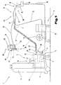
- 1, 2 and 3 is a welding system or a welding device 1 for various Welding processes such as MIG / MAG welding or TIG welding or electrode welding processes shown with or without a protective gas atmosphere.
- Welding processes such as MIG / MAG welding or TIG welding or electrode welding processes shown with or without a protective gas atmosphere.
- a power source or a welding power source can be used.
- the welding device 1 comprises a power source 2 with a power unit 3, a control device 4 and a switching element 5 assigned to the power unit 3 or the control device 4.
- the switching element 5 or the control device 4 is connected to a control valve 6, which in a supply line 7 for a gas 8, in particular a protective gas, such as CO 2 , helium or argon and the like, is arranged between a gas storage device 9 and a welding torch 10.
- a wire feed device 11 which, for example, can also be controlled via the control device 4 for which MIG / MAG welding is common, can be controlled, with a Supply line 12 a welding wire 13 from a storage drum 14 in the area of Welding torch 10 is supplied.
- the current to build an arc 15 between the welding wire 13 and one Workpiece 16 is passed from power unit 3 to welding torch 10 via a welding line 17 or the welding wire 13, wherein the workpiece 16 to be welded via a further welding line 18 also with the welding device 1, in particular with the power unit 3, is connected and thus a circuit can be set up over the arc 15 can.
- the welding torch can be cooled 19 10 with the interposition of a flow switch 20 with a liquid container, in particular a water tank 21, are connected, whereby when starting up the Welding torch 10 of the cooling circuit 19, in particular one for those in the water tank 21 arranged liquid used liquid pump is started and thus cooling of the welding torch 10 or the welding wire can be effected.
- a flow switch 20 with a liquid container, in particular a water tank 21, are connected, whereby when starting up the Welding torch 10 of the cooling circuit 19, in particular one for those in the water tank 21 arranged liquid used liquid pump is started and thus cooling of the welding torch 10 or the welding wire can be effected.
- the welding device 1 also has an input and / or output device 22 via which the different welding parameters or operating modes of the welding device 1 are set can be. In this case, those set via the input and / or output device 22 are set Welding parameters are forwarded to the control device 4 and are subsequently used by the latter the individual components of the welding system or the welding device 1 are controlled.
- Hose package 23 connected to the welding device 1 or the welding system.
- Hose package 23 are the individual lines from welding device 1 to welding torch 10 arranged.
- the hose package 23 is connected via a connecting device which is part of the prior art 24 connected to the welding torch 10, whereas the individual lines in the hose package 23 with the individual contacts of the welding device 1 via connection sockets or plug connections are connected.
- a corresponding strain relief of the hose package 23 is guaranteed, the hose package 23 is via a strain relief device 25 with a housing 26, in particular with the basic housing of the welding device 1, connected.
- a welding process can be started by the user or welder, is on Welding torch 10 arranged a start switch 27, i.e. that by activating the start switch 27 a signal is generated by the welder, which is sent via at least one line the control device 4 is forwarded. so that the control device 4 can recognize that a welding process and thus an ignition of the arc should be started and thus all necessary process steps, such as starting a gas flow, ignition of the arc, the activation of the wire feeder 11, etc., by the control device 4 can be initiated.
- These individual process steps are already state of the art Technology known and are therefore no longer described in detail, of course it is possible that the start switch 27 on the input and / or output device 22 or additionally can be arranged on this.
- the welder provides a corresponding protective device 28, in particular a protective screen 29 is used which, as already known from the prior art, on Head of the welder can be attached via a support member 30 or via a handle is held in front of the face, especially the eyes.
- the protective device 28 an electrically controllable protective visor 31 with a control device 32, i.e. the protective visor 31 by applying energy, in particular current and voltage, a darkening of the protective visor 31 is caused and thus the user the light intensity of the arc 15 is protected, as is already known.
- the control device 4 directs a control method for a welding system with the Welding device 1 and the protective device 28, in particular the protective screen 29 for the User, by operating the start switch 27, for example on the welding torch 10 or the welding device 1 a start signal to the control device 4 of the welding device or a power source for activating a welding process, wherein at the activation of the start switch 27 a signal or radio signal or a start command a transmitting and / or receiving device 33 and 34 to the control device 32 of FIG Protection device 28 is sent, whereupon from the control device 32 an electrical controllable and / or adjustable protective visor is activated by applying energy and then the welding process, in particular the ignition of the arc, preferably after Expiry of a pre-settable lead time and / or a gas lead time in which the blackout of the protective visor is started.
- a light-sensitive sensor is connected to the control device 32, so that due to the ignition of the arc 15, the sensor is activated by the high light intensity is sent and a signal to the control device 32, which then a corresponding Energy applied to the protective visor 31.
- the protective device 28 has a transmitting and / or receiving device 33, which is connected to the control device 32.
- the sending and / or receiving device 33 is with the welding system or the welding machine 1 or the welding torch 10 for example via a connecting line 35, as schematically with the Welding torch 10 shown, or connected wirelessly, wherein for sending a Signal to the transmitting and / or receiving device 33, the connecting line 35 directly or indirectly, in particular via a fieldbus, to the control device 4.
- the Transmitting and / or receiving device 33 for receiving radio signals 36 via electromagnetic Waves or optically, preferably via infrared signals.
- At least one component in particular the welding device 1, has another compatible transmitting and / or receiving device 34, as dashed in the basic housing 26 shown, so that a corresponding data exchange or transmission of a Radio signal 36 or control signal can be performed.
- a Radio signal 36 or control signal can be performed.
- both systems that is, the wired and wireless connection so that the welder can choose the type of connection.
- an energy source 37 in particular a battery and / or Solar cell, arranged, this for driving the protective visor 31 with energy is also taken from the energy source 37.
- a signal or start command is sent to the control device 4, whereupon the Control device 4, the individual start procedures are activated.
- the control device 4 controls the control valve 6, so that within a preset Gas lead time a protective gas atmosphere 38 around the welding wire 13 on the welding torch 10 is built up.
- the control device 4 a radio signal 36 or a control signal via the transmitting and / or receiving device 33 and 34 are sent to the control device 32, whereby the control device 32 the darkening process for the protective visor 31 is activated, i.e. that of the control device 32 an application of energy to the protective visor 31 is initiated.
- the protective visor 31 By simultaneously activating the gas lead time and the darkening process for The protective visor 31 is now ensured that before the arc 15 is ignited A darkening of the protective visor 31 is already ensured and therefore no consequential damage can arise for the welder, as is the case with the blackout process from the State of the art is the case.
- the lead time and / or the gas lead time is set so that for the darkening of the protective visor 31 different times Are available and thus it is always ensured that before the ignition of the arc 15 the darkening of the protective visor 31 is completed.
- the welding process ie the ignition of the Arc 15 initiated.
- the welder ends the welding process, i.e. the arc 15 is ended, this is recognized by the control device 4, so that a new one Signal or radio signal 36 or start command to deactivate the protective visor 31 on the control device 32 is sent, whereupon the energy supply to the Protective visor 31 is interrupted and thus the darkening of the protective visor 31 is canceled becomes.
- the protective device 28 in particular the protective screen 29 or a protective covers arranged on a welding robot or automatic welding machine in the Protective screen 29 and / or with the support frame 30 an image forming device 39 is arranged or connected, which is a data and / or image display 40 of adjustable Generates welding parameters and / or welding process images in the area of the protective visor 31, as is known from DE 40 37 879 A1 dealt with in the introduction to the description.
- a data and / or image display 40 of adjustable Generates welding parameters and / or welding process images in the area of the protective visor 31, as is known from DE 40 37 879 A1 dealt with in the introduction to the description.
- the welding parameters of the welding current 41 and Wire feed speed 42 shown.
- it is possible that several Welding parameters can be displayed.
- the protective device 28 only with the image forming device 39 and the energy source 37 is equipped, this in turn a wireless and / or wired connection with a component of the welding system or the welding device 1 can be connected.
- the image generating device 39 can in turn be connected to the transmitting and / or receiving device 34 and the energy source 37, which come from the battery and / or from the protective visor 31 arranged solar cells is formed, or connected to the control device 32.
- the virtual image is by displaying on the welding machine 1 or on the welding system or welding input of another input device, i.e. that of the Control device 4 these welding parameters via the transmitting and / or receiving devices 33 and 34 are transmitted to the protective device 28 and then to the image forming device 39 are forwarded so that a corresponding virtual Image, for example, by the setpoints and / or actual values of the Welding parameters is formed, can be displayed.
- the structure of the virtual image can be done arbitrarily, since each image generation device known from the prior art 39 can be used.
- a method for displaying data or images, in particular welding parameters, on the protective device 28, in particular the protective screen 29, in the case of a User or welder via the input and / or output device 22 on the welding system or the welding device 1 has individual welding parameters set for a welding process are carried out, with the transmitting and / or receiving device arranged in the welding device 1 34 data from at least one specified welding parameter to the other in the protective device 28, in particular the protective screen 29 or a protective cover, arranged transmitting and / or receiving device 33 are transmitted, which then transfers this data to the image forming device 39, whereupon the latter Data and / or image display 40 shows the welding parameters and / or a welding process image the protection device 28 generated.
- a video camera or other optical in the protective screen Recording device 43 which is positioned in this way is that this covers the field of vision of the protective visor 31 from the user or welder and thus a corresponding image 44 of the environment or the welding process in real time generated and forwarded to the image forming device 39.
- a Another virtual image 44 with the data from the video camera or the optical recording device 43 are formed in the area of the protective visor 31, so that, for example, the protective visor 31 can be made opaque, since a via the optical recording device 43 corresponding image 44 is generated, which is generated by the virtual image generating device 39 is made visible to the welder.
- This configuration of the protective device 28 for generating a virtual data and / or image display 40 in the area of protective visor 31 is advantageously achieved, that with a darkened protective visor 31 the user the most important welding parameters can recognize at any time and thus increases the welding quality of the weld bead formed there is always an intervention in the welding process by recognizing deviations is possible.
- adjusting members 45 are arranged so that a change in the welding parameters is possible without interrupting the welding process.
- the adjusting elements 45 designed in such a way that they match the welding parameters displayed, i.e. that at least one adjusting member 45 is arranged on the welding torch 10, for example which can adjust any welding parameter.
- this setting member 45 is shown by the control device 4 depending on the length Welding parameters set on the protective screen 29 so that by actuating the setting member 45 the setpoint of the welding parameter is changed, which is transmitted in real time to the image forming device 39 and thus the Welder can read the change made.
- a plurality of adjusting members 45 can be arranged, or that one adjusting member 45 and one Switching element for selecting the different welding parameters is arranged. In order to is achieved in an advantageous manner that a compact structure is achieved and at the same time any selection of setting options is created.
- control parameter 4 transmits these welding parameters to the image forming device 39 sent for display on the protective screen 29, so that the welder now the new welding parameter, in particular its actual or target value, and one for can recognize and read the short description stored in the welding parameter.
- the position of the display for the welding parameters by the user or welder is freely determined, i.e. that, as is known from the prior art, the welder, for example, via setting elements on the protective screen 29 or by simple means Touching the protective visor 31 determine the position where the virtual image is to be displayed can and thus, for example, the virtual image from the image generation device 39 44 is generated in the area of the user's eyes, the virtual image 44 of the data and / or Image display 40 on the welding device 1, in particular the individual ones to be displayed Welding parameters, freely selectable.
- the in the protective shield 31 integrated video camera or the optical recording device 43 of which a continuous Figure 44, in particular a welding image from the welding process and forwarded to the imaging device 39, whereupon from the imaging device 39 another image 44 is generated in the area of the eyes.
- a continuous Figure 44 in particular a welding image from the welding process and forwarded to the imaging device 39, whereupon from the imaging device 39 another image 44 is generated in the area of the eyes.
- one or more imaging devices 39 several virtual images on the protective device 28, in particular in the area of the Protective visors 31 are generated.
Landscapes
- Engineering & Computer Science (AREA)
- Physics & Mathematics (AREA)
- Mechanical Engineering (AREA)
- Plasma & Fusion (AREA)
- Health & Medical Sciences (AREA)
- Heart & Thoracic Surgery (AREA)
- Vascular Medicine (AREA)
- Animal Behavior & Ethology (AREA)
- General Health & Medical Sciences (AREA)
- Public Health (AREA)
- Veterinary Medicine (AREA)
- Theoretical Computer Science (AREA)
- Life Sciences & Earth Sciences (AREA)
- Biomedical Technology (AREA)
- Ophthalmology & Optometry (AREA)
- Arc Welding Control (AREA)
- Numerical Control (AREA)
- Road Signs Or Road Markings (AREA)
- Control Of Indicators Other Than Cathode Ray Tubes (AREA)
Description
- Fig. 1
- ein Schaubild einer Schweißmaschine bzw. eines Schweißgerätes mit einer erfindungsgemäßen Schutzvorrichtung, in vereinfachter, schematischer Darstellung;
- Fig. 2
- ein weiteres Schaubild der Schweißanlage mit der erfindungsgemäßen Schutzvorrichtung, in vereinfachter, schematischer Darstellung;
- Fig. 3
- ein Schaubild aus Sicht eines Schweißers durch die erfindungsgemäße Schützvorrichtung, in vereinfachter, schematischer Darstellung.
- 1
- Schweißgerät
- 2
- Stromquelle
- 3
- Leistungsteil
- 4
- Steuervorrichtung
- 5
- Umschaltglied
- 6
- Steuerventil
- 7
- Versorgungsleitung
- 8
- Gas
- 9
- Gasspeicher
- 10
- Schweißbrenner
- 11
- Drahtvorschubgerät
- 12
- Versorgungsleitung
- 13
- Schweißdraht
- 14
- Vorratstrommel
- 15
- Lichtbogen
- 16
- Werkstück
- 17.
- Schweißleitung
- 18
- Schweißleitung
- 19
- Kühlkreislauf
- 20
- Strömungswächter
- 21
- Wasserbehälter
- 22
- Ein- und/oder Ausgabevorrichtung
- 23
- Schlauchpaket
- 24
- Verbindungsvorrichtung
- 25
- Zugentlastungsvorrichtung
- 26
- Gehäuse
- 27
- Startschalter
- 28
- Schutzvorrichtung
- 29
- Schutzschirm
- 30
- Traggestell
- 31
- Schutzvisier
- 32
- Ansteuervorrichtung
- 33
- Sende- und/oder Empfangsvorrichtung
- 34
- Sende- und/oder Empfangsvorrichtung
- 35
- Verbindungsleitung
- 36
- Funksignal
- 37
- Energiequelle
- 38
- Schutzgasatmosphäre
- 39
- Bilderzeugungsvorrichtung
- 40
- Daten- und/oder Bildanzeige
- 41
- Schweißstrom
- 42
- Drahtvorschubgeschwindigkeit
- 43
- Aufnahmegerät
- 44
- Bild
- 45
- Einstellorgan
Claims (25)
- Schweißanlage mit einem Schweißgerät (1) und einer Schutzvorrichtung (28), insbesondere einem Schutzschirm (29) für einen Benutzer bzw. Schweißer, wobei die Schutzvorrichtung ein elektrisch steuer- und/oder regelbares Schutzvisier (31) mit einer Ansteuervorrichtung (32) aufweist, und das Schweißgerät bzw. die Schweißanlage zumindest durch eine Stromquelle, einen Schweißbrenner (10) und eine Steuervorrichtung (4) gebildet ist, dadurch gekennzeichnet, daß die Schutzvorrichtung (28) eine Sende- und/oder Empfangsvorrichtung (33) aufweist, welche mit der Ansteuervorrichtung (32) verbunden ist, wobei die Sende- und/oder Empfangsvorrichtung (33) mit der Schweißanlage oder dem Schweißgerät (1) oder dem Schweißbrenner (10) über eine Verbindungsleitung (34) oder drahtlos verbunden ist und daß die Steuervorrichtung (4) oder der Schweißbrenner (10) bei Aktivieren eines am Schweißbrenner (10) oder am Schweißgerät (1) angeordneten Startschalters (27) oder durch einen Startbefehl ein Signal über die Sende- und/oder Empfangsvorrichtung (33) an die Ansteuervorrichtung (32) zum Verdunkeln des Schutzvisiers (31) aussendet.
- Schweißanlage nach Anspruch 1, dadurch gekennzeichnet, daß die Steuervorrichtung (4) oder der Schweißbrenner (10) in Abhängigkeit der voreingestellten Schweißparameter, insbesondere eines Schweißstromes, unterschiedliche Signale bzw. Funksignale (36) an die Ansteuervorrichtung (32) übersendet, wobei durch das übersendete Signal bzw. das Funksignal (36) die Ansteuervorrichtung (32) den Verdunklungsgrad für das Schutzvisier (31) festlegt.
- Schweißanlage nach Anspruch 1 oder 2, dadurch gekennzeichnet, daß in der Schutzvorrichtung (28) eine Energiequelle (37), insbesondere eine Batterie oder eine Solarzelle, angeordnet ist.
- Schweißanlage nach einem oder mehreren der vorhergehenden Ansprüche, dadurch gekennzeichnet, daß die Steuervorrichtung (4) oder der Schweißbrenner (10) bei Beendigung des Schweißprozesses ein neuerliches Signal bzw. Funksignal oder einen Startbefehl über die Sende- und/oder Empfangsvorrichtung (33) an die Ansteuervorrichtung (32) zum Deaktivieren des Schutzvisiers (31) aussendet.
- Schweißanlage nach einem oder mehreren der vorhergehenden Ansprüche, dadurch gekennzeichnet, daß im Schutzschirm (29) und/oder auf einem Traggestell (30) eine Bilderzeugungsvorrichtung (39) angeordnet oder verbunden ist, welches eine Daten- und/oder Bildanzeige (40) von zumindest einem einstellbaren Schweißparameter und/oder ein Schweißprozeßbild im Bereich des Schutzvisiers (31) erzeugt.
- Schweißanlage nach Anspruch 5, dadurch gekennzeichnet, daß die Bilderzeugungsvorrichtung (39) mit einer Sende- und/oder Empfangsvorrichtung (33) und einer Energiequelle (37) verbunden ist.
- Schweißanlage nach Anspruch 6, dadurch gekennzeichnet, daß die Energiequelle (37) beispielsweise aus einer Batterie und/oder aus an dem Schutzschirm (29) angeordneten Solarzellen gebildet ist.
- Schweißanlage nach einem oder mehreren der vorhergehenden Ansprüche, dadurch gekennzeichnet, daß die Sende- und/oder Empfangsvorrichtung (33) drahtlos oder über eine Verbindungsleitung (34) mit einer weiteren in einem Schweißgerät (1) oder einem Schweißbrenner (10) angeordneten Sende- und/oder Empfangsvorrichtung (36) verbunden ist.
- Schweißanlage nach einem oder mehreren der vorhergehenden Ansprüche 5 mit 7, dadurch gekennzeichnet, daß das von der Bilderzeugungsvorrichtung (39) erzeugte virtuelle Bild (44) bzw. eine Daten- und/oder Bildanzeige (40) einen Teilbereich des Schutzvisiers (31) ausbildet.
- Schweißanlage nach einem oder mehreren der vorhergehenden Ansprüche 5 mit 7 oder 9, dadurch gekennzeichnet, daß das virtuelle Bild (44) der Daten- und/oder Bildanzeige (40) an dem Schweißgerät (1) frei auswählbar ist.
- Schweißanlage nach einem oder mehreren der vorhergehenden Ansprüche 5 mit 7 oder 9 mit 10, dadurch gekennzeichnet, daß das virtuelle Bild (44) bzw. die Datenund/oder Bildanzeige (40) durch die eingestellten Sollwerte und/oder Istwerte der Schweißparameter gebildet ist.
- Schweißanlage nach einem oder mehreren der vorhergehenden Ansprüche 5 mit 7 oder 9 mit 11, dadurch gekennzeichnet, daß im Schutzschirm (29) eine Videokamera oder ein anderes optisches Aufnahmegerät (43) angeordnet ist, welches derartig positioniert ist, daß dieses den Sichtbereich des Schutzvisiers (31) vom Benutzer abdeckt und ein entsprechendes Bild (44) in Echtzeit erzeugt und an die Bilderzeugungsvorrichtung (39) weiterleitet, welche ein weiteres virtuelles Bild (44) mit den Daten der Videokamera oder des optischen Aufnahmegerätes (43) im Bereich des Schutzvisiers (31) ausbildet.
- Schweißanlage nach einem oder mehreren der vorhergehenden Ansprüche 5 mit 7 oder 9 mit 12, dadurch gekennzeichnet, daß die Schutzvorrichtung (28) derartig ausgebildet ist, daß diese bei einem Schweißroboter als Schutzabdeckung einsetzbar ist.
- Steuerverfahren für eine Schweißanlage mit einem Schweißgerät (1) und einer Schutzvorrichtung (28), insbesondere einem Schutzschirm (29) für einen Benutzer, bei dem durch Betätigen eines Startschalters (27) an einem Schweißbrenner (10) oder einem Schweißgerät ein Startsignal an eine Steuervorrichtung (4) des Schweißgerätes oder einer Stromquelle zum Aktivieren eines Schweißprozesses erzeugt wird, dadurch gekennzeichnet, daß bei der Aktivierung des Startschalters (27) ein Startsignal oder Startbefehl über eine Sende- und/oder Empfangsvorrichtung (33) an eine Ansteuervorrichtung (32) der Schutzvorrichtung (28) übersandt wird, worauf von der Ansteuervorrichtung ein elektrisch steuer- und/oder regelbares Schutzvisier (31) durch Anlegen von Energie aktiviert wird und anschließend der Schweißprozeß, insbesondere die Zündung eines Lichtbogens, gestartet wird.
- Steuerverfahren nach Anspruch 14, dadurch gekennzeichnet, daß der Schweißprozeß, insbesondere die Zündung des Lichtbogens erst nach Ablauf einer voreinstellbaren Vorlaufzeit und/oder einer Gasvorlaufzeit, in der die Verdunkelung des Schutzvisiers erfolgt, gestartet wird.
- Steuerverfahren nach Anspruch 14 oder 15, dadurch gekennzeichnet, daß in Abhängigkeit der eingestellten Schweißparameter von der Steuervorrichtung die Vorlaufzeit und/oder die Gasvorlaufzeit festgelegt wird.
- Steuerverfahren nach einem oder mehreren der Ansprüche 14 bis 16, dadurch gekennzeichnet, daß der Verdunkelungsgrad des Schutzvisiers in Abhängigkeit der eingestellten Schweißparameter festgelegt wird, wobei von der Steuervorrichtung ein entsprechendes Signal an die Schutzvorrichtung übersandt wird.
- Steuerverfahren nach einem oder mehreren der Ansprüche 14 bis 17, dadurch gekennzeichnet, daß bei Beendigung des Schweißprozesses, also beim Erlöschen des Lichtbogens, ein neuerliches Signal bzw. Funksignal oder ein Startbefehl von der Steuervorrichtung ausgesandt wird, worauf von der Ansteuervorrichtung die Energiezufuhr an das Schutzvisier unterbrochen wird.
- Steuerverfahren nach einem oder mehreren der Ansprüche 14 bis 18, dadurch gekennzeichnet, daß von einer in dem Schweißgerät angeordneten Sende- und/oder Empfangsvorrichtung Daten von zumindest einem festgelegten Schweißparameter an eine weitere in einer Schutzvorrichtung, insbesondere einem Schutzschirm oder einer Schutzabdeckung, angeordneten Sende- und/oder Empfangsvorrichtung übersendet werden, die anschließende diese Daten an eine Bilderzeugungsvorrichtung übergibt, worauf von dieser eine Daten- und/oder Bildanzeige des Schweißparameters und/oder eines Schweißprozeßbildes an der Schutzvorrichtung erzeugt wird
- Steuerverfahren nach einem oder mehreren der Ansprüche 14 bis 19, dadurch gekennzeichnet, daß ein kontinuierlicher oder periodischer Datentransfer zwischen der Schweißanlage bzw. dem Schweißgerät und der Schutzvorrichtung bzw. dem Schutzschirm oder umgekehrt durchgeführt wird.
- Steuerverfahren nach einem oder mehreren der Ansprüche 19 bis 20, dadurch gekennzeichnet, daß vom Benutzer die anzuzeigenden Schweißparameter über die Ein- und/oder Ausgabevorrichtung oder über eine weitere Eingabevorrichtung festgelegt werden.
- Steuerverfahren nach einem oder mehreren der Ansprüche 19 bis 21, dadurch gekennzeichnet, daß die Position der Anzeige für die Schweißparameter vom Benutzer frei festgelegt wird.
- Steuerverfahren nach einem oder mehreren der Ansprüche 19 bis 22, dadurch gekennzeichnet, daß von der Bilderzeugungsvorrichtung ein virtuelles Bild im Bereich der Augen des Benutzers erzeugt wird.
- Steuerverfahren nach einem oder mehreren der Ansprüche 19 bis 23, dadurch gekennzeichnet, daß von einer im Schutzschild integrierter Videokamera oder optischen Aufnahmegerät ein kontinuierliches Bild aufgenommen wird, welches an die Bilderzeugungsvorrichtung weitergeleitet wird, worauf von der Bilderzeugungsvorrichtung ein weiteres Bild im Bereich der Augen erzeugt wird.
- Steuerverfahren nach einem oder mehreren der Ansprüche 19 bis 24, dadurch gekennzeichnet, daß von einer oder mehreren Bilderzeugungsvorrichtungen mehrere virtuelle Bilder an der Schutzvorrichtung erzeugt werden.
Applications Claiming Priority (3)
| Application Number | Priority Date | Filing Date | Title |
|---|---|---|---|
| AT139999 | 1999-08-13 | ||
| AT139999 | 1999-08-13 | ||
| PCT/AT2000/000219 WO2001012376A1 (de) | 1999-08-13 | 2000-08-11 | Datenanzeige am schweissschirm |
Publications (3)
| Publication Number | Publication Date |
|---|---|
| EP1202832A1 EP1202832A1 (de) | 2002-05-08 |
| EP1202832B1 true EP1202832B1 (de) | 2004-06-23 |
| EP1202832B2 EP1202832B2 (de) | 2007-01-03 |
Family
ID=3513048
Family Applications (1)
| Application Number | Title | Priority Date | Filing Date |
|---|---|---|---|
| EP00954155A Expired - Lifetime EP1202832B2 (de) | 1999-08-13 | 2000-08-11 | Datenanzeige am schweissschirm |
Country Status (9)
| Country | Link |
|---|---|
| US (1) | US6734393B1 (de) |
| EP (1) | EP1202832B2 (de) |
| AT (1) | ATE269774T1 (de) |
| AU (1) | AU6670800A (de) |
| DE (1) | DE50006896D1 (de) |
| DK (1) | DK1202832T4 (de) |
| ES (1) | ES2223563T5 (de) |
| PT (1) | PT1202832E (de) |
| WO (1) | WO2001012376A1 (de) |
Families Citing this family (152)
| Publication number | Priority date | Publication date | Assignee | Title |
|---|---|---|---|---|
| WO2005002481A1 (en) * | 2003-07-02 | 2005-01-13 | Lightswitch Safety Systems, Inc. | Indicator layout on an auto-darkening lens for use in welding |
| US7161135B2 (en) * | 2003-07-03 | 2007-01-09 | Lightswitch Safety Systems, Inc. | Multi-stage sensor for an auto-darkening lens for use in welding and method |
| AT500532B1 (de) * | 2004-03-09 | 2009-07-15 | Fronius Int Gmbh | Schweissgerätesteuerung |
| US8546728B2 (en) | 2005-03-04 | 2013-10-01 | Illinois Tool Works Inc. | Welder with integrated wire feeder having single-knob control |
| AT502327B1 (de) * | 2005-08-30 | 2009-07-15 | Fronius Inernat Gmbh | Verfahren zum steuern eines schutzvisiers |
| US7637622B2 (en) * | 2005-10-11 | 2009-12-29 | 3M Innovative Properties Company | Control of an automatic darkening filter |
| EP1951888B1 (de) * | 2005-11-09 | 2012-09-05 | PrimeraDx, Inc. | Multiplexierte quantitative erkennung von krankheitserregern |
| US10994358B2 (en) | 2006-12-20 | 2021-05-04 | Lincoln Global, Inc. | System and method for creating or modifying a welding sequence based on non-real world weld data |
| US9104195B2 (en) | 2006-12-20 | 2015-08-11 | Lincoln Global, Inc. | Welding job sequencer |
| US9937577B2 (en) | 2006-12-20 | 2018-04-10 | Lincoln Global, Inc. | System for a welding sequencer |
| DE102007036505A1 (de) * | 2007-08-01 | 2009-02-12 | Ewm Hightec Welding Gmbh | Verfahren , Vorrichtung und System zur Ermittlung einer Schweißgeschwindigkeit bei einem manuell ausgeführten Lichtbogenschweißvorgang |
| GB2454232B (en) * | 2007-11-01 | 2012-04-25 | Validation Ct Tvc Ltd | Welding support system |
| US8502866B2 (en) * | 2008-03-14 | 2013-08-06 | Illinois Tool Works Inc. | Video recording device for a welder's helmet |
| WO2009146359A1 (en) | 2008-05-28 | 2009-12-03 | Illinois Tool Works Inc. | Welding training system |
| US8884177B2 (en) | 2009-11-13 | 2014-11-11 | Lincoln Global, Inc. | Systems, methods, and apparatuses for monitoring weld quality |
| US9318026B2 (en) | 2008-08-21 | 2016-04-19 | Lincoln Global, Inc. | Systems and methods providing an enhanced user experience in a real-time simulated virtual reality welding environment |
| US9330575B2 (en) | 2008-08-21 | 2016-05-03 | Lincoln Global, Inc. | Tablet-based welding simulator |
| US9280913B2 (en) | 2009-07-10 | 2016-03-08 | Lincoln Global, Inc. | Systems and methods providing enhanced education and training in a virtual reality environment |
| US8851896B2 (en) | 2008-08-21 | 2014-10-07 | Lincoln Global, Inc. | Virtual reality GTAW and pipe welding simulator and setup |
| US9196169B2 (en) | 2008-08-21 | 2015-11-24 | Lincoln Global, Inc. | Importing and analyzing external data using a virtual reality welding system |
| US9483959B2 (en) | 2008-08-21 | 2016-11-01 | Lincoln Global, Inc. | Welding simulator |
| KR20100041287A (ko) * | 2008-10-14 | 2010-04-22 | 오토스테크 주식회사 | 기능성 디스플레이 눈부심 방지 장치 |
| US8274013B2 (en) | 2009-03-09 | 2012-09-25 | Lincoln Global, Inc. | System for tracking and analyzing welding activity |
| AT508094B1 (de) | 2009-03-31 | 2015-05-15 | Fronius Int Gmbh | Verfahren und vorrichtung zur bedienung einer mit einem handbetätigten arbeitsgerät verbundenen stromquelle |
| US9221117B2 (en) | 2009-07-08 | 2015-12-29 | Lincoln Global, Inc. | System for characterizing manual welding operations |
| US9773429B2 (en) | 2009-07-08 | 2017-09-26 | Lincoln Global, Inc. | System and method for manual welder training |
| US10748447B2 (en) | 2013-05-24 | 2020-08-18 | Lincoln Global, Inc. | Systems and methods providing a computerized eyewear device to aid in welding |
| US9011154B2 (en) | 2009-07-10 | 2015-04-21 | Lincoln Global, Inc. | Virtual welding system |
| IT1398630B1 (it) * | 2009-07-30 | 2013-03-08 | Tecnoelettra Spa | Torcia saldante ad arco del tipo mig o mag |
| US20150209887A1 (en) * | 2009-10-13 | 2015-07-30 | Lincoln Global, Inc. | Welding helmet with heads up display |
| US20170173720A1 (en) * | 2009-10-13 | 2017-06-22 | Lincolng Global, Inc. | Welding helmet with heads up display and voice command |
| US8569655B2 (en) * | 2009-10-13 | 2013-10-29 | Lincoln Global, Inc. | Welding helmet with integral user interface |
| US8569646B2 (en) | 2009-11-13 | 2013-10-29 | Lincoln Global, Inc. | Systems, methods, and apparatuses for monitoring weld quality |
| US9468988B2 (en) | 2009-11-13 | 2016-10-18 | Lincoln Global, Inc. | Systems, methods, and apparatuses for monitoring weld quality |
| KR101130222B1 (ko) * | 2009-12-24 | 2012-03-29 | 주식회사 오토스윙 | 용접 헬멧의 카트리지 제어방법 |
| US20110220616A1 (en) * | 2010-03-10 | 2011-09-15 | Illinois Tool Works Inc. | Welding device with integral user interface |
| CA2821671C (en) | 2010-12-13 | 2018-01-09 | Edison Welding Institute, Inc. | Welding training system |
| CA2830995C (en) | 2011-03-25 | 2019-05-14 | Illinois Tool Works Inc. | Welding systems with means for adjust and displaying ranges of parameters for setting the latter; method of setting such welding parameters |
| US20120286958A1 (en) * | 2011-05-12 | 2012-11-15 | Lincoln Global, Inc. | Welding helmet configuration providing real-time fume exposure warning capability |
| US9101994B2 (en) | 2011-08-10 | 2015-08-11 | Illinois Tool Works Inc. | System and device for welding training |
| US9573215B2 (en) | 2012-02-10 | 2017-02-21 | Illinois Tool Works Inc. | Sound-based weld travel speed sensing system and method |
| US20130288211A1 (en) * | 2012-04-27 | 2013-10-31 | Illinois Tool Works Inc. | Systems and methods for training a welding operator |
| US20160093233A1 (en) | 2012-07-06 | 2016-03-31 | Lincoln Global, Inc. | System for characterizing manual welding operations on pipe and other curved structures |
| US9767712B2 (en) | 2012-07-10 | 2017-09-19 | Lincoln Global, Inc. | Virtual reality pipe welding simulator and setup |
| US9119023B2 (en) | 2012-08-17 | 2015-08-25 | Illinois Tool Works Inc. | Wireless communication network association and security for control of industrial equipment in harsh environments |
| US9449498B2 (en) * | 2012-08-17 | 2016-09-20 | Illinois Tool Works Inc. | Wireless communication network power optimization for control of industrial equipment in harsh environments |
| US9270520B2 (en) | 2012-08-17 | 2016-02-23 | Illinois Tool Works Inc. | Wireless communication network sensor information for control of industrial equipment in harsh environments |
| US10286475B2 (en) * | 2012-08-17 | 2019-05-14 | Illinois Tool Works Inc. | Wireless communication network for control of industrial equipment in harsh environments |
| US9712947B2 (en) * | 2012-08-17 | 2017-07-18 | Illinois Tool Works Inc. | Wireless communication network improved robustness for control of industrial equipment in harsh environments |
| US10118241B2 (en) | 2012-09-07 | 2018-11-06 | Illinois Tool Works Inc. | Welding system with multiple user interface modules |
| US9368045B2 (en) | 2012-11-09 | 2016-06-14 | Illinois Tool Works Inc. | System and device for welding training |
| US9583014B2 (en) | 2012-11-09 | 2017-02-28 | Illinois Tool Works Inc. | System and device for welding training |
| ES2768613T3 (es) * | 2013-03-11 | 2020-06-23 | Lincoln Global Inc | Sistemas y métodos que proporcionan educación y formación potenciados en un entorno de realidad virtual |
| US9728103B2 (en) * | 2013-03-15 | 2017-08-08 | Illinois Tool Works Inc. | Data storage and analysis for a welding training system |
| US9672757B2 (en) | 2013-03-15 | 2017-06-06 | Illinois Tool Works Inc. | Multi-mode software and method for a welding training system |
| US9713852B2 (en) | 2013-03-15 | 2017-07-25 | Illinois Tool Works Inc. | Welding training systems and devices |
| US9666100B2 (en) | 2013-03-15 | 2017-05-30 | Illinois Tool Works Inc. | Calibration devices for a welding training system |
| US9583023B2 (en) | 2013-03-15 | 2017-02-28 | Illinois Tool Works Inc. | Welding torch for a welding training system |
| EP2799046A1 (de) | 2013-04-30 | 2014-11-05 | Optrel Ag | Vorrichtung und Verfahren zum Blendschutz |
| US10930174B2 (en) | 2013-05-24 | 2021-02-23 | Lincoln Global, Inc. | Systems and methods providing a computerized eyewear device to aid in welding |
| US11090753B2 (en) | 2013-06-21 | 2021-08-17 | Illinois Tool Works Inc. | System and method for determining weld travel speed |
| US20150072323A1 (en) * | 2013-09-11 | 2015-03-12 | Lincoln Global, Inc. | Learning management system for a real-time simulated virtual reality welding training environment |
| US10083627B2 (en) | 2013-11-05 | 2018-09-25 | Lincoln Global, Inc. | Virtual reality and real welding training system and method |
| US10056010B2 (en) | 2013-12-03 | 2018-08-21 | Illinois Tool Works Inc. | Systems and methods for a weld training system |
| US9724788B2 (en) | 2014-01-07 | 2017-08-08 | Illinois Tool Works Inc. | Electrical assemblies for a welding system |
| US9751149B2 (en) | 2014-01-07 | 2017-09-05 | Illinois Tool Works Inc. | Welding stand for a welding system |
| US9757819B2 (en) | 2014-01-07 | 2017-09-12 | Illinois Tool Works Inc. | Calibration tool and method for a welding system |
| US10105782B2 (en) | 2014-01-07 | 2018-10-23 | Illinois Tool Works Inc. | Feedback from a welding torch of a welding system |
| US9589481B2 (en) | 2014-01-07 | 2017-03-07 | Illinois Tool Works Inc. | Welding software for detection and control of devices and for analysis of data |
| US10170019B2 (en) | 2014-01-07 | 2019-01-01 | Illinois Tool Works Inc. | Feedback from a welding torch of a welding system |
| US9836987B2 (en) | 2014-02-14 | 2017-12-05 | Lincoln Global, Inc. | Virtual reality pipe welding simulator and setup |
| US20170021441A1 (en) * | 2014-04-04 | 2017-01-26 | Trafimet Group S.P.A. | Sensor for detecting/measuring the welding and/or cutting current in a welding and/or cutting system |
| WO2015151050A1 (en) * | 2014-04-04 | 2015-10-08 | Trafimet S.P.A. | Control system for welding systems |
| US10701270B1 (en) * | 2014-05-15 | 2020-06-30 | Thomas J. LaFlech | Camera display welder's helmet |
| WO2015185972A1 (en) | 2014-06-02 | 2015-12-10 | Lincoln Global, Inc. | System and method for manual welder training |
| WO2015185973A1 (en) * | 2014-06-02 | 2015-12-10 | Lincoln Global, Inc. | System for and method of monitoring and characterizing manual welding operations |
| US10307853B2 (en) | 2014-06-27 | 2019-06-04 | Illinois Tool Works Inc. | System and method for managing welding data |
| US9862049B2 (en) | 2014-06-27 | 2018-01-09 | Illinois Tool Works Inc. | System and method of welding system operator identification |
| US10665128B2 (en) | 2014-06-27 | 2020-05-26 | Illinois Tool Works Inc. | System and method of monitoring welding information |
| US9937578B2 (en) | 2014-06-27 | 2018-04-10 | Illinois Tool Works Inc. | System and method for remote welding training |
| US10285864B2 (en) | 2014-07-25 | 2019-05-14 | Snap-On Incorporated | Auto-darkening welding helmet |
| US9724787B2 (en) | 2014-08-07 | 2017-08-08 | Illinois Tool Works Inc. | System and method of monitoring a welding environment |
| US11014183B2 (en) | 2014-08-07 | 2021-05-25 | Illinois Tool Works Inc. | System and method of marking a welding workpiece |
| US9875665B2 (en) | 2014-08-18 | 2018-01-23 | Illinois Tool Works Inc. | Weld training system and method |
| US11103948B2 (en) | 2014-08-18 | 2021-08-31 | Illinois Tool Works Inc. | Systems and methods for a personally allocated interface for use in a welding system |
| CN107072818B (zh) | 2014-09-15 | 2020-03-13 | 3M创新有限公司 | 个人防护系统工具通信适配器 |
| US10446057B2 (en) | 2014-09-19 | 2019-10-15 | Realityworks, Inc. | Welding speed sensor |
| WO2016044680A1 (en) | 2014-09-19 | 2016-03-24 | Realityworks, Inc. | Welding speed pacing device |
| US11247289B2 (en) | 2014-10-16 | 2022-02-15 | Illinois Tool Works Inc. | Remote power supply parameter adjustment |
| US10239147B2 (en) | 2014-10-16 | 2019-03-26 | Illinois Tool Works Inc. | Sensor-based power controls for a welding system |
| US9922460B2 (en) | 2014-11-04 | 2018-03-20 | Illinois Tool Works Inc. | Stereoscopic helmet display |
| US10373304B2 (en) | 2014-11-05 | 2019-08-06 | Illinois Tool Works Inc. | System and method of arranging welding device markers |
| US10402959B2 (en) | 2014-11-05 | 2019-09-03 | Illinois Tool Works Inc. | System and method of active torch marker control |
| US10417934B2 (en) | 2014-11-05 | 2019-09-17 | Illinois Tool Works Inc. | System and method of reviewing weld data |
| US10204406B2 (en) | 2014-11-05 | 2019-02-12 | Illinois Tool Works Inc. | System and method of controlling welding system camera exposure and marker illumination |
| US10490098B2 (en) | 2014-11-05 | 2019-11-26 | Illinois Tool Works Inc. | System and method of recording multi-run data |
| US10210773B2 (en) | 2014-11-05 | 2019-02-19 | Illinois Tool Works Inc. | System and method for welding torch display |
| EP3223990A1 (de) * | 2014-11-27 | 2017-10-04 | Nuovo Pignone S.r.l. | Schweisshilfsvorrichtung mit einer schweissmaske mit geschwindigkeitssensor |
| CN104400186B (zh) * | 2014-11-27 | 2016-02-03 | 郭智峰 | 级联式电焊机电源拓扑结构 |
| US10032388B2 (en) | 2014-12-05 | 2018-07-24 | Illinois Tool Works Inc. | Augmented and mediated reality welding helmet systems |
| US10363627B2 (en) | 2014-12-16 | 2019-07-30 | Illinois Tool Works Inc. | Systems and methods for providing location services for a welding power supply |
| US10773329B2 (en) | 2015-01-20 | 2020-09-15 | Illinois Tool Works Inc. | Multiple input welding vision system |
| US20160207134A1 (en) * | 2015-01-20 | 2016-07-21 | Illinois Tool Works Inc. | Weld output control by a welding vision system |
| US10406638B2 (en) | 2015-02-27 | 2019-09-10 | Illinois Tool Works Inc. | Augmented vision system with active welder guidance |
| CN113192374B (zh) | 2015-03-06 | 2023-09-01 | 伊利诺斯工具制品有限公司 | 用于焊接的传感器辅助头戴式显示器 |
| CN107980153B (zh) | 2015-03-09 | 2021-10-22 | 伊利诺斯工具制品有限公司 | 提供与焊接操作相关联的视觉信息的方法和装置 |
| CN105982785B (zh) * | 2015-03-18 | 2021-04-06 | 泰克曼(南京)电子有限公司 | 无线投影式焊接面罩及配备其的焊接机 |
| US9977242B2 (en) | 2015-03-26 | 2018-05-22 | Illinois Tool Works Inc. | Control of mediated reality welding system based on lighting conditions |
| US9666160B2 (en) * | 2015-03-26 | 2017-05-30 | Illinois Tool Works Inc. | Control of mediated reality welding system based on lighting conditions |
| US10427239B2 (en) | 2015-04-02 | 2019-10-01 | Illinois Tool Works Inc. | Systems and methods for tracking weld training arc parameters |
| CN106038057A (zh) * | 2015-04-09 | 2016-10-26 | 林肯环球股份有限公司 | 具有平视显示器的焊工帽罩 |
| US10363632B2 (en) | 2015-06-24 | 2019-07-30 | Illinois Tool Works Inc. | Time of flight camera for welding machine vision |
| US10369652B2 (en) | 2015-07-24 | 2019-08-06 | Illinois Tool Works Inc. | Wireless and powerline communications in a welding-type system |
| US10373517B2 (en) * | 2015-08-12 | 2019-08-06 | Illinois Tool Works Inc. | Simulation stick welding electrode holder systems and methods |
| US10657839B2 (en) * | 2015-08-12 | 2020-05-19 | Illinois Tool Works Inc. | Stick welding electrode holders with real-time feedback features |
| US10593230B2 (en) * | 2015-08-12 | 2020-03-17 | Illinois Tool Works Inc. | Stick welding electrode holder systems and methods |
| US10438505B2 (en) | 2015-08-12 | 2019-10-08 | Illinois Tool Works | Welding training system interface |
| US9972215B2 (en) | 2015-08-18 | 2018-05-15 | Lincoln Global, Inc. | Augmented reality interface for weld sequencing |
| CA3005703A1 (en) * | 2015-12-07 | 2017-06-15 | Trafimet Group S.P.A. | Method and system for an accelerated reaction of darkening of the optical device in personal protective equipment |
| US10773328B2 (en) * | 2015-12-15 | 2020-09-15 | Illinois Tool Works Inc. | Welding system user interface having a color display for setting welding parameters |
| US10610708B2 (en) | 2016-06-23 | 2020-04-07 | 3M Innovative Properties Company | Indicating hazardous exposure in a supplied air respirator system |
| US9998804B2 (en) | 2016-06-23 | 2018-06-12 | 3M Innovative Properties Company | Personal protective equipment (PPE) with analytical stream processing for safety event detection |
| US9848666B1 (en) | 2016-06-23 | 2017-12-26 | 3M Innovative Properties Company | Retrofit sensor module for a protective head top |
| US11023818B2 (en) | 2016-06-23 | 2021-06-01 | 3M Innovative Properties Company | Personal protective equipment system having analytics engine with integrated monitoring, alerting, and predictive safety event avoidance |
| BR112018076865A2 (pt) * | 2016-06-23 | 2019-04-02 | 3M Innovative Properties Company | protetor auditivo com sensores de monitoramento de posição e som para evitar riscos sonoros proativos |
| US11260251B2 (en) | 2016-06-23 | 2022-03-01 | 3M Innovative Properties Company | Respirator device with light exposure detection |
| US20180015560A1 (en) * | 2016-07-14 | 2018-01-18 | Lincoln Global, Inc. | Method and system for welding with temperature detector |
| CN106112321A (zh) * | 2016-07-25 | 2016-11-16 | 柳州永旺科技有限公司 | 远程智能焊接系统 |
| EP3319066A1 (de) | 2016-11-04 | 2018-05-09 | Lincoln Global, Inc. | Magnetische frequenzwahl für elektromagnetische positionsverfolgung |
| US10878591B2 (en) | 2016-11-07 | 2020-12-29 | Lincoln Global, Inc. | Welding trainer utilizing a head up display to display simulated and real-world objects |
| US10913125B2 (en) | 2016-11-07 | 2021-02-09 | Lincoln Global, Inc. | Welding system providing visual and audio cues to a welding helmet with a display |
| EP3326592A1 (de) * | 2016-11-23 | 2018-05-30 | optrel Holding AG | Schutzkassette |
| WO2018200299A1 (en) * | 2017-04-26 | 2018-11-01 | Illinois Tool Works Inc. | Head-worn device with control of mediated reality welding system based on lighting conditions |
| US10997872B2 (en) | 2017-06-01 | 2021-05-04 | Lincoln Global, Inc. | Spring-loaded tip assembly to support simulated shielded metal arc welding |
| US11557223B2 (en) | 2018-04-19 | 2023-01-17 | Lincoln Global, Inc. | Modular and reconfigurable chassis for simulated welding training |
| US11475792B2 (en) | 2018-04-19 | 2022-10-18 | Lincoln Global, Inc. | Welding simulator with dual-user configuration |
| KR102071477B1 (ko) * | 2018-04-24 | 2020-01-30 | 주식회사 오토스윙 | 용접용 상태 알람 마스크 및 상태 알람 마스크의 동작 방법 |
| US20200114456A1 (en) * | 2018-10-10 | 2020-04-16 | Lincoln Global, Inc. | Systems and methods including a head-mounted device for use in arc welding |
| IT201800009774A1 (it) * | 2018-10-25 | 2020-04-25 | Trafimet Group Spa | Elmetto protettivo di saldatura o taglio ed impianto di saldatura o taglio provvisto di tale elmetto |
| CN109172136A (zh) * | 2018-10-29 | 2019-01-11 | 安徽华生机电设备有限公司 | 一种无线自动变光焊帽及其控制系统 |
| US11450233B2 (en) | 2019-02-19 | 2022-09-20 | Illinois Tool Works Inc. | Systems for simulating joining operations using mobile devices |
| US11521512B2 (en) | 2019-02-19 | 2022-12-06 | Illinois Tool Works Inc. | Systems for simulating joining operations using mobile devices |
| US11776423B2 (en) | 2019-07-22 | 2023-10-03 | Illinois Tool Works Inc. | Connection boxes for gas tungsten arc welding training systems |
| US11288978B2 (en) | 2019-07-22 | 2022-03-29 | Illinois Tool Works Inc. | Gas tungsten arc welding training systems |
| US11833625B2 (en) * | 2019-08-21 | 2023-12-05 | Illinois Tool Works Inc. | Welding asset tracking with heartbeat monitoring |
| US11721231B2 (en) | 2019-11-25 | 2023-08-08 | Illinois Tool Works Inc. | Weld training simulations using mobile devices, modular workpieces, and simulated welding equipment |
| US12198568B2 (en) | 2019-11-25 | 2025-01-14 | Illinois Tool Works Inc. | Weld training simulations using mobile devices, modular workpieces, and simulated welding equipment |
| US11322037B2 (en) | 2019-11-25 | 2022-05-03 | Illinois Tool Works Inc. | Weld training simulations using mobile devices, modular workpieces, and simulated welding equipment |
| US12100283B2 (en) * | 2020-07-30 | 2024-09-24 | 3M Innovative Properties Company | System and method for personal protective equipment |
| US20220079812A1 (en) * | 2020-09-16 | 2022-03-17 | Arcmask Optech Co., Ltd | Anti-glare welding apparatus |
| EP3970896A1 (de) * | 2020-09-17 | 2022-03-23 | Arcmask Optech Co., Ltd | Blendfreie schweissvorrichtung |
| CN112022504A (zh) * | 2020-10-09 | 2020-12-04 | 浙江浙能技术研究院有限公司 | 一种可追溯实时焊接工艺的头戴式焊接防护面罩 |
Family Cites Families (21)
| Publication number | Priority date | Publication date | Assignee | Title |
|---|---|---|---|---|
| US1822308A (en) * | 1930-11-05 | 1931-09-08 | John S Norton | Electrically operated welder's hood |
| US2761046A (en) * | 1953-02-16 | 1956-08-28 | Herrick James Elder | Automatic arc welding viewing mechanism |
| US3692974A (en) | 1970-10-26 | 1972-09-19 | James P Thomason | Automatic welding hood with automatically positioned eye shield |
| US3792226A (en) * | 1972-08-29 | 1974-02-12 | Us Army | Eye protector for welders |
| ATE27862T1 (de) † | 1982-04-14 | 1987-07-15 | Andre M Eggenschwiler | Lichtschutzfilter, insbesondere fuer schweissschutzschilder oder schweissschutzbrillen. |
| JPS6194654A (ja) | 1984-10-16 | 1986-05-13 | 長瀬産業株式会社 | 溶接におけるア−ク光の遮光方法および装置 |
| US4555614A (en) * | 1984-12-24 | 1985-11-26 | The United States Of America As Represented By The Secretary Of The Navy | Weld metal cooling rate indicator system |
| US4679255A (en) | 1986-03-06 | 1987-07-14 | Kuhlman Thomas E | Welder's mask with remote controlled eye shield |
| EP0331861A1 (de) * | 1988-03-11 | 1989-09-13 | Optrel Ag | Vorrichtung zur Steuerung der Transmission eines Lichtschutzfilters |
| US4882769A (en) * | 1988-07-05 | 1989-11-21 | Gallimore Bruce A | AM/FM radio with sunglass housing |
| GB2238627B (en) | 1989-11-29 | 1994-04-06 | Yazaki Corp | Display apparatus |
| DE4128291A1 (de) † | 1991-08-27 | 1993-03-04 | Optrel Ag | Lichtschutzfilter, mit einem bezueglich seiner optischen transmission elektrisch steuerbaren filterelement |
| US5377032A (en) * | 1993-02-05 | 1994-12-27 | Osd Envizion Company | Electro-optic light shutter and frame assembly with integrated switching mechanism |
| US5317643A (en) * | 1993-02-08 | 1994-05-31 | Patricelli Richard D | Audio helmet apparatus |
| DE4330817C1 (de) † | 1993-09-13 | 1994-12-01 | Optrel Ag | Verfahren zur Steuerung einer Blendschutzeinrichtung und Blendschutzeinrichtung zur Durchführung des Verfahrens |
| US5609782A (en) * | 1994-10-29 | 1997-03-11 | Hyundai Heavy Industries Co., Ltd. | Shielding gas pre-flow time control system for gas metal arc welder |
| JPH0998395A (ja) | 1995-09-29 | 1997-04-08 | Yokogawa Electric Corp | コミュニケーションヘルメット |
| DE19621664B4 (de) | 1996-01-22 | 2005-08-04 | Diehl Stiftung & Co.Kg | Steuereinheit für eine Heizungsanlage |
| DE29602946U1 (de) | 1996-02-20 | 1996-04-04 | JUPITER Schweiß-, reparatur- und wartungstechnische Produkte GmbH, 90587 Veitsbronn | Anlage zum elektrischen Lichtbogen-, insbesondere (MIG/MAG-) Schutzgas-Lichtbogenschweißen |
| FR2779635B1 (fr) | 1998-06-12 | 2000-09-22 | Soudure Autogene Francaise | Casque de soudage avec afficheur d'informations |
| ES2202029T3 (es) * | 1999-11-05 | 2004-04-01 | Ciba Specialty Chemicals Holding Inc. | Colorantes reactivos, procedimiento de obtencion y utilizacion de los mismos. |
-
2000
- 2000-08-11 US US10/049,389 patent/US6734393B1/en not_active Expired - Lifetime
- 2000-08-11 DE DE50006896T patent/DE50006896D1/de not_active Expired - Lifetime
- 2000-08-11 ES ES00954155T patent/ES2223563T5/es not_active Expired - Lifetime
- 2000-08-11 EP EP00954155A patent/EP1202832B2/de not_active Expired - Lifetime
- 2000-08-11 PT PT00954155T patent/PT1202832E/pt unknown
- 2000-08-11 AT AT00954155T patent/ATE269774T1/de active
- 2000-08-11 DK DK00954155T patent/DK1202832T4/da active
- 2000-08-11 WO PCT/AT2000/000219 patent/WO2001012376A1/de not_active Ceased
- 2000-08-11 AU AU66708/00A patent/AU6670800A/en not_active Abandoned
Also Published As
| Publication number | Publication date |
|---|---|
| DE50006896D1 (de) | 2004-07-29 |
| DK1202832T4 (da) | 2007-05-14 |
| DK1202832T3 (da) | 2004-09-27 |
| US6734393B1 (en) | 2004-05-11 |
| AU6670800A (en) | 2001-03-13 |
| ES2223563T3 (es) | 2005-03-01 |
| EP1202832B2 (de) | 2007-01-03 |
| ES2223563T5 (es) | 2007-09-16 |
| ATE269774T1 (de) | 2004-07-15 |
| PT1202832E (pt) | 2004-10-29 |
| EP1202832A1 (de) | 2002-05-08 |
| WO2001012376A1 (de) | 2001-02-22 |
Similar Documents
| Publication | Publication Date | Title |
|---|---|---|
| EP1202832B2 (de) | Datenanzeige am schweissschirm | |
| DE102011103282B4 (de) | Verfahren zum Überwachen der Bearbeitung sowie Vorrichtung zum Bearbeiten eines Werkstücks mit einem hochenergetischen Bearbeitungsstrahl | |
| EP2029073B1 (de) | Gesichts- und blendschutzvorrichtung für personen in arbeitsbereichen mit gefährlicher, schädlicher oder störender strahlung, insbesondere für schweisser | |
| DE69822063T2 (de) | Schweissroboterregeleinrichtung | |
| AT502378B1 (de) | Verfahren zur parameterselektion bei schweissgeräten | |
| DE102008053342B4 (de) | Schweißverfahren | |
| DE112009001076T5 (de) | Schweißcharakteristik-Kommunikationssystem für eine Schweißmaske | |
| AT8744U1 (de) | Verfahren zum betreiben einer schweissvorrichtung, schweissvorrichtung sowie schweissbrenner für eine solche schweissvorrichtung | |
| EP1047521A1 (de) | Steuervorrichtung für ein schweissgerät | |
| EP3650157B1 (de) | Orbitalschweissvorrichtung mit vereinfachter handhabung | |
| DE202012013133U1 (de) | Dualspektrum-Digitalbildgabe-Schweisshaube | |
| DE3828473A1 (de) | Mit stabelektroden arbeitender lichtbogen-schweissautomat und eine bevorzugte anwendung eines solchen | |
| DE102020206405A1 (de) | Schweißführungssystem | |
| EP2640542B1 (de) | Vorrichtung und verfahren zur überwachung eines lichtbogenprozesses | |
| EP3982895B1 (de) | Schweisshelm | |
| AT502327B1 (de) | Verfahren zum steuern eines schutzvisiers | |
| EP1549453B1 (de) | Abschaltbox für eine roboteranlage | |
| DE2933216A1 (de) | Verfahren und vorrichtung zur ueberwachung eines werkstuecks bei der bearbeitung durch elektrische entladung | |
| DE202016002243U1 (de) | Schweisshelm mit Head-Up-Display | |
| DE10297590T5 (de) | Fahrunterstützungssystem, Bildausgabevorrichtung und mit Kamera ausgestatteter Stab | |
| DE10332320A1 (de) | Verfahren und Vorrichtung zum Überprüfen von Schweißungen für Laser-Schweißgeräte | |
| DE102013216169B4 (de) | Vorrichtung zum Nachbearbeiten von Fehlstellen in der Bauteilfertigung sowie Verwenden der Vorrichtung | |
| DE4210555A1 (de) | Vorsatzoptik für eine Kamera | |
| DE60017723T2 (de) | Robotersteuerung mit einer Überwachungsfunktion der Anomalien | |
| DE102011122991B3 (de) | Verfahren zum Überwachen der Bearbeitung sowie Vorrichtung zum Bearbeiten eines Werkstücks mit einem hochenergetischen Bearbeitungsstrahl |
Legal Events
| Date | Code | Title | Description |
|---|---|---|---|
| PUAI | Public reference made under article 153(3) epc to a published international application that has entered the european phase |
Free format text: ORIGINAL CODE: 0009012 |
|
| 17P | Request for examination filed |
Effective date: 20020207 |
|
| AK | Designated contracting states |
Kind code of ref document: A1 Designated state(s): AT BE CH CY DE DK ES FI FR GB GR IE IT LI LU MC NL PT SE |
|
| AX | Request for extension of the european patent |
Free format text: AL;LT;LV;MK;RO;SI PAYMENT 20020207 |
|
| GRAP | Despatch of communication of intention to grant a patent |
Free format text: ORIGINAL CODE: EPIDOSNIGR1 |
|
| GRAS | Grant fee paid |
Free format text: ORIGINAL CODE: EPIDOSNIGR3 |
|
| GRAA | (expected) grant |
Free format text: ORIGINAL CODE: 0009210 |
|
| RAP1 | Party data changed (applicant data changed or rights of an application transferred) |
Owner name: FRONIUS INTERNATIONAL GMBH |
|
| AK | Designated contracting states |
Kind code of ref document: B1 Designated state(s): AT BE CH CY DE DK ES FI FR GB GR IE IT LI LU MC NL PT SE |
|
| AX | Request for extension of the european patent |
Extension state: SI |
|
| PG25 | Lapsed in a contracting state [announced via postgrant information from national office to epo] |
Ref country code: NL Free format text: LAPSE BECAUSE OF FAILURE TO SUBMIT A TRANSLATION OF THE DESCRIPTION OR TO PAY THE FEE WITHIN THE PRESCRIBED TIME-LIMIT Effective date: 20040623 Ref country code: CY Free format text: LAPSE BECAUSE OF FAILURE TO SUBMIT A TRANSLATION OF THE DESCRIPTION OR TO PAY THE FEE WITHIN THE PRESCRIBED TIME-LIMIT Effective date: 20040623 Ref country code: IE Free format text: LAPSE BECAUSE OF FAILURE TO SUBMIT A TRANSLATION OF THE DESCRIPTION OR TO PAY THE FEE WITHIN THE PRESCRIBED TIME-LIMIT Effective date: 20040623 |
|
| REG | Reference to a national code |
Ref country code: GB Ref legal event code: FG4D Free format text: NOT ENGLISH |
|
| REG | Reference to a national code |
Ref country code: CH Ref legal event code: EP |
|
| REG | Reference to a national code |
Ref country code: IE Ref legal event code: FG4D Free format text: GERMAN |
|
| REF | Corresponds to: |
Ref document number: 50006896 Country of ref document: DE Date of ref document: 20040729 Kind code of ref document: P |
|
| PG25 | Lapsed in a contracting state [announced via postgrant information from national office to epo] |
Ref country code: LU Free format text: LAPSE BECAUSE OF NON-PAYMENT OF DUE FEES Effective date: 20040811 |
|
| REG | Reference to a national code |
Ref country code: CH Ref legal event code: NV Representative=s name: ABP PATENT NETWORK SWISS GMBH |
|
| PG25 | Lapsed in a contracting state [announced via postgrant information from national office to epo] |
Ref country code: BE Free format text: LAPSE BECAUSE OF NON-PAYMENT OF DUE FEES Effective date: 20040831 Ref country code: MC Free format text: LAPSE BECAUSE OF NON-PAYMENT OF DUE FEES Effective date: 20040831 |
|
| PG25 | Lapsed in a contracting state [announced via postgrant information from national office to epo] |
Ref country code: SE Free format text: LAPSE BECAUSE OF FAILURE TO SUBMIT A TRANSLATION OF THE DESCRIPTION OR TO PAY THE FEE WITHIN THE PRESCRIBED TIME-LIMIT Effective date: 20040923 Ref country code: GR Free format text: LAPSE BECAUSE OF FAILURE TO SUBMIT A TRANSLATION OF THE DESCRIPTION OR TO PAY THE FEE WITHIN THE PRESCRIBED TIME-LIMIT Effective date: 20040923 |
|
| REG | Reference to a national code |
Ref country code: DK Ref legal event code: T3 |
|
| GBT | Gb: translation of ep patent filed (gb section 77(6)(a)/1977) |
Effective date: 20040909 |
|
| REG | Reference to a national code |
Ref country code: PT Ref legal event code: SC4A Free format text: AVAILABILITY OF NATIONAL TRANSLATION Effective date: 20040823 |
|
| LTIE | Lt: invalidation of european patent or patent extension |
Effective date: 20040623 |
|
| NLV1 | Nl: lapsed or annulled due to failure to fulfill the requirements of art. 29p and 29m of the patents act | ||
| BERE | Be: lapsed |
Owner name: FRONIUS INTERNATIONAL GMBH Effective date: 20040831 |
|
| REG | Reference to a national code |
Ref country code: ES Ref legal event code: FG2A Ref document number: 2223563 Country of ref document: ES Kind code of ref document: T3 |
|
| REG | Reference to a national code |
Ref country code: IE Ref legal event code: FD4D |
|
| ET | Fr: translation filed | ||
| PLAQ | Examination of admissibility of opposition: information related to despatch of communication + time limit deleted |
Free format text: ORIGINAL CODE: EPIDOSDOPE2 |
|
| PLBQ | Unpublished change to opponent data |
Free format text: ORIGINAL CODE: EPIDOS OPPO |
|
| PLBI | Opposition filed |
Free format text: ORIGINAL CODE: 0009260 |
|
| PLAQ | Examination of admissibility of opposition: information related to despatch of communication + time limit deleted |
Free format text: ORIGINAL CODE: EPIDOSDOPE2 |
|
| PLAR | Examination of admissibility of opposition: information related to receipt of reply deleted |
Free format text: ORIGINAL CODE: EPIDOSDOPE4 |
|
| PLAZ | Examination of admissibility of opposition: despatch of communication + time limit |
Free format text: ORIGINAL CODE: EPIDOSNOPE2 |
|
| PLBQ | Unpublished change to opponent data |
Free format text: ORIGINAL CODE: EPIDOS OPPO |
|
| PLAB | Opposition data, opponent's data or that of the opponent's representative modified |
Free format text: ORIGINAL CODE: 0009299OPPO |
|
| PLAZ | Examination of admissibility of opposition: despatch of communication + time limit |
Free format text: ORIGINAL CODE: EPIDOSNOPE2 |
|
| PLBA | Examination of admissibility of opposition: reply received |
Free format text: ORIGINAL CODE: EPIDOSNOPE4 |
|
| PLBQ | Unpublished change to opponent data |
Free format text: ORIGINAL CODE: EPIDOS OPPO |
|
| PLAB | Opposition data, opponent's data or that of the opponent's representative modified |
Free format text: ORIGINAL CODE: 0009299OPPO |
|
| PLAX | Notice of opposition and request to file observation + time limit sent |
Free format text: ORIGINAL CODE: EPIDOSNOBS2 |
|
| 26 | Opposition filed |
Opponent name: LORCH SCHWEISSTECHNIK GMBH ROTERMUND + PFUSCH + BE Effective date: 20050323 |
|
| R26 | Opposition filed (corrected) |
Opponent name: LORCH SCHWEISSTECHNIK GMBH ROTERMUND + PFUSCH + BE Effective date: 20050323 |
|
| R26 | Opposition filed (corrected) |
Opponent name: LORCH SCHWEISSTECHNIK GMBH ROTERMUND + PFUSCH + BE Effective date: 20050323 |
|
| PLBB | Reply of patent proprietor to notice(s) of opposition received |
Free format text: ORIGINAL CODE: EPIDOSNOBS3 |
|
| PLAY | Examination report in opposition despatched + time limit |
Free format text: ORIGINAL CODE: EPIDOSNORE2 |
|
| PLBC | Reply to examination report in opposition received |
Free format text: ORIGINAL CODE: EPIDOSNORE3 |
|
| PUAH | Patent maintained in amended form |
Free format text: ORIGINAL CODE: 0009272 |
|
| STAA | Information on the status of an ep patent application or granted ep patent |
Free format text: STATUS: PATENT MAINTAINED AS AMENDED |
|
| 27A | Patent maintained in amended form |
Effective date: 20070103 |
|
| AK | Designated contracting states |
Kind code of ref document: B2 Designated state(s): AT BE CH CY DE DK ES FI FR GB GR IE IT LI LU MC NL PT SE |
|
| AX | Request for extension of the european patent |
Extension state: SI |
|
| GBTA | Gb: translation of amended ep patent filed (gb section 77(6)(b)/1977) |
Effective date: 20070411 |
|
| REG | Reference to a national code |
Ref country code: DK Ref legal event code: T4 |
|
| ET3 | Fr: translation filed ** decision concerning opposition | ||
| REG | Reference to a national code |
Ref country code: CH Ref legal event code: PFA Owner name: FRONIUS INTERNATIONAL GMBH Free format text: FRONIUS INTERNATIONAL GMBH#NR. 319#4643 PETTENBACH (AT) -TRANSFER TO- FRONIUS INTERNATIONAL GMBH#NR. 319#4643 PETTENBACH (AT) |
|
| REG | Reference to a national code |
Ref country code: ES Ref legal event code: DC2A Date of ref document: 20070403 Kind code of ref document: T5 |
|
| BERE | Be: lapsed |
Owner name: *FRONIUS INTERNATIONAL G.M.B.H. Effective date: 20040831 |
|
| PLAB | Opposition data, opponent's data or that of the opponent's representative modified |
Free format text: ORIGINAL CODE: 0009299OPPO |
|
| PGFP | Annual fee paid to national office [announced via postgrant information from national office to epo] |
Ref country code: CH Payment date: 20110829 Year of fee payment: 12 Ref country code: DK Payment date: 20110815 Year of fee payment: 12 |
|
| PGFP | Annual fee paid to national office [announced via postgrant information from national office to epo] |
Ref country code: FI Payment date: 20110822 Year of fee payment: 12 |
|
| REG | Reference to a national code |
Ref country code: CH Ref legal event code: PL |
|
| REG | Reference to a national code |
Ref country code: DK Ref legal event code: EBP |
|
| PG25 | Lapsed in a contracting state [announced via postgrant information from national office to epo] |
Ref country code: FI Free format text: LAPSE BECAUSE OF NON-PAYMENT OF DUE FEES Effective date: 20120811 Ref country code: LI Free format text: LAPSE BECAUSE OF NON-PAYMENT OF DUE FEES Effective date: 20120831 Ref country code: CH Free format text: LAPSE BECAUSE OF NON-PAYMENT OF DUE FEES Effective date: 20120831 |
|
| PG25 | Lapsed in a contracting state [announced via postgrant information from national office to epo] |
Ref country code: DK Free format text: LAPSE BECAUSE OF NON-PAYMENT OF DUE FEES Effective date: 20120831 |
|
| PGFP | Annual fee paid to national office [announced via postgrant information from national office to epo] |
Ref country code: PT Payment date: 20130211 Year of fee payment: 14 Ref country code: AT Payment date: 20130827 Year of fee payment: 14 |
|
| REG | Reference to a national code |
Ref country code: PT Ref legal event code: MM4A Free format text: LAPSE DUE TO NON-PAYMENT OF FEES Effective date: 20150211 |
|
| REG | Reference to a national code |
Ref country code: AT Ref legal event code: MM01 Ref document number: 269774 Country of ref document: AT Kind code of ref document: T Effective date: 20140811 |
|
| PG25 | Lapsed in a contracting state [announced via postgrant information from national office to epo] |
Ref country code: PT Free format text: LAPSE BECAUSE OF NON-PAYMENT OF DUE FEES Effective date: 20150211 |
|
| PG25 | Lapsed in a contracting state [announced via postgrant information from national office to epo] |
Ref country code: AT Free format text: LAPSE BECAUSE OF NON-PAYMENT OF DUE FEES Effective date: 20140811 |
|
| REG | Reference to a national code |
Ref country code: FR Ref legal event code: PLFP Year of fee payment: 16 |
|
| REG | Reference to a national code |
Ref country code: FR Ref legal event code: PLFP Year of fee payment: 17 |
|
| PGFP | Annual fee paid to national office [announced via postgrant information from national office to epo] |
Ref country code: GB Payment date: 20160831 Year of fee payment: 17 Ref country code: IT Payment date: 20160822 Year of fee payment: 17 |
|
| PGFP | Annual fee paid to national office [announced via postgrant information from national office to epo] |
Ref country code: FR Payment date: 20160825 Year of fee payment: 17 |
|
| PGFP | Annual fee paid to national office [announced via postgrant information from national office to epo] |
Ref country code: ES Payment date: 20160927 Year of fee payment: 17 |
|
| GBPC | Gb: european patent ceased through non-payment of renewal fee |
Effective date: 20170811 |
|
| REG | Reference to a national code |
Ref country code: FR Ref legal event code: ST Effective date: 20180430 |
|
| PG25 | Lapsed in a contracting state [announced via postgrant information from national office to epo] |
Ref country code: GB Free format text: LAPSE BECAUSE OF NON-PAYMENT OF DUE FEES Effective date: 20170811 |
|
| PG25 | Lapsed in a contracting state [announced via postgrant information from national office to epo] |
Ref country code: FR Free format text: LAPSE BECAUSE OF NON-PAYMENT OF DUE FEES Effective date: 20170831 Ref country code: IT Free format text: LAPSE BECAUSE OF NON-PAYMENT OF DUE FEES Effective date: 20170811 |
|
| REG | Reference to a national code |
Ref country code: ES Ref legal event code: FD2A Effective date: 20181025 |
|
| REG | Reference to a national code |
Ref country code: DE Ref legal event code: R082 Ref document number: 50006896 Country of ref document: DE Representative=s name: ABP BURGER RECHTSANWALTSGESELLSCHAFT MBH, DE |
|
| PGFP | Annual fee paid to national office [announced via postgrant information from national office to epo] |
Ref country code: DE Payment date: 20181031 Year of fee payment: 19 |
|
| PG25 | Lapsed in a contracting state [announced via postgrant information from national office to epo] |
Ref country code: ES Free format text: LAPSE BECAUSE OF NON-PAYMENT OF DUE FEES Effective date: 20170812 |
|
| REG | Reference to a national code |
Ref country code: DE Ref legal event code: R119 Ref document number: 50006896 Country of ref document: DE |
|
| PG25 | Lapsed in a contracting state [announced via postgrant information from national office to epo] |
Ref country code: DE Free format text: LAPSE BECAUSE OF NON-PAYMENT OF DUE FEES Effective date: 20200303 |