EP1202030A2 - Navigationsvorrichtung - Google Patents
Navigationsvorrichtung Download PDFInfo
- Publication number
- EP1202030A2 EP1202030A2 EP01125275A EP01125275A EP1202030A2 EP 1202030 A2 EP1202030 A2 EP 1202030A2 EP 01125275 A EP01125275 A EP 01125275A EP 01125275 A EP01125275 A EP 01125275A EP 1202030 A2 EP1202030 A2 EP 1202030A2
- Authority
- EP
- European Patent Office
- Prior art keywords
- user
- route
- data
- routes
- section
- Prior art date
- Legal status (The legal status is an assumption and is not a legal conclusion. Google has not performed a legal analysis and makes no representation as to the accuracy of the status listed.)
- Granted
Links
Images


Classifications
-
- G—PHYSICS
- G01—MEASURING; TESTING
- G01C—MEASURING DISTANCES, LEVELS OR BEARINGS; SURVEYING; NAVIGATION; GYROSCOPIC INSTRUMENTS; PHOTOGRAMMETRY OR VIDEOGRAMMETRY
- G01C21/00—Navigation; Navigational instruments not provided for in groups G01C1/00 - G01C19/00
- G01C21/26—Navigation; Navigational instruments not provided for in groups G01C1/00 - G01C19/00 specially adapted for navigation in a road network
- G01C21/34—Route searching; Route guidance
- G01C21/36—Input/output arrangements for on-board computers
- G01C21/3626—Details of the output of route guidance instructions
-
- G—PHYSICS
- G01—MEASURING; TESTING
- G01C—MEASURING DISTANCES, LEVELS OR BEARINGS; SURVEYING; NAVIGATION; GYROSCOPIC INSTRUMENTS; PHOTOGRAMMETRY OR VIDEOGRAMMETRY
- G01C21/00—Navigation; Navigational instruments not provided for in groups G01C1/00 - G01C19/00
- G01C21/26—Navigation; Navigational instruments not provided for in groups G01C1/00 - G01C19/00 specially adapted for navigation in a road network
- G01C21/34—Route searching; Route guidance
Definitions
- the present invention relates to navigation apparatuses and, more specifically, to navigation apparatuses for guiding a user to a destination through the use of cartographic data.
- Navigation apparatuses of a general type usually have the function of guiding a user along a route found to be optimum from a predetermined position to a user-defined destination.
- Such a guidance function has recently been improved, i.e., several route options are to be found between departure point and destination which are both user-definable, and the user selects one route out of those. Along the selected route, the navigation apparatuses guide the user toward the destination .
- the user's preferences are taken into consideration at the time of route selection. In this sense, such an improvement has contributed the guidance function to be more user-friendly.
- the guidance function after improvement poses the problem of requiring the user to operate the input device of a navigation apparatus to select one route from several others. In the case where a large number of routes are searched and found, the user has to operate the input device again and again until he/she eventually selects one. As such, route selection under the improved guidance function requires the user cumbersome operation.
- Some navigation apparatuses also have the function of re-routing, with which route search is performed, if the user's vehicle goes off the originally-found route, to newly find any other route toward the destination from the user' position at that time (current position).
- detour options are to be offered to the user when there occurs any traffic accident, traffic jam, or the like, on the originally-found route.
- the problem here is that the conventional re-routing function is not activated unless the user goes off the originally-found route. The user thus has no way of knowing before going off the route whether he/she can avoid traffic accidents and jams on the way ahead with ease. If the worst happens, the user may find the detour option at hand takes him/her much longer to reach the destination.
- the user may find it also jammed. If so, with the conventional re-routing function offering only one detour option, the user has to go off the detour route to have any other alternative route.
- the conventional re-routing function is not thus helpful enough for the user to find detour routes as traffic conditions demand.
- an object of the present invention is to provide navigation apparatuses capable of automatically selecting one route from several others derived through route search.
- Another object of the present invention is to provide navigation apparatuses capable of offering a user, before going off the originally-found route, several other route options.
- the present invention has the following features to attain the objects above.
- a first aspect of the present invention is directed to a navigation apparatus for guiding a user to a destination through the use of cartographic data.
- the navigation apparatus comprises: a route search section for searching for a plurality of routes from a starting point to one or more of destinations by using the cartographic data, and generating route data for each of the found routes; a movement information generation section for generating movement information which relates to the user's movement; a selection section for selecting, based on the movement information generated by the movement information generation section, one of the route data plurally generated by the route selection section; a guidance data generation section for generating, based on the route data selected by the selection section and the cartographic data, guidance data for guiding the user to the corresponding destination; and an output section for outputting an image or a sound for guiding the user toward the destination in accordance with the guidance data generated by the guidance information generation section.
- a second aspect of the present invention is directed to a navigation apparatus for guiding a user to a destination through the use of cartographic data.
- the navigation apparatus comprises: a route search section for searching for a first route from a departure point toward the destination by using the cartographic data; a guidance data generation section for generating guidance data for guiding the user toward the destination based on the first route found by the route search section and the cartographic data; and an output section for outputting the guidance data generated by the guidance information generation section.
- the route search section further searches for a plurality of second routes from the user's current position toward the destination.
- the navigation apparatus further includes a warning data generation section to generate warning data for notifying the user of the plurality of second routes found by the route search section.
- the warning data thus generated by the warning data generation section is also outputted from the output section.
- the plurality of second routes are varying in course on the way from the user's current position to the same destination as the first route, and should not coincide with the first route.
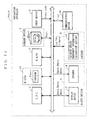
- FIG. 1 shows the hardware structure of a navigation apparatus Anavi1 according to a first embodiment of the present invention.
- the navigation apparatus Anavi1 is of a vehicle-mounting type, including a CPU 1, a ROM 2, a RAM 3, a storage device 4, an input device 5, an output section 6, a locator 9, and a communications device 10.
- the ROM 2 is a program memory on which a program Pnavi1 for the navigation apparatus Anavi1 has been previously recorded. After the navigation apparatus Anavi1 is turned on, the CPU 1 starts executing the program Pnavi1 in the ROM 2. During when the program Pnavi1 is executed, the CPU 1 uses the RAM 3 as a working area.
- the storage device 4 is typically composed of a DVD drive, a CD drive, a hard disk drive, or an IC memory, and stores a cartographic database DBcart .
- the cartographic database DBcart may be of a known type, and composed of a collection of cartographic data Dcart included in one or more files.
- the cartographic data Dcart generally includes display data which is displayed as a map on a display device 7, and road network data which represents road connections on the map.
- the map here is a written representation of the geographic features on a given scale together with graphic characters and map symbols on a plane. This map is different from a route diagram, which will be described later. Examples of the map are a bird's eye view, and a plane view, among others.
- the bird's eye view represents three dimensional geographic and graphic features on a plane viewed from the above.
- the plane view represents objects on the ground projected onto a plane. In the plane view, those objects appear as viewed from directly above.
- the road network data represents road connections by nodes and links, which correspond to intersections and roads, respectively. Since the road network data is known, no further description is given.
- the cartographic data Dcart has been previously provided with additional information Iaddi .
- the additional information Iaddi is a cost or information about intersection names.
- the information about intersection names defines main intersections on the road network by name, and is assigned to nodes representing those main intersections.
- the cost is a weight each assigned to links, indicating a time or a distance to be taken for the user's vehicle to pass through the corresponding road. The cost is used at the time of route search (step S205 of FIG. 2).
- the input device 5 is typically composed of a remote controller, a touch sensor, keys, buttons, or a mouse, all of which are user operable, or a microphone through which the user inputs voice.
- the input device 5 may be composed of two or more of a remote controller, a touch sensor, keys, buttons, a mouse, and a microphone, depending on the design specifications of the navigation apparatus Anavi1 .
- the output section 6 is typically composed of the display device 7 and a speaker 8, and various data generated by the CPU 1 is outputted therefrom to the user. The various data will be described later when appropriate.
- the locator 9 corresponds to a movement information generation section in claims, and is typically composed of a GPS receiver (Global Positioning System).
- the locator 9 detects the user's current position, and generates position information Icp which indicates the coordinates of the position. Thus generated position information Icp is transferred to the CPU 1.
- the communications device 10 is typically composed of a VICS (Vehicle Information and Communication System) receiver, and received thereby is traffic information Itraf from beacons located in the proximity of roads.
- the traffic information Itraf specifies, by coordinates, the locations where the traffic accidents or jams are occurring.
- the communications device 10 may include a mobile phone to provide the navigation apparatus Anavi1 with the function of connecting to the Internet.
- the navigation apparatus Anavi1 Described next is the operation of the navigation apparatus Anavi1 .
- the CPU 1 starts executing the program Pnavi1 recorded on the ROM 2.
- the first half of the procedure written in the program Pnavi1 is shown in FIG. 2, and the second half in FIG. 3.
- the CPU 1 receives from the locator 9 the position information Icp indicating where the user currently is (step S201).
- step S202 from the cartographic database DBcart into the RAM 3, the CPU 1 reads the cartographic data Dcart representing the map of a predetermined area ⁇ 1.
- the predetermined area ⁇ 1 covers the area around the user's current position indicated by the position information Icp .
- the CPU 1 then performs map matching by using the cartographic data Dcart on the RAM 3 and the position information Icp so as to generate display data Ddis , indicating the user's current position by a mark appropriately disposed on any corresponding road in the predetermined area ⁇ 1.
- the resultant display data Ddis is forwarded to the display device 7.
- the display device 7 applies a display process in accordance with the display data Ddis so as to display on its screen a map including the mark overlaid on the position where the user is (step S202).
- the CPU 1 determines whether or not to perform route search (step S203).
- the deciding factor is an instruction signal Sinst1 coming from the input device 5, and responding thereto, the CPU 1 starts route search.
- the input device 5 generates the instruction signal Sinst1 if the user operates a predetermined portion thereof assigned to start route search.
- step S203 If the CPU 1 has received no instruction signal Sinst1 , before step S203, the procedure returns to step S201.
- step S204 the CPU 1 determines now is the time to perform route search, and the procedure goes to step S204.
- the CPU 1 then derives the coordinates of starting point and destination for route search this time (step S204).
- the starting point is the user's departure point.
- the CPU 1 derives the coordinates of departure point and destination by decoding coordinates information Icdn generated and provided by the input device 5.
- the coordinates information Icdn is the one specifying, by coordinates, the departure point and the destination inputted by the user via the input device 5.
- step S204 the user may input only the destination through the input device 5.
- the input device 5 generates the coordinates information Icdn for specifying the inputted destination by coordinates.
- the CPU 1 receives the resultant coordinates information Icdn, from which the coordinates of the destination are to be derived.
- the CPU 1 also receives from the locator 9 the position information Icp , from which the coordinates of the user's current position are to be derived.
- derived coordinates of the user's current position are used as those of the departure point.
- the CPU 1 searches for several routes under any well known route search algorithm such as the Dijkstra's algorithm (step S205). At this time, the CPU 1 works as a route search section in claims.
- routes share the same starting point and destination, which are those derived in step S204.
- the routes differ in course on the way.
- Such routes include, for example, those taking the user to his/her destination in the shortest distance and the second-shortest distance, or in the shortest time and the second-shortest time.
- an expression "optimum route” denotes a route taking the user from the current position toward the destination in the shortest distance or time, while an expression “next-optimum route” in the second-shortest distance or time.
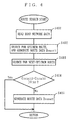
- step S205 The route search in step S205 is described in more detail with reference to the flowchart of FIG. 4.
- the CPU 1 first reads the cartographic data Dcart of a predetermined area ⁇ 2(step S401).
- the predetermined area ⁇ 2 typically is a rectangular region including both the starting point and the destination derived in step S204.
- the CPU 1 searches for one single optimum route by using the cartographic data Dcart on the RAM 3, more specifically, the road network data and the cost, i.e., additional information Iaddi .
- route data Droute11 which represents the found optimum route is generated on the RAM 3 (step S402).
- the route data Droute11 is typically composed of a node string configuring the optimum route.
- a total cost Ctotal11 of the optimum route is written onto the RAM 3.
- the total cost Ctotal11 is a value obtained by adding every cost previously assigned to all of the links configuring the optimum route.
- the CPU 1 searches for a next-optimum route (step S403).
- the cost for each of the links configuring the optimum route derived in step S402 is set larger this time, whereby a next-optimum route can be successfully derived in step S403 without coinciding with the optimum route.
- a total cost Ctotal12 of the next-optimum route is written onto the RAM 3.
- the total cost Ctotal12 is a value obtained by adding every cost assigned to all of the links configuring the next-optimum route.
- the CPU 1 determines whether or not the difference between the total costs Ctotal11 and Ctotal12 is exceeding a predetermined threshold value Vth1 (step S404).
- the threshold value Vth1 is determined according to the design specifications of the navigation apparatus Anavi1 , and is criteria by which to judge whether the next-optimum route is practical.
- the CPU 1 determines that no next-optimum route has been derived, and the procedure now goes to step S206 of FIG. 2. On the other hand, if not exceeding, the CPU 1 generates, on the RAM 3, route data Droute12 which represents the next-optimum route derived in step S403 (step S405).
- the route data Droute12 is typically composed of a node string configuring the next-optimum route.
- step S405 the procedure goes to step S206 of FIG. 2.
- the CPU 1 determines whether or not both the optimum and next-optimum routes are derived in step S205 (step S206). This determination is based on whether the RAM 3 carries the route data Droute11 only or together with the route data Droute12 .
- step S212 If determined in step S206 that only the optimum route has been derived, the procedure goes to step S212.
- the CPU 1 then generates message data Dmess1 , and transfers it to the output section 6.
- the message data Dmess1 is image data or sound data, with which the user is notified in the form of a message that derived in step S205 is only the optimum route.
- the output section 6 performs the display process in the display device 7, or a sound output process in the speaker 8 so as to output the message to the user (step S212).
- step S213 will be described later of FIG. 3, i.e., circled letter A .
- step S207 if determined in step S206 that both of the optimum and next-optimum routes have been derived, the procedure goes to step S207 for a process of generating and displaying warning data Dwarn (step S207). In the present embodiment, any one of the following first to fourth generation/display processes is performed in step S207.
- the first generation/display process is now described in detail by referring to the flowchart of FIG. 5.
- the procedure of FIG. 5 used as the basis of the warning data Dwarn is a displaying portion of the cartographic data Dcart read out in step S401.
- the CPU 1 receives from the locator 9 the position information Icp indicating where the user currently is (step S501). The CPU 1 then performs map matching by using both the position information Icp and the corresponding cartographic data Dcart so as to generate, on the RAM 3, intermediate image data Dim11 in which a mark denoting the user's current position is appropriately disposed on any corresponding road in the map (step S502).
- the CPU 1 On the basis of the coordinates information Icdn of the destination used in step S205 and the intermediate image data Dim11 generated in step S502, the CPU 1 then generates, on the RAM 3, intermediate image data Dim12 in which a mark denoting the destination is disposed on the map (step S503).
- the CPU 1 generates warning data Dwarn11 which allows the optimum and next-optimum routes to be displayed on the map (step S504). More specifically, such warning data Dwarn11 allows the display device 7 to display the user's current position, the destination, and the optimum and next-optimum routes overlaid all together on the map.
- step S504 it is preferable if the warning data Dwarn11 displays the optimum and next-optimum routes in different colors or line styles on the map. With such warning data Dwarn11 displayed in step S505, the user can distinguish the optimum and next-optimum routes easily which is which.
- step S504 it is still preferable if the optimum route is displayed in more noticeable color or line style than the next-optimum route. Accordingly, the optimum route looks conspicuous with the warning data Dwarn11 displayed, enabling the user to intuitively recognize it.
- steps S501 to S504 can be carried out in any desired order, but step S501 should be followed by step S502.
- step S504 the CPU 1 transfers the generated warning data Dwarn11 to the display device 7.
- the display device 7 performs the display process in accordance with the warning data Dwarn11 so as to display on its screen a map image having, at least, the optimum and next-optimum routes overlaid thereon.
- a map image is shown in FIG. 6A.
- the user sees several available route options, i.e., optimum and next-optimum routes (step S505).
- step S505 the procedure goes to step S208 of FIG. 2.
- FIG. 7 Compared with FIG. 5, the procedure of FIG. 7 further includes steps S701 to S704. This is the only difference therebetween, and in FIG. 7, any step identical to that in FIG. 5 is under the same step number and not described again.
- step S501 After the CPU 1 receives the position information Icp (step S501), the procedure goes to step S701.
- the optimum and next-optimum routes share the same starting point and the destination, but vary in course on the way.
- the optimum and next-optimum routes thus head in different directions at a certain intersection. In the below, such an intersection is referred to as a junction intersection.
- step S701 in comparison between the route data Droute11 and Droute12 in terms of node strings, the CPU 1 specifies, by coordinates, which node is the junction intersection. Based on the coordinates of the node, i.e., junction intersection, and the coordinates indicated by the position information Icp , the CPU 1 determines whether or not the user is being close to the junction intersection (step S701). More specifically, in step S701, those coordinates are used to calculate the distance between the user's current position and the junction intersection, and the calculated value is compared with a predetermined threshold value Vth2 .
- the threshold value Vth2 is determined in advance according to the design specifications of the navigation apparatus Anavi1 , and criteria by which to judge whether the user is approaching an intersection.
- step S701 if determined that the user is being close to no junction intersection, steps S502 to S505 are carried out, and as a result, the user sees an image based on the warning data Dwarn11 .
- step S702 if determined that the user is being close to the junction intersection in step S701, the procedure goes to step S702.
- the CPU 1 performs map matching by using the position information Icp and the corresponding cartographic data Dcart so as to generate, on the RAM 3, intermediate image data Dim21 in which a mark denoting the user's current position is correctly overlaid on any corresponding road in the map (step S702).
- the cartographic data Dcart in step S702 represents an enlarged map covering the area around the junction intersection. In this sense, steps S702 and S502 are not the same.
- the CPU 1 On the basis of the route data Droute11 and Droute12 derived in step S205, and the intermediate image data Dim21 generated in step S702, the CPU 1 generates warning data Dwarn12 in which roads around the junction intersection on the optimum and next-optimum routes are arranged on the map (step S703). More specifically, the warning data Dwarn12 is image data which allows the display device 7 to display an enlarged map of around the junction intersection including the starting point, and the optimum and next-optimum routes together.
- step S703 it is preferable if the optimum and next-optimum routes are displayed in different colors or line styles. It is still preferable if the optimum route is displayed in more noticeable color or line style than the next-optimum route. Moreover, steps S702 and S703 may be switched in order.
- step S703 the CPU 1 transfers the generated warning data Dwarn12 to the display device 7.
- the display device 7 performs the display process based on the warning data Dwarn12 so as to display on its screen such an image as shown in FIG. 6B.
- the image at least shows the optimum and next-optimum routes overlaid on the enlarged map of around the junction intersection. With such an image, the user can easily perceive the specific location where several routes (optimum and next-optimum routes) are branched (step S704). After the image is displayed, the procedure goes to step S208 of FIG. 2.
- the CPU 1 receives from the locator 9 the position information Icp indicating where the user currently is (step S801). Then, the CPU 1 generates intermediate image data Dim31 by using background image data Dbg1 and the received position information Icp (step S802).
- the background image data Dbg1 has been previously at hand, and represents the background of the image displayed in step S806.
- the intermediate image Dim31 shows the user's departure point, which is indicated by the position information Icp , by a mark overlaid on the background image of the background image data Dbg1 .
- the CPU 1 Based on the coordinates information Icdn of the destination used in step S205, and the intermediate image data Dim31 generated in step S802, the CPU 1 generates intermediate image data Dim32 having another mark overlaid on the background image to indicate the destination (step S803).
- the CPU 1 reads, from the cartographic database DBcart , the additional information Iaddi for whatever intersection names in need (step S804).
- read in step S804 are names of the main intersections found in the route data Droute11 and Droute12 , i.e., located on the optimum and next-optimum routes.
- the CPU 1 disposes the intersection names onto the background image, and then generates warning data Dwarn13 on the RAM 3 by connecting those intersection names by lines so that the optimum and next-optimum routes are represented thereby (step S805).
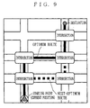
- the warning data Dwarn13 allows the display device 7 to display a route diagram, in which several major intersections located on several routes are connected by lines.
- step S805 similarly in step S503, the optimum route is preferably displayed in different color or line style from the next-optimum route. Further, the color or line style of the optimum route preferably looks conspicuous than that of the next-optimum route.
- steps S801 to S805 can be carried out in any desired order, but step S801 should be followed by step S802.
- step S805 the CPU 1 transfers the generated warning data Dwarn13 to the display device 7.
- the display device 7 performs the display process based on the received warning data Dwarn13 so as to display on its screen such a route diagram as shown in FIG. 9. With such a route diagram displayed, the user can perceive what route options are available, i.e., optimum and next-optimum routes (step S806).
- step S806 the procedure goes to step S208 of FIG. 2.
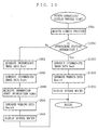
- FIG. 10 Described next is the fourth generation/display process by referring to FIG. 10.
- the procedure of FIG. 10 further includes steps S1001 to S1004. This is the only difference therebetween, and in FIG. 10, any step identical to that in FIG. 8 is under the same step number and not described again.
- the processes in steps S1001 to S1004 correspond to those of steps S701 to S704 which have been described in the second generation/display process, and thus are not described here in detail.
- step S1004 the procedure goes to step S208 of FIG. 2.
- the user selects one of those.
- the most striking feature is that the CPU 1 automatically performs route selection by monitoring the user's (i.e., the vehicle's) actual movement without the user having to operate the input device 5.
- the CPU 1 automatically performs route selection by monitoring the user's (i.e., the vehicle's) actual movement without the user having to operate the input device 5.
- an exemplary method for selecting one single route is described.
- the CPU 1 instructs the locator 9 to transfer the position information Icp , i.e., movement information Imove.
- the locator 9 generates the position information Icp indicating where the user currently is, and transfers it to the CPU 1.
- the locator 9 exemplarily works as the movement information generation section in claims.
- the CPU 1 then receives the position information Icp coming from the locator 9 (step S208). Alternatively, in the present embodiment, the CPU 1 may use the position information Icp received in step S207 as the movement information Imove.
- the CPU 1 then performs map matching by using the cartographic data Dcart on the RAM 3 and the received position information Icp so as to calculate the user's current position on the road network on the map (step S209). At this time, the CPU 1 works as a calculation section in claims.
- step S210 the CPU 1 determines on which of the optimum and next-optimum route the user currently is (step S210).
- map matching performed in step S209 is done to bring the user's current position to the corresponding road on the map.
- the calculation result of the map matching thus tells the CPU 1 on which route the user is now moving.
- the procedure returns to step S207 so that those several routes remain displayed for the user.
- step S210 if the user is determined as being on one specific route (i.e., optimum or next-optimum route), the route is accordingly selected (step S211). That is, the CPU 1 selects either the route data Droute11 or Droute12 . In step S211, the CPU 1 works as a selection section in claims. Then, the procedure goes to step S213 of FIG. 3, i.e., circled letter A .
- the user may be on none of the routes. If this is the case, with no relation to the present embodiment, no description is given here.
- step S211 or S212 the CPU 1 will be completed specifying one route so as to guide the user therealong, i.e., optimum or next-optimum route. More specifically, the CPU 1 guides the user's vehicle depending on which route data has been selected, i.e., based on Droute11 or Droute12 (step S213).
- FIG. 11 is a flowchart showing the detailed procedure in step S213.
- the CPU 1 receives from the locator 9 the position information Icp indicating where the user currently is (step S1101).
- step S1102 from the map database DBcart to the RAM 3, the CPU 1 reads out the cartographic data Dcart representing the map of a predetermined area ⁇ 3.
- the predetermined area ⁇ 3 typically covers the area around the user's current position indicated by the position information Icp .
- the CPU 1 uses the cartographic data Dcart on the RAM 3, and does not perform reading from the cartographic database DBcart .
- the CPU 1 generates image data.
- the image data allows the display device 7 to display the route from the user's current position toward the destination overlaid on any corresponding road on the map.
- the CPU 1 generates sound data instructing the user to make a left or right turn or go straight.
- the CPU 1 generates, on the RAM 3, the guidance data Dguid composed of image data only or together with sound data (step S1102). At this time, the CPU 1 works as a guidance data generation section in claims.
- the CPU 1 then transfers the guidance data Dguid to the output section 6.
- the output section 6 performs the display process in the display device 7, or the sound output process in the speaker 8 based on the guidance data Dguid .
- the display device 7 performs the display process based on the image data included in the guidance data Dguid so as to display on its screen such an image as shown in FIG. 12.
- the screen of the display device 7 displays the user's current position, the destination, and the route selected in step S211 overlaid all together on the map.
- the speaker 8 outputs sound to the user based on the sound data in the guidance data Dguid (step S1103). Thereby, the CPU 1 guides the user toward the destination.
- step S1103 After step S1103 is through, the procedure goes to step S214. Then, the CPU 1 compares the user's current position and the destination derived in step S204 in terms of coordinates so as to determine whether or not the user has reached the destination (step S214).
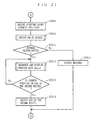
- step S215 the procedure determines whether a predetermined condition is satisfied for starting re-routing (step S215).
- the deciding factor in step S215 is an instruction signal Sinst2 coming from the input device 5, and responding thereto, the CPU 1 starts re-routing.
- the input device 5 generates the instruction signal Sinst2 if the user operates a predetermined portion thereof assigned to start re-routing.
- step S215 If the instruction signal Sinst2 has not been received before step S215, the procedure returns to step S213 so that the user is guided continuously along the currently-found route.
- the CPU 1 determines that now is the time to start re-routing, and the procedure goes to step S216.
- the CPU 1 then derives the coordinates of the starting point for re-routing this time (step S216). More specifically, in step S216, the CPU 1 receives the position information Icp from the locator 9 so that the user's current position can be specified by coordinates. The user's current position thus derived is now used as the starting point for re-routing. Note that, in re-routing, the coordinates of the destination remain the same as those used in step S204.
- step S216 When step S216 is through, the procedure returns to step S205 for re-routing.
- the processes thereafter are understood from the above, and not described here again. It should be noted that a starting point is a departure point in the above, but in re-routing, a starting point is the user's current position.
- the cost for each of the links configuring any already-found route is set larger this time, whereby any new route can be successfully derived without coinciding with the route found so far.
- step S207 displayed are several route options starting from the starting point, i.e., the current position (see FIGS. 6A and 9).
- the navigation apparatus Anavi1 automatically selects one route from several others derived through route search on the basis of the user's movement, i.e., movement information Imove (position information Icp ).
- the navigation apparatus Anavi1 guides the user along the selected route. With such function, the navigation apparatus Anavi1 does not require the user cumbersome operation for route selection.
- the display device 7 applies the display process according to the warning data Dwarn11 to Dwarn13 so as to offer optimum and next-optimum routes to the user.
- the CPU 1 may generate warning data Dwarn1v , and transfer it to the speaker 8 to have the speaker 8 performed the audio output process in accordance therewith so as to provide the user with optimum and next-optimum routes by sound.
- the warning data Dwarn1 may be outputted from the output section 6 in the form of image or sound.
- the route data Droute1 is presumably composed of a node string, but may be of a link string.
- the deciding factor for starting re-routing is whether or not an instruction signal Sinst2 has been received before step S215.
- the deciding factor may be any other condition set for the purpose.
- the CPU 1 may start re-routing when the user's current position comes closer to an intersection, or when any traffic accident or jam is occurring on a route along which the user is guided in step S213.
- the traffic information Itraf received by the communications device 10 is utilized.
- routes are plurally found from the starting point (departure point or the user's current position) to one destination in step S205.
- the destination is not necessarily only one, and route options searched from the starting point (departure point or the user's current position) to several destinations may be displayed in step S207.
- FIG. 14 shows the structure of the navigation apparatus Anavi2 .
- the navigation apparatus Anavi2 of FIG. 14 includes a ROM 12 as an alternative to the ROM 2, and the locator 9 further includes an azimuth sensor 13 in addition to the receiver in the first embodiment.
- the ROM 12 is a program memory on which a program Pnavi2 for the navigation apparatus Anavi2 has been previously recorded.
- the azimuth sensor 13 is also called a gyro sensor.
- the azimuth sensor 13 detects in which direction the user's vehicle is now heading, and generates direction information Idrc which indicates the detected direction. Thus generated direction information Idrc is transferred to the CPU 1.
- the CPU starts executing the program Pnavi2 recorded on the ROM 12.
- FIG. 15 is a flowchart showing the first half of the procedure of the CPU 1 written in the program Pnavi2 .
- the second half of the procedure in the program Pnavi2 shows no difference from that in FIG. 3, and thus is not described nor shown again.
- FIG. 15 includes steps S1501 to 51503 in place of steps S208 to S210. This is the only difference therebetween, and in FIG. 15, any step identical to that in FIG. 2 is provided with the same step number and is not described again.
- the CPU 1 With several route options displayed to the user after step S207 in FIG. 15, the CPU 1 generates angle information Iang1 for the optimum route, and angle information Iang2 for the next-optimum route (step S1501).
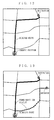
- FIG. 16 is a diagram for illustrating the angle information Iang1 and Iang2.
- the program Pnavi2 previously defines a reference line Lref (see two-dotted line), which is a line started from a junction intersection (see first embodiment) towards a predetermined direction.
- the CPU 1 calculates an angle ⁇ 1 between the reference line Lref and the optimum route at the junction intersection, and retains the calculation result on the RAM 3 as the angle information Iang1 .
- the CPU 1 also calculates an angle ⁇ 2 between the reference line Lref and the next-optimum route at the junction intersection, and retains the calculation result on the RAM 3 as the angle information Iang2 .
- step S1501 the CPU 1 instructs the azimuth sensor 13 to transfer the direction information Idrc as another example of the movement information Imove.
- the azimuth sensor 13 generates the direction information Idrc indicating in which direction the user is now heading, and transfers it to the CPU 1.
- the direction information Idrc specifies the angle at which the user is heading with reference to the reference line Lref.
- the azimuth sensor 13 exemplarily works as the movement information generation section in claims.
- the CPU 1 receives such direction information Idrc from the azimuth sensor 13 as the movement information Imove (step S1502).
- the CPU 1 determines whether the direction in which the user's vehicle is now heading is practically the same as that of the optimum route or the next-optimum route (step S1503). More specifically, the CPU 1 compares the direction information Idrc received in step S1502 with the angle information Iang1 and Iang2 on the RAM 3 so as to determine whether the value of the direction information Idrc coincides with only either of the angle information Iang1 or Iang2.
- the CPU 1 determines that the user is not positioned on only one route, and the procedure returns to step S207 to continually display several routes to the user.
- step S1503 in the case that the value of the direction information Idrc coincides with one of the angle information Iang1 and Iang2 , the CPU 1 determines that the user is now on only one route, i.e., optimum or next-optimum route, and accordingly selects the route (step S211).
- step S211 After step S211 is through, the procedure goes to step S213 of FIG. 3, i.e., circled letter A , and goes through the same process as described in the first embodiment.
- the navigation apparatus Anavi2 automatically selects one route from several others derived through route search on the basis of the user's movement, i.e., movement information Imove (direction information Idrc ). Therefore, the navigation apparatus Anavi2 does not require the user cumbersome operation for route selection.
- the CPU 1 has no need to obtain the direction information Idrc until the user reaches a junction intersection. Therefore, another step may be provided between steps S1501 and S1502 to determine whether the user has reached any junction intersection. The procedure may return to step S207 if not yet reached, and if reached, go to step S1502.
- FIG. 17 is a diagram showing the structure of the navigation apparatus Anavi3 .
- the navigation apparatus Anavi3 includes a ROM 14 as an alternative to the ROM 2. This is the only difference, and in FIG. 17, any constituent identical to that in FIG. 1 is under the same reference numeral, and no further description is given.
- the ROM 14 is a program memory on which a program Pnavi3 for the navigation apparatus Anavi3 has been previously recorded.
- the CPU 1 starts executing the program Pnavi3 recorded on the ROM 14.
- FIG. 18 is a flowchart showing the first half of the procedure of the CPU 1 written in the program Pnavi3 .
- the second half of the procedure in the program Pnavi3 shows no difference from that in FIG. 3, and thus is not described nor shown again.
- FIG. 18 includes steps S1801 to S1803 in place of steps S209 to S211. This is the only difference therebetween, and in FIG. 18, any step identical to that in FIG. 2 is provided with the same step number and is not described again.
- step S207 the CPU 1 receives the position information Icp from the locator 9 (step S1801). Then, the CPU 1 generates trail information Itraj as another example of the movement information Imove (step S1802). At this time, the CPU 1 works as a trail information generation section in claims. More specifically, every time in step S1802, the trail information Itraj is to be updated by being added with coordinate values of the position information Icp derived in step S1801. Thus, the trail information Itraj indicates the trail the user has moved so far, and is composed of the string of coordinate values indicated by several pieces of position information Icp .
- the CPU 1 determines whether or not the user's trail substantially coincides with only one route, i.e., optimum or next-optimum route (step S1803). To be more specific, in comparison among the trail information Itraj generated in step S1802, and the route data Droute11 and Droute12 on the RAM 3, the CPU 1 determines if the route specified by the trail information Itraj coincides with only either of the optimum route specified by the route data Droute11 or the next-optimum route specified by the route data Droute12 .
- step S1802 the CPU 1 determines that the user is not being on one route so that the procedure returns to step S207 to continually display several routes for the user.
- step S1802 the CPU 1 determines that the user is now being on one route, and accordingly selects the route on which the user currently is (step S211).
- step S211 After step S211 is thorough, the procedure goes to step S213 of FIG. 3, i.e., circled letter A , and goes through the process in the same manner as the first embodiment.
- the navigation apparatus Anavi3 automatically selects one route from several others derived through route search on the basis of the user's movement, i.e., movement information Imove (trail information Itraj ). Therefore, the navigation apparatus Anavi3 does not require the user cumbersome operation for route selection.
- the navigation apparatuses Anavi1 to Anavi3 are presumably of a vehicle-mounting type. This is not restrictive, and the navigation apparatuses Anavi1 to Anavi3 are easily realized in the portable application. Moreover, the programs Pnavi1 to Pnavi3 can be easily implemented in computer devices such as mobile phones, Personal Digital Assistants (PDAs), and personal computers, and accordingly those computer devices can be easily provided with the navigation function.
- PDAs Personal Digital Assistants
- the programs Pnavi1 to Pnavi3 may be distributed in recording media typified by CDs, DVDs (Digital Versatile Disks), MO (Magnetic-Optical) disks, or semiconductor memories. Also, the programs Pnavi1 to Pnavi3 may be stored on the storage device of a network server so that the computer devices can download those programs therefrom.
- FIG. 19 is a diagram showing the hardware structure of navigation apparatuses Anavi4 to Anavi6 according to fourth to sixth embodiments, respectively, of the present invention.
- the navigation apparatus Anavi when simply referred to as “navigation apparatus Anavi ", it means all of the navigation apparatuses Anavi4 to Anavi6 .
- the navigation apparatus Anavi is of a vehicle-mounting type, and includes a CPU 21, a ROM 22, a RAM 23, a storage device 24, an input device 25, an output section 26, a locator 29, and a communications device 210.
- the ROM 22 is a program memory on which programs Pnavi4 to Pnavi6 for the navigation apparatuses Anavi4 to Anavi6 , respectively, have been previously recorded. After the navigation apparatuses Anavi4 to Anavi6 are turned on, the CPU 21 starts executing the programs Pnavi4 to Pnavi6 in the ROM 22. During when the programs Pnavi4 to Pnavi6 are executed, the CPU 21 uses the RAM 23 as a working area.
- the storage device 24 stores the cartographic database DBcart as does the storage device 4 in the first to third embodiments.
- the cartographic database DBcart may be of a known type, and composed of a collection of cartographic data Dcart included in one or more files.
- the cartographic data Dcart generally includes display data which is displayed as a map on a display device 27, and road network data which represents road connections on the map.
- the map is the same as that in the first to third embodiments, and is not the same as the route diagram which will be described later.
- the road network data and the cartographic data Dcart are the same as those in the fist to third embodiments, and no further description is given here.
- the cartographic data Dcart includes the costs, i.e., the additional information Iaddi , are used at the time of route search (step S2005 in FIG. 20, and step S2010 in FIG. 21).
- the input device 25 is the same as the input device 5 in the first to third embodiments, and thus is not described again.
- the output section 26 is typically composed of the display device 27 and a speaker 28.
- the locator 29 generates position information Icp which specifies the user's current position by coordinates. The position information Icp is then transferred to the CPU 21.
- the communications device 210 is in the same structure as the communications device 10 in the first to third embodiments, and no further description is given.
- FIGS. 20 and 21 are flowcharts showing the procedure of the CPU 21 written in the program Pnavi4.
- the CPU 21 receives from the locator 29 the position information Icp indicating where the user currently is as in step S201 of FIG. 2 (step S2001).
- the CPU 21 operates similarly to step S202 of FIG. 2 so that the display device 27 displays a map including a mark overlaid on the position where the user is (see first embodiment)(step S2002).
- the CPU 21 determines whether or not to perform route search in the similar manner to step S203 of FIG. 2 (step S2003), and if no instruction signal Sinst1 has been received, the procedure returns to step S2001.
- step S2003 the CPU 1 determines that now is the time to perform route search for the first time (first route search), and the procedure goes to step S2004.
- the CPU 21 then derives both coordinates of a departure point and a destination for the first route search (step S2004).
- step S2004 the CPU 21 derives the coordinates of departure point and destination by decoding coordinates information Icdn generated and provided by the input device 25.
- the coordinates information Icdn is the one specifying, by coordinates, the departure point and the destination inputted by the user via the input device 25.
- step S2004 the user may input only the destination through the input device 25.
- the input device 25 generates the coordinates information Icdn for specifying the inputted destination by coordinates.
- the CPU 21 receives the resultant coordinates information Icdn, from which the coordinates of the destination are to be derived.
- the CPU 21 also receives from the locator 29 the position information Icp , from which the coordinates of the user's current position are to be derived.
- derived coordinates of the user's current position is used as those of the departure point.
- step S2005 the CPU 21 then performs the first route search under any well known route search algorithm, for example, Dijkstra's algorithm to find a first optimum route (step S2005).
- the process in step S2005 is the same as that in step S205 of FIG. 2, and is not described here.
- the "first optimum route” denotes a route taking the user from the current position toward the destination in the shortest distance or time, that is, the route with which the total cost Ctotal1 from the departure point toward the destination is minimum.
- the CPU 21 After route search, the CPU 21 generates, on the RAM 23, route data Droute1 which indicates the first optimum route.
- the route data Droute1 is generally composed of a node string configuring the first optimum route.
- the total cost Ctotal1 is written onto a predetermined region of the RAM 23 as required.
- the total cost Ctotal1 is a value obtained by adding every cost assigned to all of the links configuring the first optimum route.
- step S2006 the CPU 21 guides the user's vehicle along the first optimum route derived in step S2005.
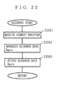
- FIG. 22 is a flowchart showing the specific procedure in step S2006.
- the CPU 21 goes through the same process as in step S1101 of FIG. 11 so as to receive the position information Icp indicating the user's current position from the locator 29 (step S2201).
- the CPU 21 generates guidance data Dguid on the RAM 23 (step S2202), and transfers it to the output section 26.
- the output section 26 accordingly performs the display process in the display device 27, or the sound output process in the speaker 28 based on the guidance data Dguid .
- the display device 27 performs the display process based on the image data included in the guidance data Dguid so as to display on its screen such an image as shown in FIG. 23A.
- the screen of the display device 27 displays the user's current position, the destination, and the first optimum route overlaid together on the map.
- the speaker 28 outputs sound to the user based on the sound data in the guidance data Dguid (step S2203). Thereby, the CPU 21 guides the user toward the destination.
- step S2203 After step S2203 is through, the procedure goes to step S2007. Then, the CPU 21 compares the user's current position and the destination in terms of coordinates so as to determine whether or not the user has reached the destination (step S2007).
- step S2008 determines whether a predetermined condition is satisfied for starting route search for the second time (second route search)(step S2008).
- the deciding factor in step S2008 is an instruction signal Sinst2 coming from the input device 25, and responding thereto, the CPU 21 starts the second route search.
- the input device 25 generates the instruction signal Sinst2 if the user operates a predetermined portion thereof assigned to start the second route search.
- step S2008 If no instruction signal Sinst2 has been received before step S2008, the procedure returns to step S2006 so that the user is guided continuously along the first optimum route.
- the CPU 21 determines that now is the time to start the second route search, and the procedure goes to step S2009 of FIG. 21.
- the CPU 21 then derives the coordinates of the departure point (the user's current position) for the second route search (step S2009). More specifically, the CPU 21 receives the position information Icp from the locator 29 so that the user's current position can be specified by coordinates.
- the user's current position thus derived is used as the departure point for the second route search. Note that, in the second route search, the coordinates of the destination remain the same as those used in step S2004.
- the CPU 21 then performs the second route search to find several of second routes under the route search algorithm (step S2010).
- the second routes should vary in course on the way but share the same departure point and destination, which are those derived in step S2009.
- the second routes should not coincide with the first optimum route.
- Such second routes include, for example, those taking the user to his/her destination in the shortest distance and the next-shortest distance, and in the shortest time and the next-shortest time.
- an expression "second optimum route” denotes a route taking the user from the current position toward the destination in the shortest distance or time, while an expression “second next-optimum route” in the next-shortest distance or time.
- the second route search is described in more detail with reference to the flowchart of FIG. 24.
- the CPU 21 first reads the road network data representing the road network of a predetermined area ⁇ 4(step S2401).
- the predetermined area ⁇ 4 typically is a rectangular region including both the user's current point and the destination derived in step S2009.
- the CPU 21 searches for one single second optimum route by using the road network data on the RAM 23 and the costs, i.e., additional information Iaddi , so as to generate, on the RAM 23, second route data Droute21 which represents the found second optimum route (step S2402).
- the second route data Droute21 is typically composed of a node string configuring the second optimum route.
- a total cost Ctotal21 of the second optimum route is written onto the RAM 23.
- the total cost Ctotal21 is a value obtained by adding every cost assigned to all of the links configuring the second optimum route.
- step S2402 it should be noted that the user is now guided along the first optimum route, that means, the user is now on the first optimum route. Accordingly, the route considered currently optimum from the user's current position toward the destination is the first optimum route, but in step S2402, there needs to find a second optimum route being different from the first optimum route.
- the cost for each of the links configuring the first optimum route derived in step S2005 is set larger this time, whereby a second optimum route can be successfully derived in step S2402 without coinciding with the first optimum route.
- the CPU 21 uses the road network data on the RAM 23 and the costs, i.e., additional information Iaddi , so as to search for the second next-optimum route (step S2403).
- the second next-optimum route needs not to coincide with the first and second optimum routes
- the cost for each of the links configuring the second optimum route derived in step S2402 is set larger this time, whereby any new route can be successfully derived in step S2403 without coinciding with the first and second optimum routes.
- a total cost Ctotal22 of the second next-optimum route is written onto the RAM 23.
- the total cost Ctotal22 is a value obtained by adding every cost assigned to all of the links configuring the second next-optimum route.
- the CPU 21 determines whether or not the difference between the total costs Ctotal21 and Ctotal22 is exceeding a predetermined threshold value Vth1 (step S2404).
- the threshold value Vth1 is determined according to the design specifications of the navigation apparatus Anavi4, and is criteria by which to judge whether the second next-optimum route is practical.
- the CPU 21 determines that no second next-optimum route has been derived, and the procedure now goes to step S2011 of FIG. 21. On the other hand, if not exceeding, the CPU 21 generates, on the RAM 23, route data Droute22 which represents the second next-optimum route derived in step S2403 (step S2405).
- the second route data Droute22 is typically composed of a node string configuring the second next-optimum route.
- step S2405 the procedure goes to step S2011 of FIG. 21 so that the CPU 21 determines whether or not the second route is plurally derived in step S2010 (step S2011). This determination is based on whether the RAM 23 carries the second route data Droute21 only or together with the second route data Droute22.
- step S2011 If determined in step S2011 that only the second optimum route has been derived, the procedure goes to step S2015.
- the CPU 21 then generates warning data Dwarn1 , and transfers it to the output section 26.
- the warning data Dwarn1 is image data or sound data, with which the user is notified in the form of a message that derived in step S2010 is only one single second route.
- the output section 26 performs the display process in the display device 27, or the sound output process in the speaker 28 so as to output the message to the user (step S2015).
- step S2015 After step S2015 is through, the procedure goes to step S2006 of FIG. 20, i.e., circled letter B .
- the CPU 21 guides the user (step S2006 of FIG. 20).
- step S2006 is the same as above, and thus not described again. It should be noted, however, used as the basis in this step S2006 is not the first optimum route derived in step S2005 but the second optimum route derived in step S2010.
- step S2011 if determined in step S2011 that several of the second routes have been derived, the procedure goes to step S2012 for a process of generating and displaying warning data Dwarn2 (step S2011). In the present embodiment, any one of the following first to fourth generation/display processes is performed in step S2011.
- the first generation/display process is now described in more detail by referring to the flowchart of FIG. 25.
- the procedure of FIG. 25, used as the basis of the warning data Dwarn21 is a displaying portion of the cartographic data Dcart read out in step S2401.
- the CPU 21 receives from the locator 29 the position information Icp indicating where the user currently is (step S2501). The CPU 21 then performs map matching by using both the position information Icp and the corresponding cartographic data Dcart so as to generate, on the RAM 23, intermediate image data Dim11 in which a mark denoting the user's current position is appropriately disposed on any corresponding road in the map (step S2502).
- the CPU 21 On the basis of the coordinates information Icdn about the destination used in step S2010 and the intermediate image data Dim11 generated in step S2502, the CPU 21 generates, on the RAM 23, intermediate image data Dim12 in which a mark denoting the destination is disposed on the map (step S2503).
- the CPU 21 generates warning data Dwarn21 which enables the second optimum and second next-optimum routes to be displayed on the map (step S2504).
- warning data Dwarn21 allows the display device 27 to display the user's current position, the destination, and the second optimum and second next-optimum routes overlaid together on the map.
- step S2504 it is preferable if the warning data Dwarn21 displays the second optimum and second next-optimum routes in different colors or line styles on the map. With such warning data Dwarn21 displayed in step S2505, the user can distinguish the second optimum and second next-optimum routes easily which is which.
- step S2504 it is still preferable if the second optimum route is displayed in more noticeable color or line style than the second next-optimum route. Accordingly, the second optimum route looks conspicuous with the warning data Dwarn21 displayed, enabling the user to intuitively recognize it.
- steps S2501 to S2504 can be carried out in any desired order, but step S2501 should be followed by step S2502.
- step S2504 the CPU 21 transfers the generated warning data Dwarn21 to the display device 27.
- the display device 27 performs the display process in accordance with the warning data Dwarn21 so as to display on its screen a map image having, at least, the second optimum and second next-optimum routes overlaid thereon.
- a map image is shown in FIG. 23B.
- the user sees several available second routes, i.e., second optimum and second next-optimum routes (step S2505).
- step S2505 the procedure goes to step S2013.
- FIG. 26 Described next is the second generation/display process by referring to FIG. 26.
- the procedure of FIG. 26 further includes steps S2601 to S2604. This is the only difference therebetween, and in FIG. 26, any step identical to that in FIG. 25 is under the same step number and not described again.
- step S2501 After the CPU 21 receives the position information Icp (step S2501), the procedure goes to step S2601.
- the second optimum and second next-optimum routes share the same departure point and the destination, but vary in course on the way.
- the second optimum and second next-optimum routes thus head in different directions at a certain intersection. In the below, such an intersection is referred to as a junction intersection.
- step S2501 the CPU 21 specifies, by coordinates, which node is the junction intersection (step S2601). Based on the coordinates of the node, i.e., junction intersection, and the coordinates indicated by the position information Icp , the CPU 21 determines whether or not the user is being close to the junction intersection (step S2601). More specifically, in step S2601, those coordinates are used to calculate the distance between the user's current position and the junction intersection, and the calculated value is compared with a predetermined threshold value Vth2 .
- the threshold value Vth2 is determined in advance according to the design specifications of the navigation apparatus Anavi4 , and criteria by which to judge whether the user is approaching an intersection.
- step S2601 if determined that the user is approaching no junction intersection, steps S2502 to S2505 are carried out, and as a result, the user sees an image based on the warning data Dwarn21 .
- step S2601 if determined that the user is approaching a junction intersection in step S2601, the procedure goes to step S2602.
- the CPU 21 then performs map matching by using the position information Icp and the corresponding cartographic data Dcart so as to generate, on the RAM 23, intermediate image data Dim21 in which a mark denoting the user's current position is appropriately overlaid on any corresponding road in the map (step S2602).
- the cartographic data Dcart used in step S2602 represents an enlarged map covering the area around the junction intersection. In this sense, steps S2602 and S2502 are not the same.
- the CPU 21 generates warning data Dwarn22 in which roads around the junction intersection on the second optimum and second next-optimum routes are arranged on the map (step S2603). More specifically, the warning data Dwarn22 is image data which allows the display device 27 to display the user's current position, and the second optimum and second next-optimum routes overlaid all together on an enlarged map of around the junction intersection.
- step S2603 it is preferable if the second optimum and second next-optimum routes are displayed in different colors or line styles. It is still preferable if the second optimum route is displayed in more noticeable color or line style than the second next-optimum route. Moreover, steps S2603 and S2604 may be switched in order.
- step S2603 the CPU 21 transfers the generated warning data Dwarn22 to the display device 27.
- the display device 27 performs the display process based on the warning data Dwarn22 so as to display on its screen such an image as shown in FIG. 27A.
- the image shows at least the second optimum and second next-optimum routes overlaid on the enlarged map of around the junction intersection. With such an image, the user can easily perceive the specific location where several routes, i.e., second optimum and second next-optimum routes, are branched (step S2604). After the image is displayed, the procedure goes to step S2013.
- the CPU 21 receives from the locator 29 the position information Icp indicating where the user currently is (step S2801). Then, the CPU 21 generates intermediate image data Dim31 by using background image data Dbg1 and the received position information Icp (step S2802).
- the background image data Dbg1 has been previously at hand, and represents the background of the image displayed in step S2806.
- the intermediate image Dim31 shows the user's current position, which is indicated by the position information Icp , by a mark overlaid on the background image of the background image data Dbg1 .
- the CPU 21 Based on the coordinates information Icdn about the destination used in step S2010, and the intermediate image data Dim31 generated in step S2802, the CPU 21 generates intermediate image data Dim32 having another mark overlaid on the background image to indicate the destination (step S2803).
- the CPU 21 reads, from the cartographic database DBcart , the additional information Iaddi for whatever intersection names in need (step S2804).
- read in step S2804 are names of the main intersections found in the second route data Droute21 and Droute22, i.e., located on the second optimum and second next-optimum routes.
- the CPU 21 disposes the intersection names onto the background image, and then generates warning data Dwarn23 on the RAM 23 by connecting those names by lines so that the second optimum and second next-optimum routes are represented thereby (step S2805).
- the warning data Dwarn23 allows the display device 27 to display a route diagram, in which several major intersections located on several second routes are connected by lines.
- step S2805 similarly in step S2503, the second optimum route is preferably displayed in different color or line style from the second next-optimum route. Further, the color or line style of the second optimum route preferably looks conspicuous than that of the second next-optimum route.
- steps S2801 to S2805 can be carried out in any desired order, but step S2801 should be followed by step S2802.
- step S2805 the CPU 21 transfers the generated warning data Dwarn23 to the display device 27.
- the display device 27 performs the display process based on the received warning data Dwarn23 so as to display on its screen such a route diagram as shown in FIG. 27B. With such a route diagram displayed, the user can perceive what second route(s) are available, i.e., second optimum and second next-optimum routes (step S2806).
- step S2806 is through, the procedure goes to step S2013 of FIG. 21.
- FIG. 29 Described next is the fourth generation/display process by referring to FIG. 29.
- the procedure of FIG. 29 further includes steps S2601 to S2604. This is the only difference therebetween, and in FIG. 29, any step identical to that in FIG. 28 is under the same step number and not described again. Also, steps S2601 to S2604 are already described in the second generation/display process, and thus not described in detail here.
- step S2604 the procedure goes to step S2013 of FIG. 21.
- step S2012 By the time when step S2012 has been through, several of second routes will be available for the user to select one from those.
- the CPU 21 can automatically perform route selection by monitoring the user's (i.e., the vehicle's) actual movement without the user having to operate the input device 25.
- route selection by monitoring the user's (i.e., the vehicle's) actual movement without the user having to operate the input device 25.
- the CPU 21 determines whether or not the user's vehicle is now positioning on any one of the second routes (step S2013).
- the CPU 21 performs map matching by using the cartographic data Dcart on the RAM 23 and the position information Icp received from the locator 29.
- map matching is done to bring the user's current position to the corresponding road on the map.
- the result of map matching tells the CPU 21 on which of the second optimum and second next-optimum routes the user is now moving.
- step S2012 If the CPU 21 determines that the user is positioning on both of the second optimum and second next-optimum routes, the procedure returns to step S2012 so that several of the second routes are continually displayed to the user.
- step S2014 determines that the user is positioning on one of the second routes, i.e., second optimum or next-optimum route.
- the route is accordingly selected (step S2014). Then, the procedure goes to step S2006 of FIG. 20, i.e., circled letter B .
- the user may be on none of the second routes. If this is the case, with no relation to the present embodiment, no description is given here.
- step S2014 the CPU 21 guides the user (step S2006 of FIG. 20).
- the process in step S2006 is the same as above, and thus not described again. It should be noted, however, used as the basis in this step S2006 is not the first optimum route derived in step S2005 but either the second optimum route or the second next-optimum route selected in step S2014.
- the navigation apparatus Anavi4 can start searching for second routes if any predetermined starting condition is satisfied (step S2008) during when the apparatus is guiding the user along the first optimum route. Accordingly, with the navigation apparatus Anavi4 , the user has no more need to go off the first optimum route to know what other route options, i.e., second routes, are available. Further, since the second route is plurally found in step S2010, a wider range of route choices can be offered to the user to select therefrom whatever detour route meeting his/her preferences or actual traffic conditions.
- the display device 27 applies the display process according to the warning data Dwarn21 to Dwarn23 so that second optimum and second next-optimum routes are offered to the user.
- the CPU 21 may generate warning data Dwarn2v , and transfer it to the speaker 28 to have the speaker 28 performed the audio output process in accordance therewith so as to provide the user with second optimum and second next-optimum routes by sound.
- the warning data Dwarn2 may be outputted from the output section 26 in the form of image or sound.
- the warning data Dwarn21 to Dwarn23 are image data enabling at least the second optimum and second next-optimum routes to be displayed.
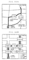
- the CPU 21 may generate warning data Dwarn21' to Dwarn26' which allow such images as shown in FIGS. 30 and 31 to be displayed.
- the additional information Iaddi needed for generating the warning data Dwarn21' to Dwarn26' is prepared in advance, and together with the information about intersection names and the costs, expected to include attribute information about roads represented by links.
- the attribute information is exemplary of road type information, road name information.
- the roads may be represented as Route X, Expressway Y, for example.
- the additional information Iaddi is also expected to include toll information used to calculate toll for toll roads.
- the warning data Dwarn21' is image data which allows the display device 27 to display on the map the time required for the user to reach the destination if he/she takes the second optimum route or the second next-optimum route.
- image elements for indicating such a time can be generated from the total cost Ctotal21 or Ctotal22 .
- the time may be displayed on the route diagram or the enlarged map.
- the warning data Drawn22 ' is image data which allows the display device 27 to display on the route diagram the distance to be covered by the user if he/she takes the second optimum route or the second next-optimum route.
- image elements for indicating such a distance can be generated from the total cost Ctotal21 or Ctotal22 .
- the distance may be displayed on the map or the enlarged map.
- the warning data Drawn23' is image data which allows the display device 27 to display on the enlarged map the toll for the user if he/she takes the second optimum route or the second next-optimum route.
- image elements for indicating such a toll can be generated from toll fee information which is a part of the additional information Iaddi .
- the toll may be displayed on the map or the route diagram.
- the warning data Drawn24' is image data which allows the display device 27 to display on the map the road attributes of the second optimum route or the second next-optimum route whichever the user takes.
- the road attributes include road type, road name, road number, or the like. Image elements for indicating such road attributes can be generated from attribute information which is a part of the additional information Iaddi .
- warning data Dwarn25' and Dwarn26' may be generated to display the attributes of the second and the second next-optimum routes on the route diagram and the enlarged map.
- searched and found by the CPU 21 are two routes, i.e., second optimum and second next-optimum routes. This is not restrictive, and three or more of second routes will do.
- the route data Droute is presumably composed of a node string, but may be of a link string.
- the deciding factor for starting second route search is whether or not an instruction signal Sinst2 has been received before step S2008. This is not restrictive, and the deciding factor may be second and third conditions set for the purpose in the following fifth and sixth embodiments.
- a navigation apparatus Anavi5 Described next is a navigation apparatus Anavi5 according to a fifth embodiment of the present invention.
- the basic hardware structure of the navigation apparatus Anavi5 is the same as that of the navigation apparatus Anavi4 , and thus FIG. 19 is referred to.
- the setting flag Fset is binary information which is criteria by which to judge whether second route search is to be performed. In the present embodiment, when the setting flag Fset indicates "1", it means that the second route search is to be preformed, but not with "0" indicated by the setting flag Fset .
- FIG. 32 is a flowchart showing the first half of the procedure of the CPU 21 of the navigation apparatus Anavi5 .
- the second half of the procedure shows no difference from that in FIG. 21, and thus is not described.
- FIG. 32 newly includes step S3201, and steps S3202 and S3203 in place of step S2008. These are the only differences therebetween, and in FIG. 32, any step identical to that in FIG. 20 is provided with the same step number and is not described again.
- FIG. 32 immediately after the navigation apparatus Anavi5 is turned on, the CPU 21 applies a process of writing a setting flag Fset (step S3201).
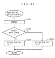
- FIG. 33 is a flowchart showing the detail process of step S3201.
- the CPU 21 first generates message data Dmess1 , and transfers it to the output section 26.
- the message data Dmess1 is image data or sound data, with which the user is asked a question whether or not to perform the second route search during when he/she is driving.
- the output section 26 goes through the display process or the sound output process. More specifically, the display device 27 displays on its screen such an image as shown in FIG. 34A based on message data Dmess2 which is image data. Also, the speaker 28 outputs such a sound as shown in FIG. 34B to the user based on the message data Dmess1 which is sound data. In this manner, the CPU 21 asks the user a question whether or not to perform the second route search (step S3301).
- the user makes an input via the input device 25.
- the user may manually operate the input device 25 via keys and mouse provided thereon, or speak into the microphone provided to the input device 25.
- the input device 25 generates response information Irep to designate yes or no about performing second route search, and transfers it to the CPU 21.
- the CPU 21 then decodes the received response information Irep so as to determine whether or not to perform the second route search (step S3302). If determined yes, the CPU 21 writes a value "1" as the setting flag Fset into the reserved region of the RAM 23 (step S3303). On the other hand, if determined no, writing into the reserved region of the RAM 23 is a value "0" (step S3304).
- step S3303 or S3304 After step S3303 or S3304 is through, the procedure goes to step S2001.
- the reason to perform step S3201 immediately after the navigation apparatus Anavi5 is turned on is for safety. It is the time when the user does not yet start his/her vehicle, and thus there considered no harm if the user operates the input device 25.
- step S3201 After step S3201 is through, the procedure goes through steps S2001 to S2007, which are already described.
- step S2007 if the CPU 21 determines that the user does not yet reach the destination, the procedure goes to step S3202. Then, the CPU 21 determines whether the setting flag Fset is indicating "1" (step S3202). In the case that the setting flag Fset is indicating "0", it means that the user is not requesting the second route search, and thus the procedure returns to step S2006 so that the user is guided along the first optimum route.
- step S3202 the CPU 21 receives the position information Icp from the locator 29 (step S3203).
- the CPU 21 determines whether the second starting condition is satisfied, that is, whether the user's current position is approaching any intersection located on the first route (step S3204). More specifically, in step S3204, in comparison among the coordinates indicated by the position information Icp and those of the nodes configuring the first route data Droute1 , the CPU 21 calculates distances between the current position and the respective intersections. The calculated value is then compared with the predetermined threshold value Vth2 .
- step S3204 if determined that the user is approaching no intersection, the procedure returns to step S2006 so that the user is guided along the first optimum route.
- step S2009 of FIG. 21, i.e., circled letter A of FIG. 32 If determined that the user is approaching any of the intersections, the procedure goes to step S2009 of FIG. 21, i.e., circled letter A of FIG. 32.
- the processes hereafter are the same as those in the fourth embodiment, and thus no further description is given.
- the navigation apparatus Anavi5 can start searching for second routes while it is guiding the user along the first optimum route. Accordingly, with the navigation apparatus Anavi5 , the user has no more need to go off the first optimum route to know what other route options, i.e., second routes, are available. Further, since the second route is plurally found in step S2010, a wider range of route choices can be offered to the user to select therefrom whatever detour route meeting his/her preferences or actual traffic conditions.
- step S3201 the user is asked a question in step S3201 whether or not to perform second route search before starting driving. Otherwise, the navigation apparatus Anavi5 may start searching for the second routes every time the user comes closer to any of the intersections on the first route. In order not to annoy the user as such, step S3201 is carried out.
- a navigation apparatus Anavi6 Described next is a navigation apparatus Anavi6 according to a sixth embodiment of the present invention.
- the basic hardware structure of the navigation apparatus Anavi6 is the same as that of the navigation apparatus Anavi4 , and thus FIG. 19 is referred to.
- FIG. 35 is a main flowchart showing the first half of the procedure of the CPU 21 of the navigation apparatus Anavi6 .
- the second half of the procedure shows no difference from that in FIG. 21, and thus is not described.
- FIG. 35 includes steps S3501 and S3502 in place of step S2008. This is the only difference therebetween, and in FIG. 35, any step identical to that in FIG. 20 is provided with the same step number and is not described again.
- step S2007 if the CPU 21 determines that the user does not yet reach the destination, the procedure goes to step S3501. Then, the CPU 21 receives traffic information Itraf from beacons located in the proximity of roads via the communications device 210 (step S3501). As described above, the traffic information Itraf specifies, by coordinates, the locations where the traffic accidents or jams are occurring.
- the CPU 21 determines whether any traffic jam or accident is occurring on the first optimum route (step S3502). More specifically, the CPU 21 determines if the coordinates indicated by the traffic information Itraf coincide any of those of nodes configuring the first route data Droute1 .
- the CPU 21 determines that there is no traffic jam or accident occurring on the first routes. The procedure then returns to step S2006 so that the user is guided along the first optimum route.
- step S2010 determines that there is a traffic jam or accident occurring on the first route.
- the procedure then goes to step S2009 of FIG. 21, i.e., circled letter A of FIG. 35.
- the processes hereafter are the same as those in the fourth embodiment, and thus no further description is given.
- the second and next-optimum routes searched in step S2010 should sufficiently avoid the traffic jam or accident currently occurring.
- the navigation apparatus Anavi6 can start searching for second routes while it is guiding the user along the first optimum route. Accordingly, with the navigation apparatus Anavi6 , the user has no more need to go off the first optimum route to know what other route options, i.e., second routes, are available. Further, since the second route is plurally found in step S2010, a wider range of route choices can be offered to the user to select therefrom whatever detour route meeting his/her preferences or actual traffic conditions.
- the navigation apparatuses Anavi are presumably of a vehicle-mounting type as those include sensors such as a vehicle speed sensor or a VICS receiver. This is not restrictive, and the navigation apparatuses Anavi are easily realized in the portable application. Moreover, the navigation apparatuses Anavi can be easily implemented in computer devices such as mobile phones, Personal Digital Assistants (PDAs), and personal computers.
- PDAs Personal Digital Assistants
- the programs Pnavi4 to Pnavi6 described in the above fourth to sixth embodiments may be distributed in recording media typified by CDs, DVDs (Digital Versatile Disks), MO (Magnetic-Optical) disks, or semiconductor memories. Also, the programs Pnavi4 to Pnavi6 may be stored on the storage device of a network server so that the computer devices can download those programs therefrom.
Landscapes
- Engineering & Computer Science (AREA)
- Radar, Positioning & Navigation (AREA)
- Remote Sensing (AREA)
- Automation & Control Theory (AREA)
- Physics & Mathematics (AREA)
- General Physics & Mathematics (AREA)
- Navigation (AREA)
Applications Claiming Priority (4)
| Application Number | Priority Date | Filing Date | Title |
|---|---|---|---|
| JP2000333783A JP2002139336A (ja) | 2000-10-31 | 2000-10-31 | ナビゲーション装置 |
| JP2000333783 | 2000-10-31 | ||
| JP2000376202A JP2002181570A (ja) | 2000-12-11 | 2000-12-11 | ナビゲーション装置 |
| JP2000376202 | 2000-12-11 |
Publications (3)
| Publication Number | Publication Date |
|---|---|
| EP1202030A2 true EP1202030A2 (de) | 2002-05-02 |
| EP1202030A3 EP1202030A3 (de) | 2004-01-28 |
| EP1202030B1 EP1202030B1 (de) | 2006-04-26 |
Family
ID=26603219
Family Applications (1)
| Application Number | Title | Priority Date | Filing Date |
|---|---|---|---|
| EP01125275A Expired - Lifetime EP1202030B1 (de) | 2000-10-31 | 2001-10-24 | Navigationsvorrichtung |
Country Status (3)
| Country | Link |
|---|---|
| US (2) | US6466869B2 (de) |
| EP (1) | EP1202030B1 (de) |
| DE (1) | DE60119062T2 (de) |
Cited By (5)
| Publication number | Priority date | Publication date | Assignee | Title |
|---|---|---|---|---|
| WO2008068089A1 (de) * | 2006-12-06 | 2008-06-12 | Robert Bosch Gmbh | Zielführungsverfahren, zielführungsanordnung, entsprechendes computerprogramm und prozessorlesbares speichermedium |
| CN109029419A (zh) * | 2018-06-04 | 2018-12-18 | Oppo(重庆)智能科技有限公司 | 导航方法、装置、终端及计算机可读存储介质 |
| EP3397925A4 (de) * | 2015-12-29 | 2019-01-09 | eBay Inc. | Proaktive umleitung zur steuerung eines verkehrsflusses |
| US10281292B2 (en) | 2015-12-29 | 2019-05-07 | Ebay Inc. | Proactive re-routing of vehicles using passive monitoring of occupant frustration level |
| US10909846B2 (en) | 2015-12-29 | 2021-02-02 | Ebay Inc. | Traffic disruption detection using passive monitoring of vehicle occupant frustration level |
Families Citing this family (56)
| Publication number | Priority date | Publication date | Assignee | Title |
|---|---|---|---|---|
| US5835061A (en) | 1995-06-06 | 1998-11-10 | Wayport, Inc. | Method and apparatus for geographic-based communications service |
| US8606851B2 (en) | 1995-06-06 | 2013-12-10 | Wayport, Inc. | Method and apparatus for geographic-based communications service |
| IL149356A0 (en) | 1999-11-03 | 2002-11-10 | Wayport Inc | Distributed network communication system which enables multiple network providers to use a common distributed network infrastructure |
| DE19983891T1 (de) * | 1999-11-12 | 2002-03-07 | Mitsubishi Electric Corp | Navigationsvorrichtung und Navigationsverfahren |
| US6772064B1 (en) * | 2001-10-25 | 2004-08-03 | Bellsouth Intellectual Property Corporation | Methods and systems for determining a telecommunications service location using global satellite positioning |
| US6754582B1 (en) * | 2001-10-25 | 2004-06-22 | Bellsouth Intellectual Property Corp. | Methods and systems for routing travel between origin and destination service locations using global satellite positioning |
| US6785608B1 (en) * | 2001-12-19 | 2004-08-31 | Navteq North America, Llc | System and method for calculating an optimized route and calculation thereof |
| US7043362B2 (en) * | 2001-12-21 | 2006-05-09 | Garmin Ltd. | PDA with integrated address book and electronic map waypoints |
| EP1837624B1 (de) * | 2001-12-26 | 2012-07-11 | Nippon Seiki Co., Ltd. | Navigationsvorrichtung |
| KR100535748B1 (ko) * | 2001-12-26 | 2005-12-12 | 한국전자통신연구원 | 동영상을 이용한 가상 주행 체험시스템 및 그 방법 |
| US6992598B2 (en) * | 2002-01-10 | 2006-01-31 | Poltorak Alexander I | Apparatus and method for providing travel information |
| US8046164B1 (en) | 2002-02-08 | 2011-10-25 | Garmin Switzerland Gmbh | Systems and methods for track log selection |
| US6826473B1 (en) * | 2002-02-08 | 2004-11-30 | Garmin Ltd. | PDA with integrated navigation functions and expense reporting |
| US7308482B2 (en) * | 2002-02-12 | 2007-12-11 | At&T Bls Intellectual Property, Inc. | Methods and systems for communicating with service technicians in a telecommunications system |
| US6873905B2 (en) * | 2002-03-19 | 2005-03-29 | Opnext Japan, Inc. | Communications type navigation device |
| US6771744B1 (en) | 2002-03-21 | 2004-08-03 | Bellsouth Intellectual Property Corporation | Methods and systems for data collection and processing in association with service performed in a telecommunications system |
| JP3883892B2 (ja) * | 2002-03-26 | 2007-02-21 | アルパイン株式会社 | 交通情報配信方法及び車載用ナビゲーション装置 |
| US8166311B1 (en) | 2002-06-20 | 2012-04-24 | At&T Intellectual Property I, Lp | Methods and systems for promoting authentication of technical service communications in a telecommunications system |
| US7224787B1 (en) * | 2002-09-18 | 2007-05-29 | Bellsouth Intelllectual Property Corporation | Methods and systems for performing special service maintenance and installation operations in a telecommunications system |
| EP1657525A4 (de) * | 2003-08-18 | 2010-06-02 | Panasonic Corp | Navigationseinrichtung |
| JP4676684B2 (ja) * | 2003-08-26 | 2011-04-27 | クラリオン株式会社 | 車載情報端末 |
| JP2005127725A (ja) * | 2003-10-21 | 2005-05-19 | Navitime Japan Co Ltd | ナビゲーション装置、ナビゲーション方法およびプログラム |
| JP4009958B2 (ja) * | 2003-12-24 | 2007-11-21 | アイシン・エィ・ダブリュ株式会社 | ナビゲーション装置 |
| US20060061486A1 (en) * | 2004-09-22 | 2006-03-23 | Microsoft Corporation | Method and apparatus for customizing traffic alerts |
| US20080189029A1 (en) * | 2004-10-18 | 2008-08-07 | Pierre Hayot | Route Calculation Method and Device with Progressive Elimination of Data Corresponding to the Road Network |
| WO2006042688A2 (fr) * | 2004-10-18 | 2006-04-27 | Societe De Technologie Michelin | Procede d’etablissement de points de voisinage pour systeme de reseau routier numerique |
| US8606516B2 (en) * | 2004-11-30 | 2013-12-10 | Dash Navigation, Inc. | User interface system and method for a vehicle navigation device |
| US20060161337A1 (en) * | 2005-01-19 | 2006-07-20 | Ping-Chung Ng | Route planning process |
| FR2881862B1 (fr) * | 2005-02-07 | 2007-04-13 | Michelin Soc Tech | Procede et dispositif de determination d'itineraire avec points d'interet |
| US7893849B2 (en) * | 2005-10-20 | 2011-02-22 | Poltorak Alexander I | Apparatus and method for providing travel information |
| US8909465B2 (en) * | 2005-12-29 | 2014-12-09 | Mapquest, Inc. | User-controlled alternative routing |
| JP5086562B2 (ja) * | 2006-04-17 | 2012-11-28 | クラリオン株式会社 | ナビゲーション装置 |
| US7761350B1 (en) * | 2006-04-26 | 2010-07-20 | Aol Inc. | Biasing of search result clustering to ensure more effective point of interest (POI) targeting |
| US7920965B1 (en) * | 2006-05-05 | 2011-04-05 | Mapquest, Inc. | Identifying a route configured to travel through multiple points of interest |
| US8170793B2 (en) * | 2007-06-29 | 2012-05-01 | Tele Atlas North America, Inc. | System and method for determining routing point placement for aiding in encoding and decoding a path |
| KR20090008547A (ko) * | 2007-07-18 | 2009-01-22 | 엘지전자 주식회사 | 경로 정보 제공방법 및 장치 |
| US20090063032A1 (en) * | 2007-08-30 | 2009-03-05 | Honeywell International, Inc. | Methods, systems, and apparatus for routing a vehicle to avoid an adverse condition |
| US8923806B2 (en) | 2008-03-14 | 2014-12-30 | William J. Johnson | System and method for presenting application data by data processing system(s) in a vicinity |
| US8600341B2 (en) | 2008-03-14 | 2013-12-03 | William J. Johnson | System and method for location based exchanges of data facilitating distributed locational applications |
| US8566839B2 (en) * | 2008-03-14 | 2013-10-22 | William J. Johnson | System and method for automated content presentation objects |
| US8634796B2 (en) | 2008-03-14 | 2014-01-21 | William J. Johnson | System and method for location based exchanges of data facilitating distributed location applications |
| US8761751B2 (en) | 2008-03-14 | 2014-06-24 | William J. Johnson | System and method for targeting data processing system(s) with data |
| US8639267B2 (en) | 2008-03-14 | 2014-01-28 | William J. Johnson | System and method for location based exchanges of data facilitating distributed locational applications |
| WO2010020966A2 (en) * | 2008-08-22 | 2010-02-25 | Nxp B.V. | Location-based services |
| JP4760892B2 (ja) * | 2008-10-10 | 2011-08-31 | ソニー株式会社 | 表示制御装置、表示制御方法及びプログラム |
| WO2010081538A2 (en) * | 2009-01-14 | 2010-07-22 | Tomtom International B.V. | Navigation device & method |
| US8942918B2 (en) * | 2009-06-19 | 2015-01-27 | GM Global Technology Operations LLC | Multiple route pre-calculation and presentation for a vehicle navigation system |
| EP2341318B1 (de) * | 2009-12-29 | 2019-10-09 | BlackBerry Limited | Mobilgerät und Verfahren zur Darstellung von Routeninformationen |
| WO2011133016A2 (en) * | 2010-04-20 | 2011-10-27 | Dr Ir Tee Clarence Augustine Teck Huo | Junction adaptive reactive routing (jarr) protocol for vehicular ad-hoc networks in a city environment [1-3]. |
| EP2551639A1 (de) * | 2011-07-27 | 2013-01-30 | NNG Szoftverfejlesztö Kft. | Routingverfahren für Straßen-Navigationsgeräte mit Ranking alternativer Routen und Straßen-Navigationsgerät |
| US9626446B2 (en) | 2012-03-07 | 2017-04-18 | Snap Trends, Inc. | Methods and systems of advertising based on aggregated information of social networks within geographical locations via a network |
| US10346784B1 (en) | 2012-07-27 | 2019-07-09 | Google Llc | Near-term delivery system performance simulation |
| JP5966797B2 (ja) * | 2012-09-18 | 2016-08-10 | 株式会社デンソー | ルート報知装置、及びナビゲーション装置 |
| JP6137540B2 (ja) * | 2013-07-30 | 2017-05-31 | アルパイン株式会社 | ナビゲーション装置 |
| US9477991B2 (en) | 2013-08-27 | 2016-10-25 | Snap Trends, Inc. | Methods and systems of aggregating information of geographic context regions of social networks based on geographical locations via a network |
| US9894489B2 (en) | 2013-09-30 | 2018-02-13 | William J. Johnson | System and method for situational proximity observation alerting privileged recipients |
Citations (3)
| Publication number | Priority date | Publication date | Assignee | Title |
|---|---|---|---|---|
| EP0645603A1 (de) * | 1990-11-08 | 1995-03-29 | Motorola, Inc. | Mehrstreckenauswahlnavigationsvorrichtung für ein Landfahrzeug |
| EP0803852A1 (de) * | 1996-04-23 | 1997-10-29 | Mannesmann VDO AG | Verfahren und Einrichtung zur Zielführung eines Fahrzeuges |
| EP0967460A1 (de) * | 1998-06-25 | 1999-12-29 | Visteon Technologies, LLC | Fahrzeugnavigationssystem |
Family Cites Families (12)
| Publication number | Priority date | Publication date | Assignee | Title |
|---|---|---|---|---|
| EP0169954B2 (de) * | 1984-07-27 | 1995-09-06 | Gérard Jodon de Villeroche | Elektronisches Navigations- und Informationssystem für den Verkehr |
| US5177685A (en) * | 1990-08-09 | 1993-01-05 | Massachusetts Institute Of Technology | Automobile navigation system using real time spoken driving instructions |
| JP3022042B2 (ja) | 1993-04-06 | 2000-03-15 | 住友電気工業株式会社 | 経路探索装置 |
| JP3092405B2 (ja) | 1993-09-10 | 2000-09-25 | 日産自動車株式会社 | 車両用経路誘導装置 |
| JP2826079B2 (ja) | 1995-04-21 | 1998-11-18 | 株式会社ザナヴィ・インフォマティクス | 車載用地図データベース装置 |
| JPH0961188A (ja) | 1995-08-30 | 1997-03-07 | Matsushita Electric Ind Co Ltd | 走行位置表示装置 |
| JPH0996538A (ja) | 1995-09-29 | 1997-04-08 | Matsushita Electric Ind Co Ltd | 経路探索装置 |
| US6047280A (en) * | 1996-10-25 | 2000-04-04 | Navigation Technologies Corporation | Interface layer for navigation system |
| US6184823B1 (en) * | 1998-05-01 | 2001-02-06 | Navigation Technologies Corp. | Geographic database architecture for representation of named intersections and complex intersections and methods for formation thereof and use in a navigation application program |
| US6163749A (en) * | 1998-06-05 | 2000-12-19 | Navigation Technologies Corp. | Method and system for scrolling a map display in a navigation application |
| JP3883719B2 (ja) | 1998-12-10 | 2007-02-21 | アルパイン株式会社 | 経路探索システムの目的地候補表示方法 |
| JP3596805B2 (ja) * | 1999-07-29 | 2004-12-02 | 松下電器産業株式会社 | 情報端末装置および経路案内方法 |
-
2001
- 2001-10-24 EP EP01125275A patent/EP1202030B1/de not_active Expired - Lifetime
- 2001-10-24 DE DE60119062T patent/DE60119062T2/de not_active Expired - Lifetime
- 2001-10-29 US US09/984,230 patent/US6466869B2/en not_active Expired - Fee Related
-
2002
- 2002-06-28 US US10/183,369 patent/US6505120B2/en not_active Expired - Fee Related
Patent Citations (3)
| Publication number | Priority date | Publication date | Assignee | Title |
|---|---|---|---|---|
| EP0645603A1 (de) * | 1990-11-08 | 1995-03-29 | Motorola, Inc. | Mehrstreckenauswahlnavigationsvorrichtung für ein Landfahrzeug |
| EP0803852A1 (de) * | 1996-04-23 | 1997-10-29 | Mannesmann VDO AG | Verfahren und Einrichtung zur Zielführung eines Fahrzeuges |
| EP0967460A1 (de) * | 1998-06-25 | 1999-12-29 | Visteon Technologies, LLC | Fahrzeugnavigationssystem |
Cited By (11)
| Publication number | Priority date | Publication date | Assignee | Title |
|---|---|---|---|---|
| WO2008068089A1 (de) * | 2006-12-06 | 2008-06-12 | Robert Bosch Gmbh | Zielführungsverfahren, zielführungsanordnung, entsprechendes computerprogramm und prozessorlesbares speichermedium |
| EP3397925A4 (de) * | 2015-12-29 | 2019-01-09 | eBay Inc. | Proaktive umleitung zur steuerung eines verkehrsflusses |
| US10281292B2 (en) | 2015-12-29 | 2019-05-07 | Ebay Inc. | Proactive re-routing of vehicles using passive monitoring of occupant frustration level |
| US10768009B2 (en) | 2015-12-29 | 2020-09-08 | Ebay Inc. | Proactive re-routing of vehicles using passive monitoring of occupant frustration level |
| US10909846B2 (en) | 2015-12-29 | 2021-02-02 | Ebay Inc. | Traffic disruption detection using passive monitoring of vehicle occupant frustration level |
| US10914598B2 (en) | 2015-12-29 | 2021-02-09 | Ebay Inc. | Proactive re-routing of vehicles to control traffic flow |
| US11326896B2 (en) | 2015-12-29 | 2022-05-10 | Ebay Inc | Proactive re-routing of vehicles using passive monitoring of occupant frustration level |
| US11574540B2 (en) | 2015-12-29 | 2023-02-07 | Ebay Inc. | Traffic disruption detection using passive monitoring of vehicle occupant frustration level |
| US11747158B2 (en) | 2015-12-29 | 2023-09-05 | Ebay Inc. | Proactive re-routing of vehicles using passive monitoring of occupant frustration level |
| US11774252B2 (en) | 2015-12-29 | 2023-10-03 | Ebay Inc. | Proactive re-routing of vehicles to control traffic flow |
| CN109029419A (zh) * | 2018-06-04 | 2018-12-18 | Oppo(重庆)智能科技有限公司 | 导航方法、装置、终端及计算机可读存储介质 |
Also Published As
| Publication number | Publication date |
|---|---|
| EP1202030B1 (de) | 2006-04-26 |
| DE60119062T2 (de) | 2006-11-30 |
| US6505120B2 (en) | 2003-01-07 |
| US20020052689A1 (en) | 2002-05-02 |
| US20020165668A1 (en) | 2002-11-07 |
| DE60119062D1 (de) | 2006-06-01 |
| US6466869B2 (en) | 2002-10-15 |
| EP1202030A3 (de) | 2004-01-28 |
Similar Documents
| Publication | Publication Date | Title |
|---|---|---|
| EP1202030A2 (de) | Navigationsvorrichtung | |
| JP3603927B2 (ja) | 車両用ナビゲーション装置及びナビゲーション方法 | |
| EP0702208B1 (de) | Verfahren und System zur Routenauswahl | |
| US5991689A (en) | Navigation system with switching between an ordinary road preferential mode and a tall road preferential mode | |
| EP1111340B1 (de) | Routenauswahlverfahren und -Gerät | |
| EP0833291B2 (de) | Fahrzeugnavigationsgerät und Speichermedium | |
| US6169956B1 (en) | Vehicle navigation system providing for determination of a point on the border of a map stored in memory on the basis of a destination remote from the area covered by the map | |
| JP3928962B2 (ja) | 通信型車両ナビゲーションシステムのサーバ装置及び車載端末装置 | |
| JP4069378B2 (ja) | ナビゲーション装置並びに該装置用プログラム及び記録媒体 | |
| US5911773A (en) | Navigation system for vehicles | |
| US6351707B1 (en) | Navigation system and method for calculating a guide route | |
| CN1325878C (zh) | 使用图像数据的信息业务系统和通过用其指引路线的方法 | |
| EP1936519A1 (de) | System zur generierung von umgebungssuchdaten, umgebungssuchsystem, verfahren zur generierung von umgebungssuchdaten, umgebungssuchverfahren und navigationsgerät | |
| KR940018650A (ko) | 차량용 경로유도장치 | |
| JP4573216B2 (ja) | ナビゲーション装置、ナビゲーション方法及びナビゲーションプログラム。 | |
| EP2549232A2 (de) | Reiseführersystem, Reiseführerverfahren und Computerprogrammprodukt | |
| JPH11304517A (ja) | 経路探索装置 | |
| JP3384293B2 (ja) | 車両用経路案内装置 | |
| JP3769817B2 (ja) | 経路探索表示装置 | |
| JP3747815B2 (ja) | 車両用ナビゲーション装置及びその記憶媒体 | |
| JP3946820B2 (ja) | 車両用ナビゲーション装置 | |
| JPH06117868A (ja) | 車両用経路案内装置 | |
| JP2002139336A (ja) | ナビゲーション装置 | |
| JP3309670B2 (ja) | 車両用ナビゲーション装置 | |
| JP2004132924A (ja) | ナビゲーション装置 |
Legal Events
| Date | Code | Title | Description |
|---|---|---|---|
| PUAI | Public reference made under article 153(3) epc to a published international application that has entered the european phase |
Free format text: ORIGINAL CODE: 0009012 |
|
| AK | Designated contracting states |
Kind code of ref document: A2 Designated state(s): AT BE CH CY DE DK ES FI FR GB GR IE IT LI LU MC NL PT SE TR |
|
| AX | Request for extension of the european patent |
Free format text: AL;LT;LV;MK;RO;SI |
|
| PUAL | Search report despatched |
Free format text: ORIGINAL CODE: 0009013 |
|
| AK | Designated contracting states |
Kind code of ref document: A3 Designated state(s): AT BE CH CY DE DK ES FI FR GB GR IE IT LI LU MC NL PT SE TR |
|
| AX | Request for extension of the european patent |
Extension state: AL LT LV MK RO SI |
|
| 17P | Request for examination filed |
Effective date: 20040413 |
|
| 17Q | First examination report despatched |
Effective date: 20040629 |
|
| AKX | Designation fees paid |
Designated state(s): DE FR IT |
|
| GRAP | Despatch of communication of intention to grant a patent |
Free format text: ORIGINAL CODE: EPIDOSNIGR1 |
|
| GRAS | Grant fee paid |
Free format text: ORIGINAL CODE: EPIDOSNIGR3 |
|
| GRAA | (expected) grant |
Free format text: ORIGINAL CODE: 0009210 |
|
| AK | Designated contracting states |
Kind code of ref document: B1 Designated state(s): DE FR IT |
|
| PG25 | Lapsed in a contracting state [announced via postgrant information from national office to epo] |
Ref country code: IT Free format text: LAPSE BECAUSE OF FAILURE TO SUBMIT A TRANSLATION OF THE DESCRIPTION OR TO PAY THE FEE WITHIN THE PRESCRIBED TIME-LIMIT;WARNING: LAPSES OF ITALIAN PATENTS WITH EFFECTIVE DATE BEFORE 2007 MAY HAVE OCCURRED AT ANY TIME BEFORE 2007. THE CORRECT EFFECTIVE DATE MAY BE DIFFERENT FROM THE ONE RECORDED. Effective date: 20060426 |
|
| REF | Corresponds to: |
Ref document number: 60119062 Country of ref document: DE Date of ref document: 20060601 Kind code of ref document: P |
|
| ET | Fr: translation filed | ||
| PLBE | No opposition filed within time limit |
Free format text: ORIGINAL CODE: 0009261 |
|
| STAA | Information on the status of an ep patent application or granted ep patent |
Free format text: STATUS: NO OPPOSITION FILED WITHIN TIME LIMIT |
|
| 26N | No opposition filed |
Effective date: 20070129 |
|
| PGFP | Annual fee paid to national office [announced via postgrant information from national office to epo] |
Ref country code: IT Payment date: 20071026 Year of fee payment: 7 |
|
| PG25 | Lapsed in a contracting state [announced via postgrant information from national office to epo] |
Ref country code: IT Free format text: LAPSE BECAUSE OF NON-PAYMENT OF DUE FEES Effective date: 20081024 |
|
| PGFP | Annual fee paid to national office [announced via postgrant information from national office to epo] |
Ref country code: DE Payment date: 20091022 Year of fee payment: 9 |
|
| PGFP | Annual fee paid to national office [announced via postgrant information from national office to epo] |
Ref country code: FR Payment date: 20091029 Year of fee payment: 9 |
|
| PG25 | Lapsed in a contracting state [announced via postgrant information from national office to epo] |
Ref country code: FR Free format text: LAPSE BECAUSE OF NON-PAYMENT OF DUE FEES Effective date: 20101102 |
|
| REG | Reference to a national code |
Ref country code: FR Ref legal event code: ST Effective date: 20110630 |
|
| REG | Reference to a national code |
Ref country code: DE Ref legal event code: R119 Ref document number: 60119062 Country of ref document: DE Effective date: 20110502 |
|
| PG25 | Lapsed in a contracting state [announced via postgrant information from national office to epo] |
Ref country code: DE Free format text: LAPSE BECAUSE OF NON-PAYMENT OF DUE FEES Effective date: 20110502 |