EP1201322A2 - Verfahren zur Herstellung eines Ultraschallwandlers - Google Patents
Verfahren zur Herstellung eines Ultraschallwandlers Download PDFInfo
- Publication number
- EP1201322A2 EP1201322A2 EP01121973A EP01121973A EP1201322A2 EP 1201322 A2 EP1201322 A2 EP 1201322A2 EP 01121973 A EP01121973 A EP 01121973A EP 01121973 A EP01121973 A EP 01121973A EP 1201322 A2 EP1201322 A2 EP 1201322A2
- Authority
- EP
- European Patent Office
- Prior art keywords
- ceramic
- composite body
- plastic
- container
- rods
- Prior art date
- Legal status (The legal status is an assumption and is not a legal conclusion. Google has not performed a legal analysis and makes no representation as to the accuracy of the status listed.)
- Granted
Links
Images


Classifications
-
- B—PERFORMING OPERATIONS; TRANSPORTING
- B06—GENERATING OR TRANSMITTING MECHANICAL VIBRATIONS IN GENERAL
- B06B—METHODS OR APPARATUS FOR GENERATING OR TRANSMITTING MECHANICAL VIBRATIONS OF INFRASONIC, SONIC, OR ULTRASONIC FREQUENCY, e.g. FOR PERFORMING MECHANICAL WORK IN GENERAL
- B06B1/00—Methods or apparatus for generating mechanical vibrations of infrasonic, sonic, or ultrasonic frequency
- B06B1/02—Methods or apparatus for generating mechanical vibrations of infrasonic, sonic, or ultrasonic frequency making use of electrical energy
- B06B1/06—Methods or apparatus for generating mechanical vibrations of infrasonic, sonic, or ultrasonic frequency making use of electrical energy operating with piezoelectric effect or with electrostriction
- B06B1/0607—Methods or apparatus for generating mechanical vibrations of infrasonic, sonic, or ultrasonic frequency making use of electrical energy operating with piezoelectric effect or with electrostriction using multiple elements
- B06B1/0622—Methods or apparatus for generating mechanical vibrations of infrasonic, sonic, or ultrasonic frequency making use of electrical energy operating with piezoelectric effect or with electrostriction using multiple elements on one surface
- B06B1/0629—Square array
-
- Y—GENERAL TAGGING OF NEW TECHNOLOGICAL DEVELOPMENTS; GENERAL TAGGING OF CROSS-SECTIONAL TECHNOLOGIES SPANNING OVER SEVERAL SECTIONS OF THE IPC; TECHNICAL SUBJECTS COVERED BY FORMER USPC CROSS-REFERENCE ART COLLECTIONS [XRACs] AND DIGESTS
- Y10—TECHNICAL SUBJECTS COVERED BY FORMER USPC
- Y10T—TECHNICAL SUBJECTS COVERED BY FORMER US CLASSIFICATION
- Y10T29/00—Metal working
- Y10T29/42—Piezoelectric device making
-
- Y—GENERAL TAGGING OF NEW TECHNOLOGICAL DEVELOPMENTS; GENERAL TAGGING OF CROSS-SECTIONAL TECHNOLOGIES SPANNING OVER SEVERAL SECTIONS OF THE IPC; TECHNICAL SUBJECTS COVERED BY FORMER USPC CROSS-REFERENCE ART COLLECTIONS [XRACs] AND DIGESTS
- Y10—TECHNICAL SUBJECTS COVERED BY FORMER USPC
- Y10T—TECHNICAL SUBJECTS COVERED BY FORMER US CLASSIFICATION
- Y10T29/00—Metal working
- Y10T29/49—Method of mechanical manufacture
- Y10T29/49002—Electrical device making
- Y10T29/49004—Electrical device making including measuring or testing of device or component part
-
- Y—GENERAL TAGGING OF NEW TECHNOLOGICAL DEVELOPMENTS; GENERAL TAGGING OF CROSS-SECTIONAL TECHNOLOGIES SPANNING OVER SEVERAL SECTIONS OF THE IPC; TECHNICAL SUBJECTS COVERED BY FORMER USPC CROSS-REFERENCE ART COLLECTIONS [XRACs] AND DIGESTS
- Y10—TECHNICAL SUBJECTS COVERED BY FORMER USPC
- Y10T—TECHNICAL SUBJECTS COVERED BY FORMER US CLASSIFICATION
- Y10T29/00—Metal working
- Y10T29/49—Method of mechanical manufacture
- Y10T29/49002—Electrical device making
- Y10T29/49005—Acoustic transducer
-
- Y—GENERAL TAGGING OF NEW TECHNOLOGICAL DEVELOPMENTS; GENERAL TAGGING OF CROSS-SECTIONAL TECHNOLOGIES SPANNING OVER SEVERAL SECTIONS OF THE IPC; TECHNICAL SUBJECTS COVERED BY FORMER USPC CROSS-REFERENCE ART COLLECTIONS [XRACs] AND DIGESTS
- Y10—TECHNICAL SUBJECTS COVERED BY FORMER USPC
- Y10T—TECHNICAL SUBJECTS COVERED BY FORMER US CLASSIFICATION
- Y10T29/00—Metal working
- Y10T29/49—Method of mechanical manufacture
- Y10T29/49002—Electrical device making
- Y10T29/49117—Conductor or circuit manufacturing
- Y10T29/49169—Assembling electrical component directly to terminal or elongated conductor
Definitions
- the invention relates to a method for producing a Ultrasonic transducer in the preamble of claim 1 defined genus.
- a known ultrasonic transducer of this type (US 5,950,291), there called Composite Acoustic Transducer, has one Variety of ceramic elements made of piezoelectric or electrostrictive ceramic material, e.g. PZT, on that are arranged in a matrix (1-3 composites).
- the Ceramic elements are in a rigid polymer layer embedded and form a composite or Composite body.
- the composite body is on its top and Underside coated with an electrode, which the extending between the top and bottom Contact ceramic elements.
- This ultrasonic transducer is manufactured in such a way that a ceramic body that is an array of individual, by one Ceramic pedestal protruding at right angles Represents ceramic elements, inserted into a mold and a polymer in the mold up to a certain height is filled, the polymer the spaces between the Filled in ceramic elements.
- the ceramic base forms on the ceramic base covering and the ceramic elements in their lower area enclosing, solid plastic layer.
- the one in this way partially cast ceramic body is removed from the mold and rotated by 180 ° again in the mold so that the free ends of the ceramic elements are at the bottom of the Support the mold.
- the polymer is again in the Mold filled up to a certain layer height.
- To Hardening of this plastic layer becomes the potted one Ceramic body removed from the mold and the ceramic base separated. The resulting composite body is on the Top and bottom coated with the electrodes.
- the ceramic body with the multitude of ceramic base protruding ceramic elements is either by means of a Casting process or obtained by sawing a ceramic block. In the latter case, the saw cuts will be crosswise introduced and only so deep that the continuous lower ceramic base remains.
- the casting process enforces a taper of the ceramic elements so that the ceramic body can be removed from the mold so that the ceramic elements are not removed constant cross-section over its length can.
- the disadvantage of the sawing process is the high level Reject rate justified because, due to the brittleness of the Ceramic material very easily sawn individual Ceramic elements break out, causing the entire ceramic body becomes unusable.
- the invention has for its object the method for Production of the ultrasonic transducer described at the beginning to simplify with a low reject rate and to be more cost-effective to reduce the manufacturing costs for such a converter, which represents a mass article reduce.
- the inventive method has the advantage that the Plastic coated ceramic sticks, whose Cross-sectional profile round or angular and a full or Can be hollow profile by simple shaking in upright position are lined up in a matrix, the plastic jacket with its almost constant Thickness a sufficiently constant distance between the guaranteed individual ceramic sticks.
- the one in the gaps between the lined up ceramic sticks in the pouring filled plastic preferably a Polymer, e.g. Resin or polyurethane, binds after curing the coated ceramic sticks tightly together and results a composite body that is either already the desired shape has or cut to the desired shape or can be sawed.
- the ceramic threads first in an immersion bath with the constant-thickness plastic layer and be covered then the finished coated ceramic rods Thread sections in the required length with oversize be cut off.
- a high temperature resistant plastic can be chosen because the encased ceramic sticks in a hot oil bath need to be polarized.
- the container exposed to the vibrations with a Hole mask covered, the holes of which are slightly larger Have hole cross section than the cross section of the jacketed Ceramic rods.
- a shadow mask will vertical alignment and packaging of the coated Ceramic sticks in the container relieved. Before shedding the im Container-coated, coated ceramic sticks will be the Removed shadow mask.
- Ultrasonic transducer is specified in claim 9.
- Ultrasonic transducer has a composite body 12 with a Large number of small ceramic elements 11 piezoelectric or electrostrictive ceramics on the spaced apart are firmly embedded in plastic and between the top and bottom 121, 122 of the Composite body 12 extend.
- the round or square and full or hollow cross-sectional profile Ceramic elements 11 have a columnar shape and run in essentially parallel to each other. By a slight However, clutter in the alignment can limit the bandwidth of the Ultrasonic transducer can be increased.
- an electrode 13, 14 is an electrode 13, 14 in the form of a film applied from electrically conductive material which in Embodiment of FIG. 3, the two sides completely covered and contacted all ceramic elements 11.
- the ceramic elements 11 with the aforementioned profile shapes manufactured as a thin coated ceramic rods 20, the Jacket 21 made of a plastic layer of constant layer thickness consists.
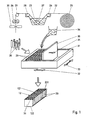
- Fig. 1 for the presented here Exemplary embodiment of the manufacturing process is illustrated, is a ceramic thread 22 produced by spinning, the Thread thickness can be reduced to approx. 10 ⁇ m in one Dip bath 22 coated with the plastic jacket 21.
- the Ceramic thread 22 by means of a pair of drive rollers 24, which press against the ceramic thread 22 by withdrawn from a supply roll 25 and by means of deflection rollers 26 - 29 out through the immersion bath 23, in the by suitable Movement on the ceramic thread 22 of the plastic jacket 21 High temperature plastic in a constant layer thickness is deposited.
- the covered ceramic thread 22 is behind the drive rollers 24 by means of a cutting knife 30 in the required length for the ceramic elements 11 with something Cut off excess.
- the separated and in a hot Oil bath polarized thread sections then form the coated ceramic sticks 20.
- the ceramic thread used 22 can have a solid or hollow profile, which is arbitrarily round or is angular.
- the coated ceramic rods 20 become one-sided open, box-shaped container 31 supplied, which - as in Fig. 1 is indicated by arrows 32, 33 - shaking movements is exposed. Through these shaking movements in the essentially upright, encased Ceramic sticks 20 standing upright in the container 31 packaged, as shown in Fig. 1. To do that Filling the container 31 with ceramic sticks 20, the is comparable to the automated packaging of Cigarettes in a packet of cigarettes, regardless of the To reliably design the size of the container 31 is by means of one displaceable in the container 31 in the direction of arrow 34 Partition 35 only ever a portion of the container 31 released for filling. The coated ceramic sticks 20 are fed directly to the partition 35, and the partition 35 becomes with increasing number of filled, coated ceramic rods 20 in the direction Arrow 34 moved until container 31 is completely filled is.
- the container 31 is now increasing Casting with a plastic 36, e.g. a resin or a Polyurethane (PU), filled, the plastic 36 the between the adjacent, covered ceramic rods 20 existing cavities completely filled and one solid Connection with the plastic jackets 21 of the sheathed Manufactures ceramic sticks 20.
- a plastic 36 e.g. a resin or a Polyurethane (PU)
- Fig. 4th To accelerate the filling process of the container 31 with coated ceramic rods 20 can - as shown in Fig. 4th is shown - the open top of the container 31 with a shadow mask 37 are covered, the holes 38 a compared to the cross section of the coated ceramic rods 20 have a slightly larger hole cross-section. The holes 38 are again arranged in rows and rows in a matrix give the position of the coated ceramic rods 20 in the container 31 before.
- the coated ceramic rods 20 are now filled into the container 31 via the shadow mask 37, wherein the orientation and arrangement of the coated ceramic rods 20 in the container 31 by the also the shaking movements (Arrows 32, 33) exposed shadow mask 37 already predetermined becomes.
- the Hole mask 37 To fill the plastic 36 with the coated ceramic rod 20 filled container 31 is the Hole mask 37 removed.
- the invention is not based on the above Embodiment limited, so - unlike in Fig. 1 is shown above - for the manufacture of the jacketed Ceramic sticks 20 from that made by spinning Ceramic thread 22 thread sections in the required length of Ceramic sticks 20 are cut off with a little oversize.
- the cut thread sections are polarized and then by moving in an immersion bath 23 by applying a Plastic layer of constant layer thickness with the Provided plastic jacket 21. This way produced coated plastic rods 20 are then - as described above and shown in Fig. 1 - to the Composite body 12 processed.
- coated ceramic rods 20 can also be larger in cross-section Ceramic rods with a diameter in the millimeter range be used. This too to the prescribed length Ceramic rods cut with a little oversize are used Movement in an immersion bath with the plastic jacket provided constant thickness, the thickness again selected according to the fill factor of the composite body 12 becomes.
- the Cross-sectional dimensioning of the ceramic elements 11 the cross-section of the ceramic sticks 20 or ceramic sticks on the light ones Cross section of the container 31 adapted that in the Composite body 12 one for the desired one Working frequency range of the ultrasonic transducer optimized Ratio of ceramic and plastic material is achieved. With a relatively large working frequency range Ultrasonic transducer with a center frequency of approx. 100 kHz for example, the fill factor of the composite body 12 with Ceramic material set at 40 - 60%.
- the dimensions of the container 31 are preferably so chosen to match the given dimensions of the Composite body 12 correspond, so that the nominal frequency ground composite body 12 only with the electrodes 13, 14 must be coated, as shown in Fig. 3 is.
- the container 31 can be a fixed standard size have, so that by the described manufacturing process Composite body 12 is always supplied in fixed dimensions. The individually requested dimensions are then by Cutting or sawing the composite body 12 realized, and the composite body 12 processed in this way is joined to the electrodes 13, 14 completed.
- the ultrasound transducer shown in section in FIG. 3 represents an electroacoustic transducer element that usually with similar, further converter elements a larger arrangement called a base or array arranged equidistantly arranged transducer elements becomes.
- the horizontal and vertical opening angle of the Transducer elements are the length and width of the Composite body 12 determines, and the working frequency of Transducer element is determined by the height between top and Bottom side 121, 122 of the composite body 12 are predetermined.
- usual Lengths and width dimensions of the composite body 12 are between 1 and 50 mm.
- a plurality of such converter elements can be realized if the length and made the width dimension of the composite body 12 larger and the electrodes 13, 14 are structured so that only Groups of ceramic rods 20 are contacted on the end face.
- the coating of the composite body 12 with the electrodes 131 134 on its top 121 and with the electrodes 141 144 on the underside 122 can be made as shown schematically in Fig. 5.
- this linear structuring of the electrodes 13, 14 can depending on the application, other structures, e.g. an annular, come into consideration.
Landscapes
- Engineering & Computer Science (AREA)
- Mechanical Engineering (AREA)
- Transducers For Ultrasonic Waves (AREA)
- Surgical Instruments (AREA)
- Pressure-Spray And Ultrasonic-Wave- Spray Burners (AREA)
Abstract
Description
- Fig. 1
- eine schematisierte Darstellung des Verfahrensablaufs bei der Herstellung eines Ultraschallwandlers,
- Fig. 2
- ausschnittweise eine Draufsicht eines nach dem Verfahren in Fig. 1 hergestellten Verbundkörpers des Ultraschallwandlers,
- Fig. 3
- ausschnittweise einen Schnitt des endgefertigten, kompletten Ultraschallwandlers gemäß Schnittlinie III - III in Fig. 2,
- Fig. 4
- eine Modifikation des Herstellungsverfahrens gemäß Fig. 1,
- Fig. 5
- ausschnittweise eine perspektivische Draufsicht eines Ultraschallwandlers gemäß einem weiteren Ausführungsbeispiel.
Claims (10)
- Verfahren zur Herstellung eines Ultraschallwandlers, der einen Verbundkörper (12) aus Kunststoff mit einer Vielzahl von eingebetteten, zwischen dessen Ober- und Unterseite (121, 122) sich erstreckenden Keramikelementen (11) aus piezoelektrischer oder elektrostriktiver Keramik und Elektroden (13, 14) aufweist, die auf der Ober- und Unterseite (121, 122) des Verbundkörpers (12) die Keramikelemente (11) kontaktieren, gekennzeichnet durch folgende Verfahrensschritte:die Keramikelemente (11) werden als mit einem Kunststoffmantel (21) konstanter Dicke ummantelte Keramikstäbchen (20) gefertigt,die ummantelten Keramikstäbchen (20) werden einem einseitig offenen, Rüttelbewegungen (32, 33) ausgesetzten Behälter (31) zugeführt und darin durch die Rüttelbewegungen aufrechtstehend paketiert,der mit den ummantelten Keramikstäbchen (20) gefüllte Behälter (31) wird im steigenden Guß mit einem Kunststoff (36), z.B. Harz oder Polyurethan, aufgefüllt,der dadurch entstehende Verbundkörper (12) wird nach Aushärten dem Behälter (31) entnommen und auf seiner Ober- und/oder Unterseite (121, 122) soweit abgeschliffen, bis die Keramikstäbchen (20) eine durch die Arbeitsfrequenz des Ultraschallwandlers bestimmte Länge aufweisen unddie Elektroden (13, 14) werden auf die Ober- und Unterseite (121, 122) des Verbundkörpers (12) so aufgebracht, daß sie alle oder nur Gruppen von Keramikstäbchen (12) kontaktieren.
- Verfahren nach Anspruch 1, dadurch gekennzeichnet, daß die Innenabmessungen des Behälters (31) entsprechend den gewünschten Abmessungen des Verbundkörpers (12) festgelegt werden.
- Verfahren nach Anspruch 1, dadurch gekennzeichnet, daß die Innenabmessungen des Behälters (31) unabhängig von den Abmessungen des Verbundkörpers (12) festgelegt werden und daß die Form des Verbundkörpers (12) anschließend zugeschnitten wird.
- Verfahren nach einem der Ansprüche 1 - 3, dadurch gekennzeichnet, daß der den Rüttelbewegungen ausgesetzte Behälter (31) mit einer die Lage der ummantelten Keramikstäbchen (20) im Behälter (31) vorgebenden Lochmaske (37) abgedeckt wird, deren Löcher (38) einen gegenüber dem Querschnitt der ummantelten Keramikstäbchen (20) etwas größeren Lochquerschnitt aufweisen, und daß die Lochmaske (37) vor Einfüllen des Kunststoffs (36) entfernt wird.
- Verfahren nach einem der Ansprüche 1 - 4, dadurch gekennzeichnet, daß die ummantelten Keramikstäbchen (20) von durch Spinnen hergestellten Keramikfäden (22), die in einem Tauchbad (23) mit einer Kunststoffschicht konstanter Schichtdicke ummantelt werden, in der geforderten Länge mit Übermaß abgeschnitten werden.
- Verfahren nach einem der Ansprüche 1 - 4, dadurch gekennzeichnet, daß zur Fertigung der ummantelten Keramikstäbchen (20) von durch Spinnen hergestellten Keramikfäden (22) Fadenabschnitte in der geforderten Länge mit Übermaß abgeschnitten und durch Bewegen in einem Tauchbad (23) mit dem Kunststoffmantel (21) versehen werden.
- Verfahren nach einem der Ansprüche 1 - 6, dadurch gekennzeichnet, daß der Querschnitt der Keramikstäbchen (20) an den lichten Querschnitt des Behälters (31) so angepaßt wird, daß im Verbundkörper (12) ein für den Arbeitsbfrequenzbereich des Ultraschallwandlers optimiertes Verhältnis von Keramik- und Kunststoffmaterial erzielt wird.
- Verfahren nach Anspruch 7, dadurch gekennzeichnet, daß der Querschnitt der Keramikstäbchen (20) unter Berücksichtigung der erforderlichen, durch die Dicke der Kunststoffmäntel (21) vorgegeben, gegenseitigen Abstände so gewählt wird, daß der Füllfaktor des Keramikmaterials im Verbundkörper (12) 40 - 60 % beträgt.
- Ultraschallwandler mit einem Verbundkörper (12) aus Kunststoff, der eine Vielzahl von im Kunststoff eingebetteten, zwischen der Ober- und Unterseite (121, 122) des Verbundkörpers (12) sich erstreckenden Keramikelemente (11) aus piezoelektrischer oder elektrostriktiver Keramik aufweist, und mit Elektroden (13, 14), die auf der Ober- und Unterseite (121, 122) des Verbundkörpers (12) die Keramikelemente (12) kontaktieren, dadurch gekennzeichnet, daß die Keramikelemente (11) durch Vorfertigung mit einem Kunststoffmantel (21) konstanter Dicke versehene, ummantelte Keramikstäbchen (20) sind, die unmittelbar aneinanderstoßend matrixartig aneinandergereiht sind, daß der zwischen den ummantelten Keramikstäbchen (20) verbleibende Freiraum durch einen Kunststoff, z.B. Harz oder Polyurethan, ausgefüllt ist und daß die Elektroden (13, 14) alle oder nur Gruppen von ummantelten Keramikstäbchen (20) kontaktieren.
- Ultraschallwandler nach Anspruch 9, dadurch gekennzeichnet, daß die Querschnitte von Ummantelung und Keramik der ummantelten Keramikstäbchen (20) so aufeinander abgestimmt sind, daß der Verbundkörper (12) einen für den Arbeitsfrequenzbereich (Bandbreite) des Ultraschallwandlers optimalen Füllfaktor an Keramik aufweist.
Applications Claiming Priority (2)
| Application Number | Priority Date | Filing Date | Title |
|---|---|---|---|
| DE10052636A DE10052636B4 (de) | 2000-10-24 | 2000-10-24 | Verfahren zur Herstellung eines Ultraschallwandlers |
| DE10052636 | 2000-10-24 |
Publications (3)
| Publication Number | Publication Date |
|---|---|
| EP1201322A2 true EP1201322A2 (de) | 2002-05-02 |
| EP1201322A3 EP1201322A3 (de) | 2009-03-18 |
| EP1201322B1 EP1201322B1 (de) | 2010-03-03 |
Family
ID=7660849
Family Applications (1)
| Application Number | Title | Priority Date | Filing Date |
|---|---|---|---|
| EP01121973A Expired - Lifetime EP1201322B1 (de) | 2000-10-24 | 2001-09-13 | Verfahren zur Herstellung eines Ultraschallwandlers |
Country Status (5)
| Country | Link |
|---|---|
| US (1) | US6574842B2 (de) |
| EP (1) | EP1201322B1 (de) |
| AT (1) | ATE459431T1 (de) |
| DE (2) | DE10052636B4 (de) |
| DK (1) | DK1201322T3 (de) |
Families Citing this family (7)
| Publication number | Priority date | Publication date | Assignee | Title |
|---|---|---|---|---|
| US7867178B2 (en) * | 2003-02-26 | 2011-01-11 | Sanuwave, Inc. | Apparatus for generating shock waves with piezoelectric fibers integrated in a composite |
| DE10323493B3 (de) * | 2003-05-23 | 2004-07-15 | Atlas Elektronik Gmbh | Unterwasserantenne |
| US7082655B2 (en) * | 2003-12-18 | 2006-08-01 | Ge Inspection Technologies, Lp | Process for plating a piezoelectric composite |
| DE102005032212B3 (de) * | 2005-07-09 | 2006-10-19 | Atlas Elektronik Gmbh | Unterwasserantenne |
| FR2889403B1 (fr) * | 2005-07-29 | 2007-11-09 | Thales Sa | Procede de fabrication d'un transducteur acoutique |
| DE102006015493B4 (de) | 2006-04-03 | 2010-12-23 | Atlas Elektronik Gmbh | Elektroakustischer Wandler |
| US7812508B2 (en) * | 2008-02-06 | 2010-10-12 | Innowattech Ltd. | Power harvesting from railway; apparatus, system and method |
Family Cites Families (9)
| Publication number | Priority date | Publication date | Assignee | Title |
|---|---|---|---|---|
| WO1995003632A1 (en) | 1993-07-19 | 1995-02-02 | Fiber Materials, Inc. | Method of fabricating a piezocomposite material |
| US5539965A (en) | 1994-06-22 | 1996-07-30 | Rutgers, The University Of New Jersey | Method for making piezoelectric composites |
| US5592730A (en) | 1994-07-29 | 1997-01-14 | Hewlett-Packard Company | Method for fabricating a Z-axis conductive backing layer for acoustic transducers using etched leadframes |
| US6225728B1 (en) * | 1994-08-18 | 2001-05-01 | Agilent Technologies, Inc. | Composite piezoelectric transducer arrays with improved acoustical and electrical impedance |
| US5929337A (en) * | 1994-11-11 | 1999-07-27 | M & A Packaging Services Limited | Non-mechanical contact ultrasound system for monitoring contents of a moving container |
| JPH08323748A (ja) * | 1995-05-29 | 1996-12-10 | Toho Rayon Co Ltd | 成形材料及びその製造方法 |
| US5691960A (en) * | 1995-08-02 | 1997-11-25 | Materials Systems, Inc. | Conformal composite acoustic transducer panel and method of fabrication thereof |
| DE19743859C2 (de) * | 1997-10-04 | 2000-11-16 | Stn Atlas Elektronik Gmbh | Verfahren zur Herstellung eines Verbund-Ultraschallwandlers |
| EP1066119B1 (de) * | 1998-03-26 | 2004-11-24 | Exogen, Inc. | Gruppierungen von biegsamen wandlerelementen |
-
2000
- 2000-10-24 DE DE10052636A patent/DE10052636B4/de not_active Expired - Fee Related
-
2001
- 2001-09-13 AT AT01121973T patent/ATE459431T1/de not_active IP Right Cessation
- 2001-09-13 EP EP01121973A patent/EP1201322B1/de not_active Expired - Lifetime
- 2001-09-13 DE DE50115369T patent/DE50115369D1/de not_active Expired - Lifetime
- 2001-09-13 DK DK01121973.0T patent/DK1201322T3/da active
-
2002
- 2002-01-17 US US10/047,111 patent/US6574842B2/en not_active Expired - Fee Related
Also Published As
| Publication number | Publication date |
|---|---|
| ATE459431T1 (de) | 2010-03-15 |
| EP1201322B1 (de) | 2010-03-03 |
| US20020063495A1 (en) | 2002-05-30 |
| DK1201322T3 (da) | 2010-05-17 |
| EP1201322A3 (de) | 2009-03-18 |
| DE10052636B4 (de) | 2004-07-08 |
| US6574842B2 (en) | 2003-06-10 |
| DE50115369D1 (de) | 2010-04-15 |
| DE10052636A1 (de) | 2002-05-08 |
Similar Documents
| Publication | Publication Date | Title |
|---|---|---|
| DE2802237C2 (de) | Spritzgießform zum Herstellen von aus mindestens zwei verschiedenen Kunststoffmassen bestehenden und mindestens zwei unterschiedliche Bereiche aufweisenden Spritzgußteilen | |
| DE3148319C2 (de) | Tintenstrahlschreibkopf und Verfahren zur Herstellung eines solchen Tintenstrahlschreibkopfes | |
| DE3102728C2 (de) | Verfahren zum Herstellen von Bauelementen aus Leichtbeton, insbesondere Gasbeton | |
| EP1201322B1 (de) | Verfahren zur Herstellung eines Ultraschallwandlers | |
| CH664552A5 (de) | Keramischer koerper sowie verfahren und form zur herstellung desselben. | |
| DE2628327B2 (de) | Verfahren und Vorrichtung zum Herstellen von Mehrschichtkondensatoren | |
| DE19741081C1 (de) | Verfahren zum Herstellen einer Antennenlinse | |
| EP1564336A1 (de) | Thermisch isolierendes Bauelement | |
| EP4100235B1 (de) | Verfahren zur additiven fertigung eines bauteils unter nutzung wenigstens einer mit füllmaterial zu füllenden volumenkammer | |
| DE19743859C2 (de) | Verfahren zur Herstellung eines Verbund-Ultraschallwandlers | |
| DE1614834C2 (de) | Verfahren zum Herstellen einer Halb leiteranordnung | |
| DE1729027A1 (de) | Vorrichtung zur Herstellung von Formlingen mit wabenartiger Struktur | |
| EP0316653A2 (de) | Beton-Palisade sowie Verfahren und Vorrichtung zum Herstellen derselben | |
| EP1565295A1 (de) | Anordnung zur herstellung von betonformsteinen | |
| DE102019007023B4 (de) | Strukturbauteil und Verfahren zu dessen Herstellung | |
| DE1942226A1 (de) | Verfahren zur Herstellung von sogenannten Sandwichelementen aus Leichtbeton | |
| DE804775C (de) | Verfahren und Form zum Herstellen von Baubloecken aus Beton u. dgl. | |
| EP1046486A1 (de) | Formwerkzeug zur Herstellung von mehreren montagegespritzten Bauteilen | |
| DE102006046217B3 (de) | Verfahren und Vorrichtung zur Herstellung von Keramikstapeln mit vieleckigem Querschnitt | |
| EP3846987A1 (de) | Vorrichtung zur herstellung von betonsteinen | |
| DE19804729A1 (de) | Baustein, insbesondere auf der Basis zementgebundenen Blähtons | |
| DE10118061A1 (de) | Kapazitives Sensorelement und Verfahren zur Herstellung eines kapazitiven Sensorelements | |
| DE19650885B4 (de) | Verfahren zur Herstellung von Keramik-Polymer-Verbunden | |
| DE3616976A1 (de) | Anordnung zum herstellen von pinsel- und buerstenbuendeln aus kuenstlichem oder natuerlichem besteckungsmaterial | |
| WO1999055476A1 (de) | Vorrichtung und verfahren zum giessen von dreidimensional strukturierten gegenständen |
Legal Events
| Date | Code | Title | Description |
|---|---|---|---|
| PUAI | Public reference made under article 153(3) epc to a published international application that has entered the european phase |
Free format text: ORIGINAL CODE: 0009012 |
|
| AK | Designated contracting states |
Kind code of ref document: A2 Designated state(s): AT BE CH CY DE DK ES FI FR GB GR IE IT LI LU MC NL PT SE TR |
|
| AX | Request for extension of the european patent |
Free format text: AL;LT;LV;MK;RO;SI |
|
| RAP1 | Party data changed (applicant data changed or rights of an application transferred) |
Owner name: ATLAS ELEKTRONIK GMBH |
|
| PUAL | Search report despatched |
Free format text: ORIGINAL CODE: 0009013 |
|
| AK | Designated contracting states |
Kind code of ref document: A3 Designated state(s): AT BE CH CY DE DK ES FI FR GB GR IE IT LI LU MC NL PT SE TR |
|
| AX | Request for extension of the european patent |
Extension state: AL LT LV MK RO SI |
|
| 17P | Request for examination filed |
Effective date: 20090428 |
|
| GRAP | Despatch of communication of intention to grant a patent |
Free format text: ORIGINAL CODE: EPIDOSNIGR1 |
|
| GRAS | Grant fee paid |
Free format text: ORIGINAL CODE: EPIDOSNIGR3 |
|
| AKX | Designation fees paid |
Designated state(s): AT BE CH CY DE DK ES FI FR GB GR IE IT LI LU MC NL PT SE TR |
|
| GRAA | (expected) grant |
Free format text: ORIGINAL CODE: 0009210 |
|
| AK | Designated contracting states |
Kind code of ref document: B1 Designated state(s): AT BE CH CY DE DK ES FI FR GB GR IE IT LI LU MC NL PT SE TR |
|
| REG | Reference to a national code |
Ref country code: GB Ref legal event code: FG4D Free format text: NOT ENGLISH |
|
| REG | Reference to a national code |
Ref country code: CH Ref legal event code: EP |
|
| REG | Reference to a national code |
Ref country code: IE Ref legal event code: FG4D |
|
| REF | Corresponds to: |
Ref document number: 50115369 Country of ref document: DE Date of ref document: 20100415 Kind code of ref document: P |
|
| REG | Reference to a national code |
Ref country code: DK Ref legal event code: T3 |
|
| REG | Reference to a national code |
Ref country code: NL Ref legal event code: VDEP Effective date: 20100303 |
|
| PG25 | Lapsed in a contracting state [announced via postgrant information from national office to epo] |
Ref country code: FI Free format text: LAPSE BECAUSE OF FAILURE TO SUBMIT A TRANSLATION OF THE DESCRIPTION OR TO PAY THE FEE WITHIN THE PRESCRIBED TIME-LIMIT Effective date: 20100303 |
|
| REG | Reference to a national code |
Ref country code: IE Ref legal event code: FD4D |
|
| PG25 | Lapsed in a contracting state [announced via postgrant information from national office to epo] |
Ref country code: IE Free format text: LAPSE BECAUSE OF FAILURE TO SUBMIT A TRANSLATION OF THE DESCRIPTION OR TO PAY THE FEE WITHIN THE PRESCRIBED TIME-LIMIT Effective date: 20100303 Ref country code: SE Free format text: LAPSE BECAUSE OF FAILURE TO SUBMIT A TRANSLATION OF THE DESCRIPTION OR TO PAY THE FEE WITHIN THE PRESCRIBED TIME-LIMIT Effective date: 20100303 Ref country code: CY Free format text: LAPSE BECAUSE OF FAILURE TO SUBMIT A TRANSLATION OF THE DESCRIPTION OR TO PAY THE FEE WITHIN THE PRESCRIBED TIME-LIMIT Effective date: 20100303 Ref country code: ES Free format text: LAPSE BECAUSE OF FAILURE TO SUBMIT A TRANSLATION OF THE DESCRIPTION OR TO PAY THE FEE WITHIN THE PRESCRIBED TIME-LIMIT Effective date: 20100614 Ref country code: GR Free format text: LAPSE BECAUSE OF FAILURE TO SUBMIT A TRANSLATION OF THE DESCRIPTION OR TO PAY THE FEE WITHIN THE PRESCRIBED TIME-LIMIT Effective date: 20100604 Ref country code: NL Free format text: LAPSE BECAUSE OF FAILURE TO SUBMIT A TRANSLATION OF THE DESCRIPTION OR TO PAY THE FEE WITHIN THE PRESCRIBED TIME-LIMIT Effective date: 20100303 |
|
| PLBE | No opposition filed within time limit |
Free format text: ORIGINAL CODE: 0009261 |
|
| STAA | Information on the status of an ep patent application or granted ep patent |
Free format text: STATUS: NO OPPOSITION FILED WITHIN TIME LIMIT |
|
| PG25 | Lapsed in a contracting state [announced via postgrant information from national office to epo] |
Ref country code: PT Free format text: LAPSE BECAUSE OF FAILURE TO SUBMIT A TRANSLATION OF THE DESCRIPTION OR TO PAY THE FEE WITHIN THE PRESCRIBED TIME-LIMIT Effective date: 20100705 |
|
| 26N | No opposition filed |
Effective date: 20101206 |
|
| BERE | Be: lapsed |
Owner name: ATLAS ELEKTRONIK G.M.B.H. Effective date: 20100930 |
|
| PG25 | Lapsed in a contracting state [announced via postgrant information from national office to epo] |
Ref country code: IT Free format text: LAPSE BECAUSE OF FAILURE TO SUBMIT A TRANSLATION OF THE DESCRIPTION OR TO PAY THE FEE WITHIN THE PRESCRIBED TIME-LIMIT Effective date: 20100303 |
|
| PG25 | Lapsed in a contracting state [announced via postgrant information from national office to epo] |
Ref country code: MC Free format text: LAPSE BECAUSE OF NON-PAYMENT OF DUE FEES Effective date: 20100930 |
|
| REG | Reference to a national code |
Ref country code: CH Ref legal event code: PL |
|
| PG25 | Lapsed in a contracting state [announced via postgrant information from national office to epo] |
Ref country code: LI Free format text: LAPSE BECAUSE OF NON-PAYMENT OF DUE FEES Effective date: 20100930 Ref country code: BE Free format text: LAPSE BECAUSE OF NON-PAYMENT OF DUE FEES Effective date: 20100930 Ref country code: CH Free format text: LAPSE BECAUSE OF NON-PAYMENT OF DUE FEES Effective date: 20100930 |
|
| PGFP | Annual fee paid to national office [announced via postgrant information from national office to epo] |
Ref country code: DK Payment date: 20110926 Year of fee payment: 11 |
|
| PG25 | Lapsed in a contracting state [announced via postgrant information from national office to epo] |
Ref country code: AT Free format text: LAPSE BECAUSE OF NON-PAYMENT OF DUE FEES Effective date: 20100913 |
|
| PG25 | Lapsed in a contracting state [announced via postgrant information from national office to epo] |
Ref country code: LU Free format text: LAPSE BECAUSE OF NON-PAYMENT OF DUE FEES Effective date: 20100913 |
|
| PG25 | Lapsed in a contracting state [announced via postgrant information from national office to epo] |
Ref country code: TR Free format text: LAPSE BECAUSE OF FAILURE TO SUBMIT A TRANSLATION OF THE DESCRIPTION OR TO PAY THE FEE WITHIN THE PRESCRIBED TIME-LIMIT Effective date: 20100303 |
|
| PGFP | Annual fee paid to national office [announced via postgrant information from national office to epo] |
Ref country code: GB Payment date: 20120920 Year of fee payment: 12 |
|
| PGFP | Annual fee paid to national office [announced via postgrant information from national office to epo] |
Ref country code: DE Payment date: 20120921 Year of fee payment: 12 |
|
| PGFP | Annual fee paid to national office [announced via postgrant information from national office to epo] |
Ref country code: FR Payment date: 20121010 Year of fee payment: 12 |
|
| REG | Reference to a national code |
Ref country code: DE Ref legal event code: R082 Ref document number: 50115369 Country of ref document: DE Representative=s name: , |
|
| REG | Reference to a national code |
Ref country code: DK Ref legal event code: EBP |
|
| PG25 | Lapsed in a contracting state [announced via postgrant information from national office to epo] |
Ref country code: DK Free format text: LAPSE BECAUSE OF NON-PAYMENT OF DUE FEES Effective date: 20121001 |
|
| GBPC | Gb: european patent ceased through non-payment of renewal fee |
Effective date: 20130913 |
|
| REG | Reference to a national code |
Ref country code: DE Ref legal event code: R119 Ref document number: 50115369 Country of ref document: DE Effective date: 20140401 |
|
| REG | Reference to a national code |
Ref country code: FR Ref legal event code: ST Effective date: 20140530 |
|
| PG25 | Lapsed in a contracting state [announced via postgrant information from national office to epo] |
Ref country code: GB Free format text: LAPSE BECAUSE OF NON-PAYMENT OF DUE FEES Effective date: 20130913 |
|
| PG25 | Lapsed in a contracting state [announced via postgrant information from national office to epo] |
Ref country code: DE Free format text: LAPSE BECAUSE OF NON-PAYMENT OF DUE FEES Effective date: 20140401 Ref country code: FR Free format text: LAPSE BECAUSE OF NON-PAYMENT OF DUE FEES Effective date: 20130930 |