EP1200241B1 - Repartiteur d'ecoulement selectif pour fluides a viscosite elevee - Google Patents
Repartiteur d'ecoulement selectif pour fluides a viscosite elevee Download PDFInfo
- Publication number
- EP1200241B1 EP1200241B1 EP00943883A EP00943883A EP1200241B1 EP 1200241 B1 EP1200241 B1 EP 1200241B1 EP 00943883 A EP00943883 A EP 00943883A EP 00943883 A EP00943883 A EP 00943883A EP 1200241 B1 EP1200241 B1 EP 1200241B1
- Authority
- EP
- European Patent Office
- Prior art keywords
- valve
- product
- housing
- line
- valves
- Prior art date
- Legal status (The legal status is an assumption and is not a legal conclusion. Google has not performed a legal analysis and makes no representation as to the accuracy of the status listed.)
- Expired - Lifetime
Links
- 239000012530 fluid Substances 0.000 title 1
- 239000007788 liquid Substances 0.000 claims abstract description 6
- 235000001674 Agaricus brunnescens Nutrition 0.000 claims description 6
- 230000001154 acute effect Effects 0.000 claims description 3
- 238000013022 venting Methods 0.000 claims description 2
- 239000007789 gas Substances 0.000 claims 2
- 239000012752 auxiliary agent Substances 0.000 claims 1
- 238000007599 discharging Methods 0.000 claims 1
- 230000007717 exclusion Effects 0.000 claims 1
- 239000000047 product Substances 0.000 description 72
- 229920000642 polymer Polymers 0.000 description 14
- 238000006073 displacement reaction Methods 0.000 description 7
- 230000007062 hydrolysis Effects 0.000 description 7
- 238000006460 hydrolysis reaction Methods 0.000 description 7
- IJGRMHOSHXDMSA-UHFFFAOYSA-N Atomic nitrogen Chemical compound N#N IJGRMHOSHXDMSA-UHFFFAOYSA-N 0.000 description 4
- -1 Polyethylene terephthalate Polymers 0.000 description 3
- 230000015572 biosynthetic process Effects 0.000 description 3
- 238000010438 heat treatment Methods 0.000 description 3
- 238000000354 decomposition reaction Methods 0.000 description 2
- 238000009795 derivation Methods 0.000 description 2
- 230000006855 networking Effects 0.000 description 2
- 229910052757 nitrogen Inorganic materials 0.000 description 2
- 229920002292 Nylon 6 Polymers 0.000 description 1
- 239000004952 Polyamide Substances 0.000 description 1
- 239000006227 byproduct Substances 0.000 description 1
- 238000004140 cleaning Methods 0.000 description 1
- 239000003245 coal Substances 0.000 description 1
- 238000010276 construction Methods 0.000 description 1
- 229920001577 copolymer Polymers 0.000 description 1
- 230000006735 deficit Effects 0.000 description 1
- 238000005315 distribution function Methods 0.000 description 1
- 230000000694 effects Effects 0.000 description 1
- 238000005516 engineering process Methods 0.000 description 1
- 230000002349 favourable effect Effects 0.000 description 1
- 238000011010 flushing procedure Methods 0.000 description 1
- 239000013529 heat transfer fluid Substances 0.000 description 1
- 230000003301 hydrolyzing effect Effects 0.000 description 1
- 230000014759 maintenance of location Effects 0.000 description 1
- 238000004519 manufacturing process Methods 0.000 description 1
- 239000000463 material Substances 0.000 description 1
- 229920002647 polyamide Polymers 0.000 description 1
- 229920001707 polybutylene terephthalate Polymers 0.000 description 1
- 229920000515 polycarbonate Polymers 0.000 description 1
- 239000004417 polycarbonate Substances 0.000 description 1
- 229920000139 polyethylene terephthalate Polymers 0.000 description 1
- 239000005020 polyethylene terephthalate Substances 0.000 description 1
- 229920000098 polyolefin Polymers 0.000 description 1
- 230000002035 prolonged effect Effects 0.000 description 1
- 238000009423 ventilation Methods 0.000 description 1
Images

Classifications
-
- F—MECHANICAL ENGINEERING; LIGHTING; HEATING; WEAPONS; BLASTING
- F16—ENGINEERING ELEMENTS AND UNITS; GENERAL MEASURES FOR PRODUCING AND MAINTAINING EFFECTIVE FUNCTIONING OF MACHINES OR INSTALLATIONS; THERMAL INSULATION IN GENERAL
- F16K—VALVES; TAPS; COCKS; ACTUATING-FLOATS; DEVICES FOR VENTING OR AERATING
- F16K11/00—Multiple-way valves, e.g. mixing valves; Pipe fittings incorporating such valves
- F16K11/10—Multiple-way valves, e.g. mixing valves; Pipe fittings incorporating such valves with two or more closure members not moving as a unit
- F16K11/20—Multiple-way valves, e.g. mixing valves; Pipe fittings incorporating such valves with two or more closure members not moving as a unit operated by separate actuating members
-
- Y—GENERAL TAGGING OF NEW TECHNOLOGICAL DEVELOPMENTS; GENERAL TAGGING OF CROSS-SECTIONAL TECHNOLOGIES SPANNING OVER SEVERAL SECTIONS OF THE IPC; TECHNICAL SUBJECTS COVERED BY FORMER USPC CROSS-REFERENCE ART COLLECTIONS [XRACs] AND DIGESTS
- Y10—TECHNICAL SUBJECTS COVERED BY FORMER USPC
- Y10T—TECHNICAL SUBJECTS COVERED BY FORMER US CLASSIFICATION
- Y10T137/00—Fluid handling
- Y10T137/8593—Systems
- Y10T137/877—With flow control means for branched passages
- Y10T137/87877—Single inlet with multiple distinctly valved outlets
Definitions
- the invention relates to an interchangeable distributor for highly viscous Liquids, which is a central distribution space in which has a product line I and two product valves, each of the product valves consisting of a guide cylinder Housing with a branching on the side Product line II and a housing extension on the Branch of the product line II opposite side, as well a valve piston with valve head that can move in the axial direction in the housing, the one in the closed position in one in the wall valve seat embedded in the central distribution area engages and optionally there is an auxiliary valve.
- the invention relates to a device for mutual distribution from polymer melt to two mutually operated treatment units, such as two polymer filters or processing extruders and granulators.
- valves of the product manifold according to US Pat. No. 5,269,348 an expanded on one side, housing designed as a guide cylinder with a branched product drain and a housing extension on the the branch on the opposite side of the product derivation, as well as an im Housing in the axial direction movable valve piston with a valve head that in closed position in a recessed in the wall of the product feed Valve seat engages.
- the valve head has a mushroom-shaped displacement attachment, which with the valve closed completely into the central distribution space Formation of a gap for the wall of the product flow Distribution space is positioned, and its shaft at the level of the open valve Branch of the product derivation is positioned to a flow evenly within the valve without dead space.
- JP-A-52063419 describes an exchange distributor which is a central one Distribution room has a product feed and two product valves open, the product valves being arranged in a Y-shape for the product feed line.
- Each of the product valves consists of a guide cylinder Housing with a laterally branching product derivative and an in Housing in the axial direction movable valve piston with valve head, which in engages closed position in a valve seat.
- the object of the present invention is to provide a changeable distributor at the beginning to change the type mentioned in such a way that, despite a constant reciprocal closed product valve the product flow completely evenly through the central distribution room and the second opened product valve flows, without formation of dead spaces, especially in the distribution area. Furthermore, decomposition or Networking of product residues in the closed valve be avoided as far as possible.
- the product valve housing (4) preferably has in the region of the Housing extension (5) on a valve seat (13) into which the valve head one within a housing designed as a guide cylinder movable valve piston of an auxiliary valve (10) in the closed Position engages, the housing of the auxiliary valve (10) optionally with closable lines (15) for ventilation and / or Product emptying and / or for feeding aids such as air or nitrogen or steam.
- the present invention is characterized in that it is the Avoids disadvantages of normal changeover or changeover valves.
- the Exchangeable distributor is far superior to conventional valves.
- Exchange distributor according to the invention with the following special features fitted:
- the piston and the The valve seat is structurally held so that it is soft and bumpless opening flow characteristic results.
- the opening characteristics of the Valve allows the distributors to be switched over fully automatically shape.
- the valve seat is one of the causes alongside the valve housing for the soft opening characteristics. Deliberately elongated Opening cone in the distributor housing and the selected tolerances allow the valve to open slowly without pressure surges.
- the mushroom-shaped displacement cap of the closed valve is like this set that he was across the center line into the opposite pipe space protrudes. So the mushroom head brings the straight short product passage Resistance and forces the main mass of the product, the longer way to slide along the housing wall. The blunt Angles favor this product guidance. This results in a perfect rinsing effect.
- the shaft became particularly favorable for wall flushing reduced in diameter at the base as far as possible.
- the bigger one Mushroom head moves the current further towards the foot of the mushroom. Also this design point serves to improve product flow management along the longer outer wall of the housing.
- the housing was designed so that the polymer flow is conducted.
- the Pressure differences are implemented with the built-in valve piston that a rinsing of all corners and edges is guaranteed.
- the position the product valves among themselves is optimized so that for the Polymer flow in the distribution room an optimal flow without Flow shadow is guaranteed.
- the angular position of preferred 120 ° to each other is an optimum based on the entire production of the Cabinet construction.
- the possible range of the angular position lies at 100 to 140 °.
- the product valves of the interchangeable distributor can be made in a manner known per se Way with auxiliary valves for venting and / or emptying and / or Be equipped with aids. Those are preferred Auxiliary valves arranged so that they run empty after actuation can. This is particularly advantageous if the highly viscous Liquid is a polymer melt that tends to charring. A Tangential attachment of the auxiliary valve to the product valve is common in many Cases appropriate.
- the interchangeable distributor according to the invention can be used for any viscous Liquid used by a single supply line is to be mutually distributed over two output lines or vice versa.
- a preferred application is the distribution of a Polymer melt.
- polymers are Polyethylene terephthalate, polypropylene terephthalate, Polybutylene terephthalate, polyamide 6, polyamide 6.6, polycarbonates, Polyolefins and copolymers thereof.
- Other Types of heating, such as heating tapes, can also be used become.
- Polymers have the unpleasant property of being hot to decompress unpressurized space into low and high viscosity materials. While the low-viscosity products become gaseous over time and disappear into the atmosphere, the highly viscous products carbonize. This coal formation ultimately leads to total blockage of the lines and valves. If a valve of the interchangeable distributor is switched off and for not used for a long time, it is recommended to use hydrolysis To clean the valve. Hydrolysis avoids this Charring of the product in the valve. Before the hydrolysis started the valve must be completely drained of polymer. The Vapor is unable to push the polymer out as it preferably a pressure of 1 to 2 bar absolute, particularly preferred 1.0 to 1.3 bar.
- the steam feed for hydrolysis expediently takes place via the in the main body of the product valves attached auxiliary valves. This allows hydrolysis to take place directly on the seat of the polymer valve begin. It must be for safe steam removal, possibly loaded with oligomeric hydrolysis products.
- the steam is removed via a vent connection of the auxiliary valve or via a corresponding drainage opening in product line II.
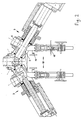
- Fig. 1 shows an interchangeable distributor consisting of the in the central Distribution room (1) opening product line I (2) and the two Product valves (3) (not fully shown).
- the Product lines II (6) are oriented down to 90 °.
- the right Product valve (3) is in the closed position and the left one in open valve position shown.
- the product valves (3) themselves correspond with the exception of the geometry of the mushroom-shaped Displacer attachment (11), that of US Pat. No. 5,269,348.
- the housing (4) is on the branch of product line II (6) opposite side expanded (5), so that in cooperation of the Extension (5) with the displacement attachment (11) the main product flow deflected and evenly over the entire cross-section of the valve and thus on the entire cross section of the output line (6) is distributed.
- the valve piston (7) guided in the housing (4) carries the valve head (8), which in the closed position in the Valve housing seat (9) engages with an elongated opening cone.
- the Valve head (8) carries a mushroom-shaped described in Fig. 3 Displacement attachment (11), which is in the closed valve position is completely positioned in the distribution space (1), with between the Displacer attachment (11) and the wall of the distribution space (1) only a gap (i) sufficient for the product flow remains.
- the displacement attachment (11) such as shown here, in the amount of the branch of product line II (6) to there to perform its congestion and distribution function.
- FIG. 2 shows a changeable distributor constructed in a similar way to FIG. 1.
- both product valves (3) are in the area of the housing expansion (5) each with an auxiliary valve (10).
- the auxiliary valve (10) are heated with heat transfer fluid.
- about the connection (15) can, if desired, air or nitrogen or Steam for hydrolysis of polymer residues can be fed.
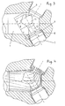
- Fig. 3 shows the geometry of the displacer attachment (11) and its position within the distribution space (1).
- This geometry of the displacer attachment (11) in conjunction with the geometry of the distribution space (1) and the y-shaped arrangement of product line I (2) and product valves (3) one over the entire Cross section of uniform product flow, as in Fig. 4 by arrows shown.
- the distribution space (1) does not have a vertical one surfaces or edges running towards the product flow, rather all surfaces and edges run at an acute or obtuse angle to the product flow.
- the center lines of the product valves (3) form one Angles from 100 to 140 °, preferably 120 ° to each other and from 50 to 70 ° to the center line of product line I (2).
- the product lines II (6) are preferably directed horizontally down to 90 ° vertically executed.
Landscapes
- Engineering & Computer Science (AREA)
- General Engineering & Computer Science (AREA)
- Mechanical Engineering (AREA)
- Lift Valve (AREA)
- Feeding, Discharge, Calcimining, Fusing, And Gas-Generation Devices (AREA)
- Multiple-Way Valves (AREA)
- Extrusion Moulding Of Plastics Or The Like (AREA)
- Pipe Accessories (AREA)
- Pipeline Systems (AREA)
- Coating Apparatus (AREA)
- Nozzles (AREA)
- Processing And Handling Of Plastics And Other Materials For Molding In General (AREA)
- Polysaccharides And Polysaccharide Derivatives (AREA)
Claims (7)
- Répartiteur alterné de liquides très visqueux, qui comporte une chambre (1) centrale de répartition dans laquelle débouche un conduit I (2) de produit et deux vannes (3) de produit, chacune des vannes (3) de produit étant constituée d'un corps (4) en forme de cylindre de guidage et ayant un conduit II (6) de produit en dérivation latérale et un élargissement (5) du corps du côté opposé à la dérivation du conduit II (6) de produit, ainsi qu'un piston (7) de vanne, mobile dans le corps en direction axiale et ayant une tête (8) de vanne qui, en position fermée, pénètre dans un siège (9) de vanne encastrée dans la paroi de la chambre (1) centrale de répartition et constitue au choix une vanne (10) auxiliaire,
dans lequel les deux vannes (3) de produit sont disposées en forme d'Y par rapport au conduit I (2) de produit, les lignes médianes des deux vannes (3) de produit faisant entre elles un angle de 100 à 140° et faisant un angle de 50 à 70° avec la ligne médiane du conduit I (2) de produit,
dans lequel la tête (8) de vanne a un chapeau (11) de refoulement en forme de champignon qui, lorsque la vanne est fermée, est en position complètement dans la chambre (1) centrale de répartition avec formation d'un intervalle (i), permettant un flux de produit, avec la paroi de la chambre du répartiteur et dont la tige (12), lorsque la vanne est ouverte, est en position au niveau de la dérivation du conduit II (6) de produit
dans lequel la chambre (1) centrale de répartition a, y compris le chapeau (11) de refoulement qui y est placé, seulement des surfaces et des bords qui font un angle aigu ou obtus avec le flux du produit, en excluant des surfaces ou des bords perpendiculaires au flux du produit,
et dans lequel les diamètres du piston (a) de vanne, du siège (b) de vanne, de la tige (c) et de la tête (d) en champignon du chapeau de refoulement sont tels que a : b : c = 1: (0,75 à 90) : (0,4 à 0,5) avec d = (0,90 à 0,99).b
et les hauteurs de la tête (e) de vanne, de la tige (f), de la partie (g) inférieure et de la partie (h) supérieure du capuchon du chapeau de refoulement en forme de champignon, ainsi que la largeur (i) de l'intervalle entre le chapeau et la paroi lorsque la vanne est fermée sont telles que e : f: g: h: i = (0,6 à 0,8) : (1,3 à 1,7) : 1 (0,95 à 1,05) : (0,2 à 0,35)
avec d = (0,9 à 1,1). (g + h)
e + f +g = (1, 0 à 1,05). t et t est le diamètre du conduit II de produit à la dérivation. - Répartiteur alterné suivant la revendication 1, caractérisé en ce que le siège (9) de vanne a un cône d'ouverture s'étendant en longueur.
- Répartiteur alterné suivant l'une des revendications 1 à 2, caractérisé en ce que le corps (4) de vanne du produit a, dans la zone de l'élargissement (5) du corps, un siège (13) de vanne, dans lequel pénètre, en position fermée, la tête de vanne d'un piston de vanne, mobile à l'intérieur d'un corps, constitué en cylindre de guidage, d'une vanne (10) auxiliaire, la vanne (10) auxiliaire étant reliée au choix à des conduits (15) qui peuvent être fermés de mise à l'atmosphère et/ou de vidange et/ou d'alimentation en agent auxiliaire.
- Répartiteur alterné suivant la revendication 3, caractérisé en ce que la vanne (10) auxiliaire est reliée à un conduit (5) d'alimentation en gaz ou en vapeur.
- Répartiteur alterné, suivant la revendication 4, caractérisé en ce que les gaz ou la vapeur passent, lorsque la vanne (10) auxiliaire est ouverte, dans le corps de la vanne auxiliaire et dans le corps de la vanne (13) de produit et en ressortent par des ouvertures d'évacuation.
- Répartiteur alterné suivant l'une des revendications 1 à 5, caractérisé en ce que le répartiteur alterné et, le cas échéant, la vanne auxiliaire peuvent être chauffés.
- Répartiteur alterné suivant l'une des revendications 1 à 6, caractérisé en ce que le liquide très visqueux est au choix apporté par le conduit I (2) de produit et évacué par les conduits II (6) de produit ou est apporté par les conduits II (6) de produit et est évacué par le conduit I (2) de produit.
Applications Claiming Priority (3)
| Application Number | Priority Date | Filing Date | Title |
|---|---|---|---|
| DE19928860 | 1999-06-24 | ||
| DE19928860A DE19928860A1 (de) | 1999-06-24 | 1999-06-24 | Wechselverteiler für hochviskose Flüssigkeiten |
| PCT/EP2000/005875 WO2001000384A1 (fr) | 1999-06-24 | 2000-06-23 | Repartiteur d'ecoulement selectif pour fluides a viscosite elevee |
Publications (2)
| Publication Number | Publication Date |
|---|---|
| EP1200241A1 EP1200241A1 (fr) | 2002-05-02 |
| EP1200241B1 true EP1200241B1 (fr) | 2004-05-12 |
Family
ID=7912325
Family Applications (1)
| Application Number | Title | Priority Date | Filing Date |
|---|---|---|---|
| EP00943883A Expired - Lifetime EP1200241B1 (fr) | 1999-06-24 | 2000-06-23 | Repartiteur d'ecoulement selectif pour fluides a viscosite elevee |
Country Status (11)
| Country | Link |
|---|---|
| US (1) | US6763852B1 (fr) |
| EP (1) | EP1200241B1 (fr) |
| JP (1) | JP2003503230A (fr) |
| KR (1) | KR100728404B1 (fr) |
| CN (1) | CN1264667C (fr) |
| AT (1) | ATE266517T1 (fr) |
| AU (1) | AU5819700A (fr) |
| DE (2) | DE19928860A1 (fr) |
| EA (1) | EA003050B1 (fr) |
| ES (1) | ES2219358T3 (fr) |
| WO (1) | WO2001000384A1 (fr) |
Families Citing this family (6)
| Publication number | Priority date | Publication date | Assignee | Title |
|---|---|---|---|---|
| GB2370454B (en) | 2000-12-20 | 2005-06-22 | Nokia Mobile Phones Ltd | Mobile telecommunications device |
| RU2388531C2 (ru) * | 2004-07-23 | 2010-05-10 | Базелль Полиолефин Италия С.Р.Л. | Способ выгрузки полимера из полимеризационного реактора |
| DE102009014029B4 (de) | 2009-03-23 | 2012-10-25 | Kreyenborg Verwaltungen Und Beteiligungen Gmbh & Co. Kg | Umschaltventil für eine Kunststoffschmelze |
| CN103047448B (zh) * | 2012-12-14 | 2015-04-15 | 山东恒远利废技术发展有限公司 | 膏体分配阀 |
| CN107165876B (zh) * | 2017-06-05 | 2019-06-14 | 北京玖鼎力源科技有限公司 | 一种二通液压阀 |
| US11815187B2 (en) * | 2022-01-26 | 2023-11-14 | Maag Germany Gmbh | 3-port valve |
Family Cites Families (10)
| Publication number | Priority date | Publication date | Assignee | Title |
|---|---|---|---|---|
| DE2444012C2 (de) * | 1974-09-14 | 1976-08-05 | Scheer & Cie C F | Vorrichtung zum Verarbeiten, insbesondere zum Extrudieren, von schmelzflüssigen Kunststoffen |
| JPS5263419A (en) * | 1975-11-20 | 1977-05-25 | Murata Machinery Ltd | Stop valve at separation point for polymer branched line |
| JPS5999176A (ja) * | 1982-08-11 | 1984-06-07 | Asuka Kogyo Kk | 切換弁 |
| JPH03168475A (ja) * | 1989-11-25 | 1991-07-22 | Fuji Techno Kogyo Kk | 混合弁 |
| JPH0563419A (ja) | 1991-08-30 | 1993-03-12 | Asahi Glass Co Ltd | 自動車用アンテナ |
| US5232023A (en) * | 1992-12-22 | 1993-08-03 | Tri-Clover, Inc. | Manifold valve assemblies |
| US5269348A (en) | 1993-03-12 | 1993-12-14 | Zimmer Aktiengesellschaft | Distributor for viscous fluids with adjustable multiple discharge |
| DE4409234A1 (de) | 1994-03-18 | 1995-09-21 | Zimmer Ag | Verteiler für viskose Flüssigkeiten mit multiplen radialen Ausgängen |
| DE19649013B4 (de) | 1996-11-27 | 2006-03-09 | Zimmer Ag | Verfahren zur Reinigung einer Polymerschmelze-Filtrationsvorrichtung |
| US6397887B1 (en) * | 2001-03-12 | 2002-06-04 | Itt Industries Pure-Flo Solutions Group | Valve housing with integral downstream purge |
-
1999
- 1999-06-24 DE DE19928860A patent/DE19928860A1/de not_active Withdrawn
-
2000
- 2000-06-23 AT AT00943883T patent/ATE266517T1/de not_active IP Right Cessation
- 2000-06-23 CN CNB00809375XA patent/CN1264667C/zh not_active Expired - Lifetime
- 2000-06-23 JP JP2001506075A patent/JP2003503230A/ja active Pending
- 2000-06-23 WO PCT/EP2000/005875 patent/WO2001000384A1/fr active IP Right Grant
- 2000-06-23 AU AU58197/00A patent/AU5819700A/en not_active Abandoned
- 2000-06-23 ES ES00943883T patent/ES2219358T3/es not_active Expired - Lifetime
- 2000-06-23 KR KR1020017016585A patent/KR100728404B1/ko not_active IP Right Cessation
- 2000-06-23 EP EP00943883A patent/EP1200241B1/fr not_active Expired - Lifetime
- 2000-06-23 DE DE50006423T patent/DE50006423D1/de not_active Expired - Lifetime
- 2000-06-23 EA EA200200038A patent/EA003050B1/ru not_active IP Right Cessation
- 2000-06-23 US US10/018,833 patent/US6763852B1/en not_active Expired - Lifetime
Also Published As
| Publication number | Publication date |
|---|---|
| EA003050B1 (ru) | 2002-12-26 |
| DE50006423D1 (de) | 2004-06-17 |
| AU5819700A (en) | 2001-01-31 |
| ATE266517T1 (de) | 2004-05-15 |
| EP1200241A1 (fr) | 2002-05-02 |
| DE19928860A1 (de) | 2000-12-28 |
| WO2001000384A1 (fr) | 2001-01-04 |
| ES2219358T3 (es) | 2004-12-01 |
| CN1264667C (zh) | 2006-07-19 |
| KR100728404B1 (ko) | 2007-06-13 |
| US6763852B1 (en) | 2004-07-20 |
| CN1359326A (zh) | 2002-07-17 |
| JP2003503230A (ja) | 2003-01-28 |
| KR20020023964A (ko) | 2002-03-29 |
| EA200200038A1 (ru) | 2002-06-27 |
Similar Documents
| Publication | Publication Date | Title |
|---|---|---|
| DE1729136A1 (de) | Siebauswechselvorrichtung | |
| EP2576180B1 (fr) | Dispositif de filtration pour matériau visqueux | |
| EP2246174B1 (fr) | Dispositif de filtre pour matières plastiques en fusion | |
| EP0314024B1 (fr) | Procédé de filtrage d'une matière plastique fusible et dispositif de filtrage pour une installation d'extrusion mettant en oeuvre le procédé | |
| DE69720608T2 (de) | Formvorrichtung für Glasgegenstände | |
| EP1200241B1 (fr) | Repartiteur d'ecoulement selectif pour fluides a viscosite elevee | |
| DE2111204C3 (de) | Wechselfilter | |
| DE2821801A1 (de) | Ventilanordnung mit einem membranventil | |
| EP1833656A1 (fr) | Dispositif de calibrage d'un profilé en plastique extrudé | |
| AT399313B (de) | Filtriervorrichtung für thermoplastisches kunststoffmaterial | |
| DE2444012C2 (de) | Vorrichtung zum Verarbeiten, insbesondere zum Extrudieren, von schmelzflüssigen Kunststoffen | |
| DE911774C (de) | Einrichtung zur Behandlung laufender Faeden mit einem Behandlungsmittel | |
| DE4116199C2 (fr) | ||
| DE19807769A1 (de) | Halterung für keramische Mikrofilter | |
| DE102008039211B4 (de) | Rohrtarget mit Endblock zur Kühlmittelversorgung | |
| DE4305624C2 (de) | Extrudierform für Blasformmaschinen | |
| DE102014107778A1 (de) | Segmentierte Auslaufwanne | |
| EP0282906A2 (fr) | Séparateur de graisses | |
| EP0605804B1 (fr) | Dispositif pour introduire au choix un liquide ou un gaz sous pression dans des moules pour le travail des matières plastiques | |
| WO2008025310A1 (fr) | Dispositif de filtration de matière synthétique thermoplastique fondue | |
| EP0919353A2 (fr) | Appareil de filtration d'un courant de fluide et un module de filtration à utiliser avec ledit appareil | |
| DE2544714A1 (de) | Vorrichtung zum herstellen von formlingen aus aufschaeumbarem thermoplastischen kunststoff | |
| AT411825B (de) | Vorrichtung zum kalibrieren eines extrudierten kunststoffprofils | |
| WO2013182193A1 (fr) | Dispositif de filtrage pour fluides | |
| DE4407941C2 (de) | Filtervorrichtung |
Legal Events
| Date | Code | Title | Description |
|---|---|---|---|
| PUAI | Public reference made under article 153(3) epc to a published international application that has entered the european phase |
Free format text: ORIGINAL CODE: 0009012 |
|
| 17P | Request for examination filed |
Effective date: 20020124 |
|
| AK | Designated contracting states |
Kind code of ref document: A1 Designated state(s): AT BE CH CY DE DK ES FI FR GB GR IE IT LI LU MC NL PT SE |
|
| AX | Request for extension of the european patent |
Free format text: AL;LT;LV;MK;RO;SI |
|
| 17Q | First examination report despatched |
Effective date: 20021203 |
|
| GRAP | Despatch of communication of intention to grant a patent |
Free format text: ORIGINAL CODE: EPIDOSNIGR1 |
|
| GRAS | Grant fee paid |
Free format text: ORIGINAL CODE: EPIDOSNIGR3 |
|
| GRAA | (expected) grant |
Free format text: ORIGINAL CODE: 0009210 |
|
| AK | Designated contracting states |
Kind code of ref document: B1 Designated state(s): AT BE CH CY DE DK ES FI FR GB GR IE IT LI LU MC NL PT SE |
|
| PG25 | Lapsed in a contracting state [announced via postgrant information from national office to epo] |
Ref country code: IE Free format text: LAPSE BECAUSE OF FAILURE TO SUBMIT A TRANSLATION OF THE DESCRIPTION OR TO PAY THE FEE WITHIN THE PRESCRIBED TIME-LIMIT Effective date: 20040512 Ref country code: FI Free format text: LAPSE BECAUSE OF FAILURE TO SUBMIT A TRANSLATION OF THE DESCRIPTION OR TO PAY THE FEE WITHIN THE PRESCRIBED TIME-LIMIT Effective date: 20040512 Ref country code: CY Free format text: LAPSE BECAUSE OF FAILURE TO SUBMIT A TRANSLATION OF THE DESCRIPTION OR TO PAY THE FEE WITHIN THE PRESCRIBED TIME-LIMIT Effective date: 20040512 Ref country code: NL Free format text: LAPSE BECAUSE OF FAILURE TO SUBMIT A TRANSLATION OF THE DESCRIPTION OR TO PAY THE FEE WITHIN THE PRESCRIBED TIME-LIMIT Effective date: 20040512 Ref country code: GB Free format text: LAPSE BECAUSE OF FAILURE TO SUBMIT A TRANSLATION OF THE DESCRIPTION OR TO PAY THE FEE WITHIN THE PRESCRIBED TIME-LIMIT Effective date: 20040512 Ref country code: FR Free format text: LAPSE BECAUSE OF FAILURE TO SUBMIT A TRANSLATION OF THE DESCRIPTION OR TO PAY THE FEE WITHIN THE PRESCRIBED TIME-LIMIT Effective date: 20040512 |
|
| REG | Reference to a national code |
Ref country code: GB Ref legal event code: FG4D Free format text: NOT ENGLISH |
|
| REG | Reference to a national code |
Ref country code: CH Ref legal event code: EP |
|
| REG | Reference to a national code |
Ref country code: IE Ref legal event code: FG4D Free format text: GERMAN |
|
| REF | Corresponds to: |
Ref document number: 50006423 Country of ref document: DE Date of ref document: 20040617 Kind code of ref document: P |
|
| PG25 | Lapsed in a contracting state [announced via postgrant information from national office to epo] |
Ref country code: AT Free format text: LAPSE BECAUSE OF NON-PAYMENT OF DUE FEES Effective date: 20040623 Ref country code: LU Free format text: LAPSE BECAUSE OF NON-PAYMENT OF DUE FEES Effective date: 20040623 |
|
| PG25 | Lapsed in a contracting state [announced via postgrant information from national office to epo] |
Ref country code: BE Free format text: LAPSE BECAUSE OF NON-PAYMENT OF DUE FEES Effective date: 20040630 Ref country code: MC Free format text: LAPSE BECAUSE OF NON-PAYMENT OF DUE FEES Effective date: 20040630 |
|
| PG25 | Lapsed in a contracting state [announced via postgrant information from national office to epo] |
Ref country code: GR Free format text: LAPSE BECAUSE OF FAILURE TO SUBMIT A TRANSLATION OF THE DESCRIPTION OR TO PAY THE FEE WITHIN THE PRESCRIBED TIME-LIMIT Effective date: 20040812 Ref country code: SE Free format text: LAPSE BECAUSE OF FAILURE TO SUBMIT A TRANSLATION OF THE DESCRIPTION OR TO PAY THE FEE WITHIN THE PRESCRIBED TIME-LIMIT Effective date: 20040812 Ref country code: DK Free format text: LAPSE BECAUSE OF FAILURE TO SUBMIT A TRANSLATION OF THE DESCRIPTION OR TO PAY THE FEE WITHIN THE PRESCRIBED TIME-LIMIT Effective date: 20040812 |
|
| LTIE | Lt: invalidation of european patent or patent extension |
Effective date: 20040512 |
|
| NLV1 | Nl: lapsed or annulled due to failure to fulfill the requirements of art. 29p and 29m of the patents act | ||
| GBV | Gb: ep patent (uk) treated as always having been void in accordance with gb section 77(7)/1977 [no translation filed] |
Effective date: 20040512 |
|
| REG | Reference to a national code |
Ref country code: ES Ref legal event code: FG2A Ref document number: 2219358 Country of ref document: ES Kind code of ref document: T3 |
|
| REG | Reference to a national code |
Ref country code: IE Ref legal event code: FD4D |
|
| BERE | Be: lapsed |
Owner name: ZIMMER A.G. Effective date: 20040630 |
|
| PLBE | No opposition filed within time limit |
Free format text: ORIGINAL CODE: 0009261 |
|
| STAA | Information on the status of an ep patent application or granted ep patent |
Free format text: STATUS: NO OPPOSITION FILED WITHIN TIME LIMIT |
|
| 26N | No opposition filed |
Effective date: 20050215 |
|
| EN | Fr: translation not filed | ||
| PG25 | Lapsed in a contracting state [announced via postgrant information from national office to epo] |
Ref country code: PT Free format text: LAPSE BECAUSE OF NON-PAYMENT OF DUE FEES Effective date: 20041012 |
|
| REG | Reference to a national code |
Ref country code: CH Ref legal event code: PUE Owner name: LURGI ZIMMER GMBH Free format text: ZIMMER AKTIENGESELLSCHAFT#BORSIGALLEE 1#60388 FRANKFURT AM MAIN (DE) -TRANSFER TO- LURGI ZIMMER GMBH#LURGIALLEE 5#60295 FRANKFURT AM MAIN (DE) |
|
| PGFP | Annual fee paid to national office [announced via postgrant information from national office to epo] |
Ref country code: ES Payment date: 20090623 Year of fee payment: 10 |
|
| PGFP | Annual fee paid to national office [announced via postgrant information from national office to epo] |
Ref country code: IT Payment date: 20090624 Year of fee payment: 10 |
|
| PG25 | Lapsed in a contracting state [announced via postgrant information from national office to epo] |
Ref country code: IT Free format text: LAPSE BECAUSE OF NON-PAYMENT OF DUE FEES Effective date: 20100623 |
|
| REG | Reference to a national code |
Ref country code: ES Ref legal event code: FD2A Effective date: 20111118 |
|
| PG25 | Lapsed in a contracting state [announced via postgrant information from national office to epo] |
Ref country code: ES Free format text: LAPSE BECAUSE OF NON-PAYMENT OF DUE FEES Effective date: 20100624 |
|
| REG | Reference to a national code |
Ref country code: DE Ref legal event code: R079 Ref document number: 50006423 Country of ref document: DE Free format text: PREVIOUS MAIN CLASS: B29C0047700000 Ipc: B29C0048695000 |
|
| PGFP | Annual fee paid to national office [announced via postgrant information from national office to epo] |
Ref country code: DE Payment date: 20190611 Year of fee payment: 20 |
|
| PGFP | Annual fee paid to national office [announced via postgrant information from national office to epo] |
Ref country code: CH Payment date: 20190620 Year of fee payment: 20 |
|
| REG | Reference to a national code |
Ref country code: DE Ref legal event code: R071 Ref document number: 50006423 Country of ref document: DE |
|
| REG | Reference to a national code |
Ref country code: CH Ref legal event code: PL |