EP1200212B1 - Vorrichtung und verfahren zum umformen von bremmskernen - Google Patents
Vorrichtung und verfahren zum umformen von bremmskernen Download PDFInfo
- Publication number
- EP1200212B1 EP1200212B1 EP00943224A EP00943224A EP1200212B1 EP 1200212 B1 EP1200212 B1 EP 1200212B1 EP 00943224 A EP00943224 A EP 00943224A EP 00943224 A EP00943224 A EP 00943224A EP 1200212 B1 EP1200212 B1 EP 1200212B1
- Authority
- EP
- European Patent Office
- Prior art keywords
- backing plate
- dies
- die
- mounting brackets
- convex
- Prior art date
- Legal status (The legal status is an assumption and is not a legal conclusion. Google has not performed a legal analysis and makes no representation as to the accuracy of the status listed.)
- Expired - Lifetime
Links
- 238000000034 method Methods 0.000 title claims description 21
- 238000007493 shaping process Methods 0.000 title description 2
- 238000004519 manufacturing process Methods 0.000 claims abstract description 6
- 239000002184 metal Substances 0.000 claims description 14
- 230000004048 modification Effects 0.000 description 3
- 238000012986 modification Methods 0.000 description 3
- 125000006850 spacer group Chemical group 0.000 description 3
- 239000010425 asbestos Substances 0.000 description 2
- 230000000295 complement effect Effects 0.000 description 2
- 229910052895 riebeckite Inorganic materials 0.000 description 2
- 206010063601 Exposure to extreme temperature Diseases 0.000 description 1
- 230000007547 defect Effects 0.000 description 1
- 239000002783 friction material Substances 0.000 description 1
- 239000000463 material Substances 0.000 description 1
- 230000002035 prolonged effect Effects 0.000 description 1
- 238000000275 quality assurance Methods 0.000 description 1
- 230000000284 resting effect Effects 0.000 description 1
Images



Classifications
-
- F—MECHANICAL ENGINEERING; LIGHTING; HEATING; WEAPONS; BLASTING
- F16—ENGINEERING ELEMENTS AND UNITS; GENERAL MEASURES FOR PRODUCING AND MAINTAINING EFFECTIVE FUNCTIONING OF MACHINES OR INSTALLATIONS; THERMAL INSULATION IN GENERAL
- F16D—COUPLINGS FOR TRANSMITTING ROTATION; CLUTCHES; BRAKES
- F16D65/00—Parts or details
- F16D65/02—Braking members; Mounting thereof
- F16D65/04—Bands, shoes or pads; Pivots or supporting members therefor
- F16D65/08—Bands, shoes or pads; Pivots or supporting members therefor for internally-engaging brakes
-
- B—PERFORMING OPERATIONS; TRANSPORTING
- B21—MECHANICAL METAL-WORKING WITHOUT ESSENTIALLY REMOVING MATERIAL; PUNCHING METAL
- B21D—WORKING OR PROCESSING OF SHEET METAL OR METAL TUBES, RODS OR PROFILES WITHOUT ESSENTIALLY REMOVING MATERIAL; PUNCHING METAL
- B21D3/00—Straightening or restoring form of metal rods, metal tubes, metal profiles, or specific articles made therefrom, whether or not in combination with sheet metal parts
- B21D3/14—Recontouring
-
- B—PERFORMING OPERATIONS; TRANSPORTING
- B23—MACHINE TOOLS; METAL-WORKING NOT OTHERWISE PROVIDED FOR
- B23P—METAL-WORKING NOT OTHERWISE PROVIDED FOR; COMBINED OPERATIONS; UNIVERSAL MACHINE TOOLS
- B23P6/00—Restoring or reconditioning objects
-
- B—PERFORMING OPERATIONS; TRANSPORTING
- B29—WORKING OF PLASTICS; WORKING OF SUBSTANCES IN A PLASTIC STATE IN GENERAL
- B29C—SHAPING OR JOINING OF PLASTICS; SHAPING OF MATERIAL IN A PLASTIC STATE, NOT OTHERWISE PROVIDED FOR; AFTER-TREATMENT OF THE SHAPED PRODUCTS, e.g. REPAIRING
- B29C43/00—Compression moulding, i.e. applying external pressure to flow the moulding material; Apparatus therefor
- B29C43/02—Compression moulding, i.e. applying external pressure to flow the moulding material; Apparatus therefor of articles of definite length, i.e. discrete articles
- B29C43/18—Compression moulding, i.e. applying external pressure to flow the moulding material; Apparatus therefor of articles of definite length, i.e. discrete articles incorporating preformed parts or layers, e.g. compression moulding around inserts or for coating articles
-
- B—PERFORMING OPERATIONS; TRANSPORTING
- B29—WORKING OF PLASTICS; WORKING OF SUBSTANCES IN A PLASTIC STATE IN GENERAL
- B29L—INDEXING SCHEME ASSOCIATED WITH SUBCLASS B29C, RELATING TO PARTICULAR ARTICLES
- B29L2031/00—Other particular articles
- B29L2031/16—Frictional elements, e.g. brake or clutch linings
-
- F—MECHANICAL ENGINEERING; LIGHTING; HEATING; WEAPONS; BLASTING
- F16—ENGINEERING ELEMENTS AND UNITS; GENERAL MEASURES FOR PRODUCING AND MAINTAINING EFFECTIVE FUNCTIONING OF MACHINES OR INSTALLATIONS; THERMAL INSULATION IN GENERAL
- F16D—COUPLINGS FOR TRANSMITTING ROTATION; CLUTCHES; BRAKES
- F16D2250/00—Manufacturing; Assembly
- F16D2250/0023—Shaping by pressure
-
- Y—GENERAL TAGGING OF NEW TECHNOLOGICAL DEVELOPMENTS; GENERAL TAGGING OF CROSS-SECTIONAL TECHNOLOGIES SPANNING OVER SEVERAL SECTIONS OF THE IPC; TECHNICAL SUBJECTS COVERED BY FORMER USPC CROSS-REFERENCE ART COLLECTIONS [XRACs] AND DIGESTS
- Y10—TECHNICAL SUBJECTS COVERED BY FORMER USPC
- Y10T—TECHNICAL SUBJECTS COVERED BY FORMER US CLASSIFICATION
- Y10T29/00—Metal working
- Y10T29/49—Method of mechanical manufacture
- Y10T29/49718—Repairing
-
- Y—GENERAL TAGGING OF NEW TECHNOLOGICAL DEVELOPMENTS; GENERAL TAGGING OF CROSS-SECTIONAL TECHNOLOGIES SPANNING OVER SEVERAL SECTIONS OF THE IPC; TECHNICAL SUBJECTS COVERED BY FORMER USPC CROSS-REFERENCE ART COLLECTIONS [XRACs] AND DIGESTS
- Y10—TECHNICAL SUBJECTS COVERED BY FORMER USPC
- Y10T—TECHNICAL SUBJECTS COVERED BY FORMER US CLASSIFICATION
- Y10T29/00—Metal working
- Y10T29/49—Method of mechanical manufacture
- Y10T29/49718—Repairing
- Y10T29/49748—Repairing by shaping, e.g., bending, extruding, turning, etc.
Definitions
- This invention relates to apparatus and methods for re-shaping the backing plates of rotary drum brake cores in the making of re-manufactured brake shoes.
- Rotary drum-type brake shoes are formed by bonding a lining of friction material such as asbestos or the like to the convex outer surface of a metal backing plate of the brake core. Extending from the opposite concave inner surface of the backing plate are a set of laterally spaced mounting brackets for securing the shoes to the associated calipers of the brake system.
- the lining is caused to wear to the point where the brake shoes need to be replaced. It is quite common to reclaim the metal core of spent brake shoes and use them to produce remanufactured brake shoes.
- the remanufacturing process involves stripping the old liner from the core, reshaping the backing plate to correct any warpage that may have occurred in service from prolonged exposure to extreme temperature changes and high pressure conditions, and applying a new lining to the reshaped core.
- the backing plates are reshaped via a coining operation in which the convex outer surface of the backing plate is cradled by complementary concave working surface of a fixed lower die of a coining press.
- An upper movable die of the press supports a pair of die inserts or tools having lower convex working surfaces that compliment the concave inner surface of the backing plate.
- the die inserts are spaced laterally from one another by a distance sufficient to straddle the mounting brackets of the core.
- the backing plate is struck with great force by the upper die inserts, causing the side regions of the backing plate to either side of the mounting brackets to be reshaped to the proper configuration.
- a coining die apparatus and method for reshaping metal brake shoe cores in the production of remanufactured rotary drum brake shoes of the type in which the metal core includes an arcuate metal backing plate having a convex outer surface for receiving a bonded friction liner, and an opposite concave inner surface from which a pair of laterally spaced mounting brackets extend for mounting the core to an associated brake system.
- the apparatus includes a set of opposing dies that are movable relative to one another to impart a coming force on a backing plate disposed therebetween.
- One of the dies includes a concave working surface configured to support the convex outer surface of the backing plate.
- the other die set includes a pair of outer die portions having convex working surfaces corresponding in shape and size to the convex outer surface of the backing plate.
- the outer die portions are spaced laterally from one another by a distance sufficient to receive the mounting brackets therebetween when the dies are closed, with the outer die portions forcibly engaging and reshaping corresponding outer regions of the backing plate on either side of the mounting brackets.
- the other die set further includes a middle die portion disposed between the adjacent outer die portions and having a convex working surface.
- the middle die portion is spaced laterally from the adjacent outer die portions providing a gap between the middle die portion and each of the outer die portions for receiving the mounting brackets therein when the dies are closed, thereby enabling the middle die portion to forcibly engage and reshape a corresponding middle region of the backing plate located between the mounting brackets.
- the backing plate of a metal brake core of a rotary drum brake shoe is reshaped in a press having relatively movable first and second dies by supporting a convex outer surface of the backing plate against a corresponding concave working surface of the first die.
- the second die set is provided with a pair of outer die portions having convex working surfaces spaced laterally from one another by a distance sufficient to receive the mounting brackets therebetween.
- the second die set further includes a middle die portion disposed between the outer die portions and having a convex working surface. The middle portion is spaced laterally from the adjacent outer die portions to provide a gap between the middle portion and each of the outer die portions sized to receive the mounting brackets therein.
- the method includes closing the dies with force such that the mounting brackets are received in the gaps between the outer and middle die portions, while the outer die portions forcibly engage and reshape corresponding side regions of the backing plate on either side of the mounting brackets and the middle portion extends between the mounting brackets and forcibly engages and reshapes a corresponding middle region of the backing plate located between the mounting brackets.
- a method for modifying an existing brake core coining die used for reshaping the metal backing plate of a rotary drum brake core in a remanufacturing operation of the type in which the backing plate has a convex outer surface for receiving a bonded friction liner and an opposite concave inner surface from which a pair of laterally spaced mounting brackets extend for mounting on a brake actuating system.
- the coming die to be modified is of the type including relatively movable dies, one of which presents a concave working surface for engaging the convex outer surface of the backing plate, and the other of which includes a pair of outer die portions spaced laterally from one another by a distance sufficient to receive the mounting brackets therebetween and having convex working surfaces which forcibly engage and reshape corresponding side regions of the backing plate adiaceat either side of the mounting brackets, with there being a middle region of the backing plate located between the brackets which is not engaged by the outer die portions and consequently not reshaped.
- a coining die is modified by disposing a middle die portion in the space between the two outer die portions.
- the middle die portion has a convex working surface and is spaced from the adjacent outer die portions in such manner as to provide a gap between the middle die portion and each of the adjacent outer die portions to accommodate the mounting brackets therein when the dies are closed, such that the middle die portion enters between the brackets and forcibly engages and reshapes the middle region of the backing plate simultaneously with the reshaping of the side regions.
- the invention has the advantage of providing a simple, low cost apparatus and method for reshaping the entire backing plate of a rotary drum brake core, including the middle region between the mounting brackets. In this way, it is assured that any warpage that may have occurred in the middle region as a result of previous service is corrected during the remanufacruring process before application of the new friction liner.
- the invention has the further advantage of improving the quality assurance of remanufactured rotary drum brake shoes by simply modifying existing coining apparatus in a manner that enables the middle region of brake core backing plates to be simultaneously reshaped with the side regions of the backing plates.
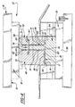
- a coining die apparatus used for reshaping the backing plates of rotary drum brake shoe cores in the production of remanufactured brake shoes is generally shown at 10 in the drawings.
- a typical metal brake core 11 to be reshaped by the apparatus 10 is shown best in Figure 2, and is of the usual type having an arcuate metal backing plate 12 having a convex outer surface 37 on which a friction liner (not shown) is bonded following the reshaping process, and an opposite concave inner surface 16 from which a pair of generally parallel, laterally spaced mounting brackets 14 extend for mounting the shoe in service on corresponding brake actuation system of a vehicle (not shown) such as a brake caliper device.
- the backing plate 12 includes side regions 70, 72 extending laterally from either side of the brackets 14 and a fairly narrow middle region 78 disposed in the space between the brackets 14.
- the backing plate 12 In service, the backing plate 12 is prone to warpage as illustrated in Figure 3, and thus part of the remanufacturing process involves reshaping the backing plate 12 to restore it to its original semi-circular shape to provide proper support to the friction liner that is subsequently applied.
- the present invention provides a way of reshaping the entire backing plate surface, including the middle and side regions 78. 70,72.
- the coining die apparatus 10 comprises a die set 18 including lower and upper dies generally indicated at 30 and 32 in the drawings supported for relative linear movement toward and away from one another between closed and opened positions.
- the lower die 30 is preferably stationary and mounted on a stationary base 20 of a press 24.
- the lower die 30 presents an upper concave working surface 35 having a size and shape complementing that of the convex outer surface 37 of the brake core 11, such that the brake core 11 can be supported on the lower die 30 with the convex outer surface 37 of the backing plate 12 nested and fully engaging the working surface 35 of the lower die 30 across the entire convex outer surface 37.
- the second or upper die 32 includes a pair of outer die portions or tools 48, 50 supported on a common head 19 for linear movement toward and away from the base 20.
- the head 19 may comprise an upper movable platen-32 of the die set 18 coupled to a suitable ram head 22, the upper movable platen 32 guided by telescoping platen sleeves 33 and the ram head 22 guided by telescoping press sleeves 35 during such linear movement.
- the ram head 22 may be driven by any type of linear actuation system, such as a hydraulic or pneumatic cylinder, mechanical linkage, or the like commonly used to operate the moving die of presses.
- the outer die portions 48, 50 are spaced laterally from one another by a distance sufficient to accommodate the mounting brackets 14 therebetween, as shown in Figures 1 and 3-5.
- the outer die portions 48. 50 have convex working surfaces 66, 68 facing the concave working surface 35 of the lower die 30.
- the convex working surfaces 66. 68 complement in size and shape the concave inner surface 16 of the backing plate 12 and, as illustrated best in Figures 3-5, engage the corresponding side regions 70. 72 of the backing plate 12 on the laterally opposite sides of the brackets 14 when the dies 32, 30 are forcibly closed to reshape such side regions 70, 72. restoring their original semi-circular shape.
- the apparatus thus far described is conventional and is typical of the type presently used to reshape brake core backing plates. It will be appreciated that the middle region 78 of the backing plate 12 is not acted upon by the outer die portions 48, 50, and thus the middle portion 78 is not reshaped by the outer die portions 48, 50 as are the side regions 70. 72 from being forcibly struck on opposite sides of the backing plate 12 by the opposing die working surfaces 35, 66. 68.
- the upper die 32 is further provided with a middle die portion or tool 74 disposed between the two outer die portions 48, 50 for engaging and reshaping the middle region 78 of the backing plate 12.
- the middle die portion 74 is supported on the head 19 and is movable therewith, but fixed relative to the adjacent outer die portions 48, 50.
- the middle die portion 74 is spaced laterally from each of the outer die portions 48, 50, providing corresponding gaps 86, 88 therebetween.
- the gaps 86, 88 are of sufficient width and depth to receive the mounting brackets 14 therein when the dies 32, 20 are closed.
- the middle die portion 74 has a convex working surface 80 sized and shaped to compliment a concave inner surface of the middle region 78 between the brackets 14.
- the middle die portion 74 extends between the brackets 14, bringing the working surface 80 into forcible contact with the backing plate 12 and thereby reshaping the middle region 78 simultaneously with the reshaping of the side regions 70, 72. In this way, it is assured that all regions of the backing plate 12, including the middle region 78, are reshaped by the operation.
- the lower and upper dies 30, 32 are mounted releasably to the base 20 and ram head 22, respectively, by a plurality of releasable pivot latches 26, 28, as shown best in FIGS. 1 and 5.
- the lower die 30 includes multiple parts, including a lower tool 34 removably attached to a flat rectangular base mounting plate 39.
- the lower tool 34 includes the upper concave working surface 35 and a plurality of bolt holes 36 which receive fastening bolts 44 for releasable attachment of the lower tool 34 to the base 20.
- the outer die portions or tools 48, 50 of the upper die 32 are releasably secured by fasteners to an intermediate mounting plate 52 which is in turn releasably secured by fasteners to the ram head 22.
- Spacers 82, 84 are disposed between the middle tool 74 and the outer tools 48, 50 to support the tools 82, 84, 74 in then laterally spaced relation and establish the gaps 86, 88 therebetween.
- the middle tool 74 and the spacers 82. 84 are secured in position between the outer tools 48, 50 by a pair of screws 90 shown best in FIGS. 2, 4 and 5.
- the screws 90 extend through axially aligned holes in the outer tool 50, the spacers 82, 84 and the middle tool 74 and are threaded into bores in the outer tool 48.
- the invention further contemplates the modification of an existing brake core coining apparatus by inclusion in the upper die of the middle die portion 74 between the two outer portions 48, 50 as described above.
- a spent brake shoe core 11 is stripped of its worn liner and loaded into the apparatus 10 with the outer surface of the backing plate 12 resting on the concave working surface 35 of the lower tool 34.
- the brake core backing plate 12 is then reshaped to correct any warpage or other shape defects by actuating the press 24 to cause the ram head 22 to force the upper die 32 downward toward the lower die 30.
- the downward motion of the upper die 32 causes the convex working surfaces 66, 80, 68 of the three upper (outer and middle) tools 48, 74, 50 to strike the concave inner surface 16 of the backing plate 12, sandwiching the backing plate 12 between the upper tools 48, 74, 50 and the lower tool 34.
- the axially-spaced side regions 70, 72 of the backing plate 12 are sandwiched between the lower tool 34 and the outer tools 48, 50, respectively.
- the middle region 78 of the backing plate 12 is sandwiched between the concave working surface 35 of the lower tool 34 and the working surface 80 of the middle tool 74.
- the coming process eliminates backing plate 12 warpage and returns the backing plate 12 to its original shape as shown in FIG. 4.
- a lining typically comprising asbestos and/or other suitable materials is bonded to the metal backing plate 12 to provide a surface suited to frictionally engage inner circumferential surfaces of a brake drum.
- middle tool 74 or "center punch'' provides an effective cost-efficient way of reshaping metal brake core backing plates for reuse. Required modifications to existing tool and die components are minimal and easily performed.
- the middle tool 74, along with the other tools described above. are releasably mounted in the press and thus are readily interchangeable with other tools configured to coin brake core backing plates having different mounting plate configurations and spacing.
Landscapes
- Engineering & Computer Science (AREA)
- Mechanical Engineering (AREA)
- General Engineering & Computer Science (AREA)
- Braking Arrangements (AREA)
Claims (9)
- Vorrichtung (10) zum Umformen verbrauchter Trommelbremskerne (11) bei der Herstellung wiederaufgearbeiteter Trommelbremsschuhe bzw. Trommelbremsbacken der Art, bei denen der Bremskern eine gekrümmte metallische Grundplatte (12) mit einer konvexen äußeren Oberfläche (37) einschließt, auf die ein Reibbelag aufgebracht bzw. geklebt werden soll, und eine konkave innere Oberfläche (16), von der sich ein Paar von seitlich beabstandeten Befestigungsklammern (14) erstreckt, die ein Paar von Seitenbereichen (70, 72) der Grundplatte definieren, die sich seitlich von den Halteklammern nach außen erstrecken, und ein Mittelbereich (78) der Grundplatte zwischen den Halteklammem angeordnet ist, wobei die Vorrichtung umfasst:ein Paar entgegengesetzter Umform-Pressformen bzw. -Gesenke (30, 32), die für die relative Bewegung zueinander und voneinander weg zwischen einer offenen und geschlossenen Position gehalten sind, wobei eines dieser Gesenke (30) eine konkave Arbeitsoberfläche (35) aufweist, die konfiguriert ist, die konvexe äußere Oberfläche einer Bremskemgrundplatte zu tragen bzw. zu halten, das andere der Gesenke (32) ein Paar von äußeren Gesenkabschnitten (48, 50) einschließt, die seitlich voneinander durch eine Entfernung beabstandet sind, die ausreichend ist, die Halteklammem des Bremskems dazwischen aufzunehmen, wenn die Gesenke in die geschlossene Position bewegt werden, wobei die äußeren Gesenkabschnitte (48, 50) konvexe Arbeitsoberflächen (66, 68) aufweisen, die konfiguriert sind, mit den entsprechenden Seitenbereichen der Grundplatte in Eingriff zu treten und diese umzuformen, wenn die Gesenke geschlossen sind, wobei die Vorrichtung weiter dadurch gekennzeichnet ist, dassdas andere der Gesenke (32) einen mittleren Gesenkabschnitt (74) einschließt, der zwischen, und seitlich beabstandet von jedem der äußeren Gesenkabschnitte angeordnet ist, um entsprechende Zwischenräume (86, 88) dazwischen von solcher Abmessung und Position bereitzustellen, um die Halteklammern darin, und den mittleren Abschnitt zwischen den Halteklammern unterzubringen, wenn die Gesenke geschlossen sind, wobei der mittlere Gesenkabschnitt eine konvexe Arbeitsoberfläche (80) aufweist, die konfiguriert ist, um mit dem entsprechenden Mittelbereich der Grundplatte in Eingriff zu treten und diesen umzuformen, wenn die Gesenke geschlossen sind.
- Vorrichtung gemäß Anspruch 1, dadurch gekennzeichnet, dass die äußeren und der mittlere Gesenkabschnitt (48, 50, 74) für eine verknüpfte Bewegung in Bezug aufeinander befestigt sind.
- Vorrichtung gemäß Anspruch 1 oder 2, dadurch gekennzeichnet, dass die Arbeitsoberflächen (66, 68, 80) der äußeren und des mittleren Gesenkabschnitts identische Profile aufweisen.
- Vorrichtung gemäß irgendeinem der Ansprüche 1 bis 3, dadurch gekennzeichnet, dass die Arbeitsoberflächen der Gesenkabschnitte allgemein halbkreisförmig sind.
- Vorrichtung gemäß irgendeinem der Ansprüche 1 bis 4, einschließend eine stationäre Basis, die das eine Gesenk (30) hält, und einen bewegbaren Kopf (22), der das andere Gesenk hält.
- Verfahren zum Umformen verbrauchter Trommelbremskerne (11) bei der Herstellung wiederaufgearbeiteter Trommelbremsschuhe der Art, bei denen der Bremskem eine gekrümmte metallische Grundplatte (12) mit einer konvexen äußeren Oberfläche (37) einschließt, auf die ein Reibbelag aufgebracht werden soll, und eine konkave innere Oberfläche (16), von der sich ein Paar von seitlich beabstandeten Befestigungsklammern (14) erstreckt, die ein Paar von Seitenbereichen (70, 72) der Grundplatte definieren, die sich seitlich von den Halteklammern nach außen erstrecken, und ein Mittelbereich (78) der Grundplatte zwischen den Halteklammnern angeordnet ist, wobei das Verfahren umfasst:Bereitstellen eines Paars entgegengesetzter Umformgesenke (30, 32), die für die relative Bewegung zueinander und voneinander weg zwischen einer offenen und geschlossenen Position gehalten sind;Bereitstellen eines dieser Gesenke (30) mit einer konkaven Arbeitsoberfläche (35), die konfiguriert ist, die konvexe äußere Oberfläche einer Bremskerngrundplatte zu halten;Bereitstellen des anderen der Gesenke (32) mit einem Paar von äußeren Gesenkabschnitten (48, 50), die seitlich voneinander durch eine Entfernung beabstandet sind, die ausreichend ist, die Halteklammern des Bremskerns dazwischen aufzunehmen, wenn die Gesenke in die geschlossene Position bewegt werden;Bereitstellen konvexer Arbeitsoberflächen (66, 68) auf den äußeren Gesenkabschnitten, die konfiguriert sind, mit den entsprechenden Seitenbereichen der Grundplatte in Eingriff zu treten und diese umzuformen, wenn die Gesenke geschlossen werden, wobei das Verfahren weiter gekennzeichnet ist durchBereitstellen eines mittleren Gesenkabschnitt (74) zwischen den zwei äußeren Gesenkabschnitten in seitlich von jedem der äußeren Gesenkabschnitte beabstandeter Weise, um entsprechende Zwischenräume (85, 88) dazwischen von solcher Abmessung und Position bereitzustellen, um die Halteklammern darin, und den mittleren Abschnitt (74) zwischen den Halteklammern unterzubringen, wenn die Gesenke geschlossen werden;Bereitstellen des mittleren Gesenkabschnitts mit einer konvexen Arbeitsoberfläche (80), die konfiguriert ist, um mit dem entsprechenden Mittelbereich der Grundplatte in Eingriff zu treten und diesen umzuformen, wenn die Gesenke geschlossen werden;Halten der konvexen äußeren Oberfläche (37) eines Bremskerns auf der konkaven Arbeitsoberfläche des einen Gesenks, undSchließen der Gesenke, um die äußeren Gesenkabschnitte (48, 50) und den mittleren Gesenkabschnitt (74) des anderen Gesenks in Zwangseingriff mit den jeweiligen Seitenabschnitten (70, 72) und dem Mittelbereich (78) der Grundplatte zu bringen, um die Platte umzuformen, wobei gleichzeitig die Halteklammern des Bremskerns in den Zwischenräumen zwischen den Gesenkabschnitten aufgenommen werden.
- Verfahren gemäß Anspruch 6, wobei die Arbeitsoberflächen (66, 68, 80) des äußeren und des mittleren Gesenkabschnitts mit einem allgemein halbkreisförmigen Profil bereitgestellt werden.
- Verfahren zum Modifizieren einer Bremskern-Präge- bzw. -Gesenkdrück-Vorrichtung (10) der Art, die beim Umformen verbrauchter Trommelbremskerne (11) bei der Herstellung wiederaufgearbeiteter Trommelbremsschuhe der Art verwendet wird, bei denen der Bremskern eine gekrümmte metallische Grundplatte (12) mit einer konvexen äußeren Oberfläche einschließt, mit der ein Reibbelag verbunden werden soll, und eine konkave innere Oberfläche (16), von der sich ein Paar von seitlich beabstandeten Befestigungsklammern (14) erstreckt, die ein Paar von Seitenbereichen der Grundplatte (70, 72) definieren, die sich seitlich von den Halteklammern nach außen erstrecken, und ein Mittelbereich der Grundplatte (78) zwischen den Halteklammern angeordnet ist, wobei die zu modifizierende Vorrichtung ein Paar entgegengesetzter Umformgesenke (30, 32) einschließt, die für die relative Bewegung zueinander und voneinander weg zwischen einer offenen und geschlossenen Position gehalten sind, wobei eines dieser Gesenke (30) eine konkave Arbeitsoberfläche (35) aufweist, die konfiguriert ist, die konvexe äußere Oberfläche einer Bremskerngrundplatte zu halten, das andere der Gesenke (32) ein Paar von äußeren Gesenkabschnitten (48, 50) einschließt, die seitlich voneinander durch eine Entfernung beabstandet sind, die ausreichend ist, die Halteklammern des Bremskerns dazwischen aufzunehmen, wenn die Gesenke in die geschlossene Position bewegt werden, wobei konvexe Arbeitsoberflächen (66, 68) auf den äußeren Gesenkabschnitten angeordnet sind, die konfiguriert sind, mit den entsprechenden Seitenbereichen der Grundplatte in Eingriff zu treten und diese umzuformen, wenn die Gesenke geschlossen werden, wobei das Verfahren weiter gekennzeichnet ist durch
Anordnen eines mittleren Gesenkabschnitts (74) zwischen den zwei äußeren Gesenkabschnitten, Beabstanden des mittleren Gesenkabschnitts seitlich von den benachbarten äußeren Gesenkabschnitten, um entsprechende Zwischenräume (86, 88) dazwischen von solcher Abmessung und Position bereitzustellen, um die Halteklammem darin, und den mittleren Abschnitt zwischen den Halteklammern unterzubringen, wenn die Gesenke geschlossen werden, und
Bereitstellen des mittleren Gesenkabschnitts mit einer konvexen Arbeitsoberfläche, die konfiguriert ist, um mit dem entsprechenden Mittelbereich der Grundplatte in Eingriff zu treten und diesen umzuformen, wenn die Gesenke geschlossen werden. - Verfahren gemäß Anspruch 8, worin die Arbeitsoberflächen (35, 66, 68, 80) der Gesenkabschnitte mit einem allgemein halbkreisförmigen Profil bereitgestellt werden.
Applications Claiming Priority (3)
| Application Number | Priority Date | Filing Date | Title |
|---|---|---|---|
| US364962 | 1982-04-02 | ||
| US09/364,962 US6250129B1 (en) | 1999-07-30 | 1999-07-30 | Apparatus and method for re-shaping brake cores |
| PCT/US2000/017720 WO2001008830A1 (en) | 1999-07-30 | 2000-06-28 | Apparatus and method for re-shaping brake cores |
Publications (3)
| Publication Number | Publication Date |
|---|---|
| EP1200212A1 EP1200212A1 (de) | 2002-05-02 |
| EP1200212A4 EP1200212A4 (de) | 2003-05-21 |
| EP1200212B1 true EP1200212B1 (de) | 2004-08-04 |
Family
ID=23436896
Family Applications (1)
| Application Number | Title | Priority Date | Filing Date |
|---|---|---|---|
| EP00943224A Expired - Lifetime EP1200212B1 (de) | 1999-07-30 | 2000-06-28 | Vorrichtung und verfahren zum umformen von bremmskernen |
Country Status (7)
| Country | Link |
|---|---|
| US (2) | US6250129B1 (de) |
| EP (1) | EP1200212B1 (de) |
| CA (1) | CA2379629C (de) |
| DE (1) | DE60012749T2 (de) |
| ES (1) | ES2223539T3 (de) |
| MX (1) | MXPA02001001A (de) |
| WO (1) | WO2001008830A1 (de) |
Families Citing this family (6)
| Publication number | Priority date | Publication date | Assignee | Title |
|---|---|---|---|---|
| US7353579B2 (en) * | 2005-01-28 | 2008-04-08 | Pratt & Whitney Canada Corp. | Flange restoring device and method |
| EP2380673A4 (de) * | 2008-11-25 | 2016-12-21 | Nippon Steel & Sumitomo Metal Corp | Vorrichtung zur korrektur der rohrendform eines uoe-metallrohrs |
| JP6202189B2 (ja) * | 2014-03-04 | 2017-09-27 | 新日鐵住金株式会社 | プレス成形品の製造方法、プレス成形品の製造装置、マンドレル |
| CN103978615B (zh) * | 2014-05-20 | 2017-02-01 | 莆田市金田摩配有限公司 | 一种刹车皮生产方法及成型设备 |
| CN109013758A (zh) * | 2018-08-21 | 2018-12-18 | 盐城加申汽车制动部件有限公司 | 一种刹车蹄片的校形装置 |
| CN117102285A (zh) * | 2023-07-30 | 2023-11-24 | 四川航天长征装备制造有限公司 | 一种航天用口盖类零件母线直线度手工快速校形工装及方法 |
Family Cites Families (24)
| Publication number | Priority date | Publication date | Assignee | Title |
|---|---|---|---|---|
| US35496A (en) * | 1862-06-03 | Improvement in apparatus for bending corrugated plates of metal | ||
| US493791A (en) | 1893-03-21 | Hermann sciiurig | ||
| US1879078A (en) * | 1930-04-04 | 1932-09-27 | Carlsen Carl | Method of and means for forming tubular articles |
| US2119900A (en) * | 1935-01-25 | 1938-06-07 | Glacier Co Ltd | Manufacture of bearings |
| US2646836A (en) * | 1950-04-19 | 1953-07-28 | Harry B Barrett | Brake lining clamp |
| US2814856A (en) * | 1954-01-19 | 1957-12-03 | Glacier Co Ltd | Method of manufacturing plain bearings and apparatus for making such bearings |
| US3055412A (en) * | 1954-07-22 | 1962-09-25 | Burndy Corp | Die assembly for crimping a shielded cable |
| US3101533A (en) | 1958-09-19 | 1963-08-27 | Eaton Mfg Co | Method of manufacturing brake shoes |
| US3842473A (en) * | 1971-12-22 | 1974-10-22 | Glacier Metal Co Ltd | Bearings |
| US4091652A (en) | 1977-01-28 | 1978-05-30 | Alumax, Inc. | Apparatus for shaping metal sheets |
| US4332998A (en) * | 1980-08-28 | 1982-06-01 | Rockwell International Corporation | Apparatus for welding automotive brake shoes |
| US4403494A (en) * | 1981-03-02 | 1983-09-13 | Arthur D. Little, Inc. | Method of fabricating scroll members by coining and tools therefor |
| US4453621A (en) * | 1982-06-07 | 1984-06-12 | General Motors Corporation | Drum brake shoe and lining assembly and method of making same |
| US4570475A (en) | 1984-06-01 | 1986-02-18 | Kerney Robert A | Brake shoe resizer |
| ES8604434A1 (es) * | 1984-07-13 | 1986-02-01 | Ormaechea Mujica Marcos | Procedimiento de fabricacion de zapatas para frenos |
| US4845817A (en) * | 1988-06-29 | 1989-07-11 | J. P. Industries, Inc. | Method of forming a half-round bearing |
| US4986101A (en) | 1990-05-25 | 1991-01-22 | Eaton Corporation | Process and apparatus for reforming brake shoes |
| US5168741A (en) * | 1990-11-20 | 1992-12-08 | Braunheim Stephen T | Method for forming a leading edge cover for jet engine blades |
| US5528001A (en) * | 1992-02-14 | 1996-06-18 | Research Organization For Circuit Knowledge | Circuit of electrically conductive paths on a dielectric with a grid of isolated conductive features that are electrically insulated from the paths |
| ATE143116T1 (de) * | 1992-03-30 | 1996-10-15 | Michael Robert Corbett | Herstellung von rohrverbindungen |
| US5607034A (en) * | 1995-03-08 | 1997-03-04 | Rockwell International Corporation | Cam brake shoe with formed edges |
| DE19540294C2 (de) * | 1995-10-28 | 1997-08-14 | Fichtel & Sachs Ag | Hydrodynamischer Drehmomentwandler mit Durchlaß im Gehäusedeckel |
| US5904123A (en) * | 1997-05-26 | 1999-05-18 | Ina Walzlager Schaeffler Ohg | Mechanical valve tappet |
| US6000270A (en) * | 1997-06-03 | 1999-12-14 | Sjm Engineering, Inc. | Collimator having tapered edges and method of making the same |
-
1999
- 1999-07-30 US US09/364,962 patent/US6250129B1/en not_active Expired - Fee Related
-
2000
- 2000-06-28 EP EP00943224A patent/EP1200212B1/de not_active Expired - Lifetime
- 2000-06-28 CA CA002379629A patent/CA2379629C/en not_active Expired - Fee Related
- 2000-06-28 DE DE60012749T patent/DE60012749T2/de not_active Expired - Fee Related
- 2000-06-28 MX MXPA02001001A patent/MXPA02001001A/es active IP Right Grant
- 2000-06-28 WO PCT/US2000/017720 patent/WO2001008830A1/en not_active Ceased
- 2000-06-28 ES ES00943224T patent/ES2223539T3/es not_active Expired - Lifetime
- 2000-08-07 US US09/633,432 patent/US6345427B1/en not_active Expired - Lifetime
Also Published As
| Publication number | Publication date |
|---|---|
| DE60012749T2 (de) | 2005-08-04 |
| US6345427B1 (en) | 2002-02-12 |
| EP1200212A1 (de) | 2002-05-02 |
| WO2001008830A1 (en) | 2001-02-08 |
| US6250129B1 (en) | 2001-06-26 |
| MXPA02001001A (es) | 2002-08-12 |
| CA2379629C (en) | 2006-08-01 |
| EP1200212A4 (de) | 2003-05-21 |
| ES2223539T3 (es) | 2005-03-01 |
| CA2379629A1 (en) | 2001-02-08 |
| DE60012749D1 (de) | 2004-09-09 |
Similar Documents
| Publication | Publication Date | Title |
|---|---|---|
| JP3578760B2 (ja) | 薄板金を液圧成形する装置および方法 | |
| US4627147A (en) | Method of constructing a refractory plate assembly for use in a sliding closure unit | |
| US6345427B1 (en) | Apparatus and method for re-shaping brake cores | |
| CA1190086A (en) | Mechanical and fluid actuated ram for powder compacting press and method of compacting powder material | |
| KR100400703B1 (ko) | 공구 복합 블럭을 갖는 다단 금속-성형 기계 | |
| SU1667988A1 (ru) | Штамп дл пробивки отверстий в полых издели х | |
| US4143569A (en) | Die holder for punch presses | |
| US4207048A (en) | Power presses and components for such presses | |
| CN211839710U (zh) | 螺母垫圈冲压装置 | |
| JP3709327B2 (ja) | 鍛造装置 | |
| KR20040102220A (ko) | 차량 드럼 브레이크 및 그 조립 방법 | |
| JP2007232064A (ja) | 有底円筒ピストンの防塵ブーツ用溝成形方法及び該成形方法によって作られるピストン | |
| JPH0739954A (ja) | しわ防止措置を施したプレス成形法としわ防止機構 | |
| WO1992018265A1 (en) | Riveting method and tool for carrying out said method | |
| JPH0232059B2 (de) | ||
| RU1795926C (ru) | Инструментальный блок дл штамповки тонкоплоскостных деталей | |
| SU1140856A1 (ru) | Способ сборки штампа совмещенного действи и устройство дл сборки штампа | |
| SU1741953A1 (ru) | Устройство дл креплени штампа на плите | |
| RU2243052C1 (ru) | Штамп | |
| JPH0137796Y2 (de) | ||
| RU1791057C (ru) | Штамп с эластичной средой | |
| CA1048402A (en) | Die holder for punch presses | |
| KR950005720B1 (ko) | 사출성형기의 금형 가압장치 | |
| CN120228171A (zh) | 一种可重复利用上下模座及压边圈的拉延模模具结构 | |
| RU1584221C (ru) | Штамп для листовой штамповки |
Legal Events
| Date | Code | Title | Description |
|---|---|---|---|
| PUAI | Public reference made under article 153(3) epc to a published international application that has entered the european phase |
Free format text: ORIGINAL CODE: 0009012 |
|
| 17P | Request for examination filed |
Effective date: 20020207 |
|
| AK | Designated contracting states |
Kind code of ref document: A1 Designated state(s): AT BE CH CY DE DK ES FI FR GB GR IE IT LI LU MC NL PT SE |
|
| RIN1 | Information on inventor provided before grant (corrected) |
Inventor name: BOSTIC, LAWRENCE, E. |
|
| RIC1 | Information provided on ipc code assigned before grant |
Ipc: 7B 23P 6/00 B Ipc: 7B 23P 11/00 B Ipc: 7B 23P 17/04 B Ipc: 7B 21D 31/00 A Ipc: 7B 21D 3/14 B Ipc: 7B 29C 73/00 B Ipc: 7B 21D 39/03 B Ipc: 7B 21D 17/02 B Ipc: 7B 23P 23/00 B Ipc: 7B 21D 53/34 B Ipc: 7B 21K 21/16 B |
|
| A4 | Supplementary search report drawn up and despatched |
Effective date: 20030403 |
|
| GRAP | Despatch of communication of intention to grant a patent |
Free format text: ORIGINAL CODE: EPIDOSNIGR1 |
|
| GRAS | Grant fee paid |
Free format text: ORIGINAL CODE: EPIDOSNIGR3 |
|
| GRAA | (expected) grant |
Free format text: ORIGINAL CODE: 0009210 |
|
| AK | Designated contracting states |
Kind code of ref document: B1 Designated state(s): DE ES FR GB IT |
|
| REG | Reference to a national code |
Ref country code: GB Ref legal event code: FG4D |
|
| REG | Reference to a national code |
Ref country code: IE Ref legal event code: FG4D |
|
| REF | Corresponds to: |
Ref document number: 60012749 Country of ref document: DE Date of ref document: 20040909 Kind code of ref document: P |
|
| REG | Reference to a national code |
Ref country code: ES Ref legal event code: FG2A Ref document number: 2223539 Country of ref document: ES Kind code of ref document: T3 |
|
| ET | Fr: translation filed | ||
| PLBE | No opposition filed within time limit |
Free format text: ORIGINAL CODE: 0009261 |
|
| STAA | Information on the status of an ep patent application or granted ep patent |
Free format text: STATUS: NO OPPOSITION FILED WITHIN TIME LIMIT |
|
| 26N | No opposition filed |
Effective date: 20050506 |
|
| PGFP | Annual fee paid to national office [announced via postgrant information from national office to epo] |
Ref country code: ES Payment date: 20070615 Year of fee payment: 8 |
|
| PGFP | Annual fee paid to national office [announced via postgrant information from national office to epo] |
Ref country code: DE Payment date: 20070629 Year of fee payment: 8 |
|
| PGFP | Annual fee paid to national office [announced via postgrant information from national office to epo] |
Ref country code: GB Payment date: 20070511 Year of fee payment: 8 |
|
| PGFP | Annual fee paid to national office [announced via postgrant information from national office to epo] |
Ref country code: IT Payment date: 20070620 Year of fee payment: 8 |
|
| PGFP | Annual fee paid to national office [announced via postgrant information from national office to epo] |
Ref country code: FR Payment date: 20070605 Year of fee payment: 8 |
|
| GBPC | Gb: european patent ceased through non-payment of renewal fee |
Effective date: 20080628 |
|
| REG | Reference to a national code |
Ref country code: FR Ref legal event code: ST Effective date: 20090228 |
|
| PG25 | Lapsed in a contracting state [announced via postgrant information from national office to epo] |
Ref country code: DE Free format text: LAPSE BECAUSE OF NON-PAYMENT OF DUE FEES Effective date: 20090101 |
|
| PG25 | Lapsed in a contracting state [announced via postgrant information from national office to epo] |
Ref country code: GB Free format text: LAPSE BECAUSE OF NON-PAYMENT OF DUE FEES Effective date: 20080628 |
|
| REG | Reference to a national code |
Ref country code: ES Ref legal event code: FD2A Effective date: 20080630 |
|
| PG25 | Lapsed in a contracting state [announced via postgrant information from national office to epo] |
Ref country code: IT Free format text: LAPSE BECAUSE OF NON-PAYMENT OF DUE FEES Effective date: 20080628 Ref country code: FR Free format text: LAPSE BECAUSE OF NON-PAYMENT OF DUE FEES Effective date: 20080630 |
|
| PG25 | Lapsed in a contracting state [announced via postgrant information from national office to epo] |
Ref country code: ES Free format text: LAPSE BECAUSE OF NON-PAYMENT OF DUE FEES Effective date: 20080630 |