EP1199809B1 - Procede et dispositif de detection de vitesse de codage - Google Patents
Procede et dispositif de detection de vitesse de codage Download PDFInfo
- Publication number
- EP1199809B1 EP1199809B1 EP00939176A EP00939176A EP1199809B1 EP 1199809 B1 EP1199809 B1 EP 1199809B1 EP 00939176 A EP00939176 A EP 00939176A EP 00939176 A EP00939176 A EP 00939176A EP 1199809 B1 EP1199809 B1 EP 1199809B1
- Authority
- EP
- European Patent Office
- Prior art keywords
- frequency
- signal
- synchronizing signal
- rate
- synchronization
- Prior art date
- Legal status (The legal status is an assumption and is not a legal conclusion. Google has not performed a legal analysis and makes no representation as to the accuracy of the status listed.)
- Expired - Lifetime
Links
Images


Classifications
-
- H—ELECTRICITY
- H03—ELECTRONIC CIRCUITRY
- H03M—CODING; DECODING; CODE CONVERSION IN GENERAL
- H03M13/00—Coding, decoding or code conversion, for error detection or error correction; Coding theory basic assumptions; Coding bounds; Error probability evaluation methods; Channel models; Simulation or testing of codes
- H03M13/33—Synchronisation based on error coding or decoding
-
- H—ELECTRICITY
- H03—ELECTRONIC CIRCUITRY
- H03M—CODING; DECODING; CODE CONVERSION IN GENERAL
- H03M13/00—Coding, decoding or code conversion, for error detection or error correction; Coding theory basic assumptions; Coding bounds; Error probability evaluation methods; Channel models; Simulation or testing of codes
- H03M13/01—Coding theory basic assumptions; Coding bounds; Error probability evaluation methods; Channel models; Simulation or testing of codes
-
- H—ELECTRICITY
- H04—ELECTRIC COMMUNICATION TECHNIQUE
- H04L—TRANSMISSION OF DIGITAL INFORMATION, e.g. TELEGRAPHIC COMMUNICATION
- H04L1/00—Arrangements for detecting or preventing errors in the information received
- H04L1/004—Arrangements for detecting or preventing errors in the information received by using forward error control
- H04L1/0045—Arrangements at the receiver end
- H04L1/0046—Code rate detection or code type detection
-
- H—ELECTRICITY
- H04—ELECTRIC COMMUNICATION TECHNIQUE
- H04L—TRANSMISSION OF DIGITAL INFORMATION, e.g. TELEGRAPHIC COMMUNICATION
- H04L7/00—Arrangements for synchronising receiver with transmitter
- H04L7/04—Speed or phase control by synchronisation signals
- H04L7/041—Speed or phase control by synchronisation signals using special codes as synchronising signal
Definitions
- the present invention relates to a rate detecting method and a rate detecting apparatus each for detecting, upon receipt of a signal coded at a predetermined rate, the rate of the coded signal that has been received.
- a Viterbi decoding method has been used as one of the convolutional decoding methods. If a coded signal is received and the rate r (m ⁇ r ⁇ n where m represents a minimum value and n represents a maximum value) of the received signal is unknown to the receiving side, the rate r has been detected conventionally by determining the synchronization of the coded signal by using a Viterbi decoder. In this case, it is sensed whether or not the synchronization can be determined by sequentially varying the frequency of a clock signal for determining the synchronization from the minimum value m of the coded signal to the maximum value n thereof in the receiving apparatus.
- the clock signal is reset to the frequency corresponding to the minimum value m of the rate and it is judged again whether or not the synchronization can be determined.
- the foregoing processes is repeatedly performed till the synchronization is determined.
- GB-A-2316585 describes a synchronization apparatus for adjusting a phase synchronization and a pattern synchronization provided by using a pres-stored code rate after pre-storing code rates synchronized for each channel in the vent of receiving the signal of the same channel;
- the method is provided for performing a fast and an effective synchronization by depuncturing the Viterbi-decoding transmitted convolutional codes punctured in a predetermined puncturing pattern assuming that a code rate is 5/6, comparing the calculated CBER (Channel Bit Error Rate) to a high/low threshold value, determining a code rate group to which the code rate of the codes belong, and performing a code rate detecting process, a phase synchronization and a pattern synchronization.
- CBER Channel Bit Error Rate
- the present invention reduces, when the synchronization of the coded signal that has been received is to be determined, the difference of the frequency corresponding to a rate for synchronization determination and the frequency corresponding to another different rate such that it is smaller than the difference of the frequency corresponding to the lower limit code rate and the frequency corresponding to the upper limit code rate of the coded signal that has been received.
- a rate detecting method assumes a rate detecting method for detecting, in a signal that has been coded at a predetermined rate, the predetermined rate of the coded signal, the method comprising: a first synchronizing signal generating step of generating a first synchronizing signal having a frequency corresponding to a first rate between lower and upper limit values of the rate; a first decoded signal generating step of decoding the coded signal based on the first synchronizing signal to generate a first decoded signal; a first synchronization determining step of determining whether or not desired synchronization is obtainable for the first decoded signal; a second synchronizing signal generating step of generating, if the synchronization of the coded signal is not obtainable in the first synchronization determining step, only a second synchronizing signal having a frequency corresponding to a second rate such that the difference of the frequency corresponding to the first rate and the frequency corresponding to the second rate is smaller than the difference of the frequency corresponding to
- the second synchronizing signal having the frequency corresponding to the second rate such that the difference of the frequency corresponding to the first rate and the frequency corresponding to the second rate is smaller than the difference of the frequency corresponding to the lower limit code rate and the frequency corresponding to the higher limit code rate is generated in the second synchronizing signal generating step. Accordingly, the difference between the frequency corresponding to the first synchronizing signal and the frequency corresponding to the second synchronizing signal is reduced to be smaller than the difference of the frequency corresponding to the lower limit code rate and the frequency corresponding to the higher limit code rate, which suppresses digital noise arising when switching is performed from the frequency of the first synchronizing signal to the frequency of the second synchronizing signal.
- the first decoded signal generating step or the second decoded signal generating step preferably includes the step of decoding the coded signal by using a Viterbi decoding method. This ensures decoding of the coded signal actually (commercially) used.
- the reiterating step preferably includes the step of changing the frequency of the second synchronizing signal such that is increases stepwise and if the frequency after the change is over the frequency corresponding to the upper limit code rate, changing the frequency of the second synchronizing signal such that it decreases stepwise. This allows the reiterating process to be performed positively without changing the frequency in a single step to the frequency corresponding to the lower limit code rate if the frequency after the change is over the frequency corresponding to the upper limit code rate.
- the reiterating step preferably includes the step of changing the frequency of the second synchronizing signal such that is decreases stepwise, and if the frequency after the change is under the frequency corresponding to the lower limit code rate, changing the frequency of the second synchronizing signal such that it increases stepwise.
- a rate detecting apparatus assumes a rate detecting apparatus for detecting, in a signal that has been coded at a predetermined rate, the predetermined rate of the coded signal, the apparatus comprising: a decoding circuit for receiving the coded signal and decoding the coded signal that has been received to output a decoded signal; a synchronizing signal generating circuit for generating a synchronizing signal used to perform synchronization determination with respect to the decoded signal and outputting the synchronizing signal to the decoding circuit; and a synchronization detecting circuit for receiving the decoded signal, performing predetermined synchronization determination with respect to the decoded signal that has been received, and outputting, if the synchronization has not been determined, a frequency switching signal for switching a frequency of the synchronization signal to the synchronizing signal generating circuit, the synchronizing signal generating circuit generating, based on the frequency switching signal, only a first synchronizing signal having a frequency corresponding to a first rate between lower and upper limit values of the
- the rate detecting apparatus of the present invention only the first synchronizing signal having the frequency corresponding to the first rate between the lower and upper limit values of the rate in the coded signal and the second synchronizing signal having the frequency corresponding to the second rate such that the difference of the frequency corresponding to the first rate and the frequency corresponding to the second rate is smaller than the difference of the frequency corresponding to the lower limit code rate and the frequency corresponding to the higher limit code rate are generated.
- the difference between the frequency corresponding to the first synchronizing signal's code rate and the frequency corresponding to the second synchronizing signal's code rate is smaller than the difference of the frequency corresponding to the lower limit code rate and the frequency corresponding to the higher limit code rate, which suppresses digital noise arising when switching is performed from the frequency of the first synchronizing signal to the frequency of the second synchronizing signal. Even if the apparatus according to the present invention has another circuit adjacent the peripheral portion thereof, the performance characteristics of the adjacent circuit are not affected thereby.
- the decoding circuit is preferably a Viterbi decoding circuit for performing decoding in accordance with a Viterbi decoding method. This ensures decoding of an actually used coded signal.
- the synchronizing signal generating circuit preferably changes the frequency of the second synchronizing signal such that it increases stepwise and changes, if the frequency after the change is over the frequency corresponding to the upper limit code rate, the frequency of the second synchronizing signal such that it decreases stepwise. This allows the reiterating process to be performed positively without changing the frequency in a single step to the frequency corresponding to the lower limit code rate if the frequency after the change is over the frequency corresponding to the upper limit code rate.
- the synchronizing signal generating circuit preferably changes the frequency of the second synchronizing signal such that it decreases stepwise and changes, if the frequency after the change is under the frequency corresponding to the lower limit code rate, the frequency of the second synchronizing signal such that it increases stepwise. This allows the reiterating process to be performed positively without changing the frequency in a single step to the frequency corresponding to the upper limit code rate if the frequency after the change is under the frequency corresponding to the lower limit code rate.
- FIG. 1 is a flow chart illustrating a rate detecting method according to the embodiment.
- the present invention assumes that, when a signal to be transmitted signal is coded in digital communication such as digital broadcasting, a specific one is not selected from a plurality of rates r prepared. Therefore, it is necessary for the receiving side to detect the rate at which the transmitted signal is coded and determine synchronization for the digital communication.
- synchronization determining methods there are a method of detecting a synchronization code and a method of using a path metric.
- a synchronization code having a given bit length e . g. , 8-bit "01000111" in the case of MPEG
- the method of using the path metric is a Viterbi decoding method.
- the path metric of the coded signal that has been received is observed and, if the value of the observed path metric is smaller than a predetermined threshold value, it is assumed that the synchronization has been determined.
- a clock signal as a synchronizing signal having a frequency corresponding to the minimum value r 1 of the rate is selected in an initial rate setting step ST10.
- a coded signal that has been received is decoded by using the selected clock signal.
- a first synchronization determining step ST12 synchronization determination is performed with respect to the decoded signal . If a path metric is smaller than a threshold value, it is judged that the synchronization has been determined, whereby the whole process is completed.
- a clock signal having a frequency corresponding to a rate r i+1 is selected in a first clock signal updating step ST13.
- the coded signal is decoded by using the selected clock signal in a second Viterbi Decoding Step ST15.
- a second synchronization determining step ST16 synchronization determination is performed with respect to the decoded signal and, if it is judged that the synchronization has been determined, the whole process is completed.
- a clock signal having a frequency corresponding to the rate r i-1 is selected in a second clock signal updating step SR17.
- the whole process returns to the second Viterbi decoding step ST15 where it is continued. If the rate r i is the minimum value r 1 thereof, the whole process returns to the first Viterbi decoding step ST11 where it is continued. The foregoing process is repeatedly performed till the result of the synchronization determination is judged to be true.
- synchronization determination is performed by switching between the corresponding frequencies of the clock signals in such a manner as to reciprocate between the minimum and maximum values r 1 and r k of the rate. Since only the clock signals having variations smaller than the difference of the frequencies corresponding to the minimum and maximum values r 1 and r k respectively are generated without jumping in a single step from the minimum value generating corresponding to the minimum value r 1 of the rate to the maximum value generating frequency corresponding to the maximum value r k thereof skipping the in-between frequencies, digital noise arising in switching the frequency of the clock signal can be suppressed significantly.
- the present embodiment has used the Viterbi decoding method as a decoding process, another decoding method compatible with the method in which the signal has been coded may be used appropriately.
- FIG. 2 shows a functional structure of the rate detecting apparatus according to the present embodiment .
- a rate detecting apparatus 30 comprises: a clock generating circuit 31 as a circuit for generating and outputting a clock signal 21 as a synchronizing signal; a Viterbi decoding circuit 32 for performing Viterbi decoding with respect to a coded signal 22 inputted thereto based on the clock signal 21 and outputting a decoded signal 23 ; and a synchronization detecting circuit 33 for receiving the decoded signal 23 , performing synchronization determination with respect to the received decoded signal 23 by observing a path metric, and outputting a clock switching signal 24 as a frequency switching signal for switching the frequency of the clock signal 21 to the clock generating circuit 31 if the synchronization has not been determined.
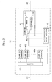
- FIG. 3 shows a functional structure of the clock generating circuit 31 according to the present embodiment.
- the clock generating circuit 31 is composed of: a counter 41 for increasing or decreasing the rate r i based on the clock switching signal 24 ; a maximum/minimum values detector 42 for sensing whether or not the frequency of a signal outputted from the counter 41 is the maximum (upper limit) value or the minimum (lower limit) value of the counter; a plurality of clock generators 431 to 43k for generating and outputting frequencies different from each other; and a selector 44 for selecting among respective output signals from the plurality of clock generators 431 to 43k based on an output signal from the counter 41.
- the counter 41 has: an adder 411 for adding 1 to the value of i of the rate r i to be detected every time the clock switching signal 24 is inputted thereto; a subtracter 412 for subtracting 1 from the value of i of the rate r i every time the clock switching signal 24 is inputted thereto; and a switch 413 for switching between the respective output signals from the adder 411 and the subtracter 412,
- the rate r i of the coded signal 22 that has been received is determined at the k stages of r 1 ⁇ r i ⁇ r k . Accordingly, the clock generators 431 to 43k in the clock generating circuit 31 generate the frequencies (f 1 ⁇ f i ⁇ f k ) of the clock signal 21 which correspond to the rates r i .
- the initial value is assumed to be 1 in the counter 41 of the clock generating circuit 31 and the switch 413 is connected to the adder 411 .
- the selector 44 selects the clock signal from the clock generator 431 based on an instruction given by the counter 41.
- the decoding circuit 32 performs Viterbi decoding with respect to the coded signal 22 that has been received based on the clock signal 21 inputted thereto and outputs the decoded signal 23 to the synchronization detecting circuit 33.
- the synchronization detecting circuit 33 Upon receipt of the decoded signal 23, the synchronization detecting circuit 33 performs predetermined synchronization determination and outputs, if synchronization can not be determined, the clock switching signal 24 for switching the frequency of the clock signal 21 to the clock generating circuit 31.
- the counter 41 that has received the clock switching signal 24 adds only one to the value in the adder 411. Then, if the value of i of the rate r i reaches k as the maximum value, the maximum/minimum values detector 42 switches the connection of the switch 413 to an output terminal of the subtracter 412 . If the value of the i of the rate r i reaches 1 as the minimum value, the switch 413 is connected to output terminal of the adder 411.
- the k clock generators 431 to 43k Since the clock signal 21 is switched only between the frequencies adjacent to each other, the k clock generators 431 to 43k generate only the clock signals having variations smaller than the difference of the frequencies corresponding to the minimum and maximum values r 1 and r k respectively without jumping in a single step from the frequency generated by the clock generator 431 corresponding to the minimum value r 1 of the rate to the frequency generated by the clock generator 43k corresponding to the maximum value r k of the rate and skipping the in-between values. This significantly suppresses the digital noise arising when the frequency of the clock signal is switched so that, even if the rate detecting circuit according to the present embodiment and an analog circuit are mixedly integrated, the performance characteristics of the analog circuit are no more affected thereby.
- the Ivterbi decoding circuit 32 has been used as a decoding circuit, a decoding circuit compatible with the method in which the signal has been coded my be used appropriately.
- synchronization determination can be performed starting from the maximum value r k of the rate which decreases stepwise.
Landscapes
- Engineering & Computer Science (AREA)
- Physics & Mathematics (AREA)
- Probability & Statistics with Applications (AREA)
- Theoretical Computer Science (AREA)
- Computer Networks & Wireless Communication (AREA)
- Signal Processing (AREA)
- Error Detection And Correction (AREA)
- Synchronisation In Digital Transmission Systems (AREA)
- Compression Or Coding Systems Of Tv Signals (AREA)
Claims (8)
- Procédé de détection de taux de codage pour détecter le taux prédéterminé d'un signal codé dans un système de communication numérique comprenant :une première étape de génération de signal de synchronisation consistant à générer un premier signal de synchronisation présentant une fréquence correspondant à un premier taux qui se situe entre un taux de code de limite inférieure présentant une fréquence basse correspondante et un taux de code de limite supérieure présentant une fréquence haute correspondante ;une première étape de génération de signal décodé consistant à décoder le signal codé sur la base du premier signal de synchronisation pour générer un premier signal décodé ;une première étape de détermination de synchronisation consistant à déterminer si oui ou non la synchronisation désirée peut être obtenue pour le premier signal décodé ;une seconde étape de génération de signal de synchronisation consistant à générer, si la synchronisation du signal codé ne peut pas être obtenue dans la première étape de détermination de synchronisation, un second signal de synchronisation présentant une fréquence correspondant à un second taux de sorte que la différence de fréquence correspondant au premier taux et de la fréquence correspondant au second taux est plus petite que la différence de la fréquence correspondant au taux de code de limite inférieure et à la fréquence correspondant au taux de code de limite supérieure ;une seconde étape de génération de signal décodé consistant à décoder le signal codé sur la base du second signal de synchronisation pour générer un second signal décodé ;une seconde étape de détermination de synchronisation consistant à déterminer si oui ou non la synchronisation désirée peut être obtenue pour le second signal décodé ; etune étape de réitération consistant à réitérer, si la synchronisation du signal codé ne peut pas être obtenue dans la seconde étape de synchronisation, la seconde étape de génération du signal décodé et la seconde étape de détermination de synchronisation jusqu'à ce que la synchronisation du signal codé soit obtenue, tout en changeant la fréquence du second signal de synchronisation de sorte que la différence de la fréquence correspondant à ce nouveau signal de synchronisation et de la fréquence correspondant au dernier signal de synchronisation est plus petite que la différence de la fréquence correspondant au taux de code de limite inférieure et de la fréquence correspondant au taux de code de limite supérieure.
- Procédé selon la revendication 1, dans lequel la première étape de génération de signal décodé ou la seconde étape de génération de signal décodé inclut l'étape consistant à décoder le signal codé en utilisant un procédé de décodage Viterbi.
- Procédé selon la revendication 1 ou 2, dans lequel l'étape de réitération inclut l'étape consistant à changer la fréquence du second signal de synchronisation de sorte qu'elle augmente par pas et si la fréquence après le changement est au-dessus de la fréquence correspondant au taux de code de limite supérieure, changer la fréquence du second signal de synchronisation de sorte qu'elle diminue par pas.
- Procédé selon la revendication 1 ou 2 dans lequel l'étape de réitération inclut l'étape consistant à changer la fréquence du second signal de synchronisation de sorte qu'elle diminue par pas et si la fréquence après le changement est en dessous de la fréquence correspondant au taux de code de limite inférieure, changer la fréquence du second signal de synchronisation de sorte qu'elle augmente par pas.
- Appareil de détection de taux de code (30) pour détecter le taux prédéterminé d'un signal codé ( 22) dans un système de communication numérique comprenant :un circuit de décodage (32) pour recevoir le signal codé (22) et pour décoder le signal codé (22) qui a été reçu pour sortir un signal décodé (23)un circuit de génération de signal de synchronisation (31) pour générer un signal de synchronisation (21) utilisé pour effectuer la détermination de la synchronisation par rapport au signal décodé et pour sortir le signal de synchronisation (21) vers le circuit de décodage (32) ; etun circuit de détection de synchronisation (33) pour recevoir le signal décodé (23), effectuant la détermination de synchronisation prédéterminée par rapport au signal décodé (23) qui a été reçu et sortir, si la synchronisation n'a pas été déterminée, un signal de commutation de fréquence (24) pour commuter une fréquence du signal de synchronisation (21) vers le circuit de génération du signal de synchronisation (21),le circuit de génération de signal de synchronisation générant, sur la base du signal de commutation de fréquence (24), un nouveau signal de synchronisation présentant une fréquence correspondant à un taux de code différent de sorte que la différence de la fréquence correspondant au nouveau signal de synchronisation et de la fréquence correspondant au dernier signal de synchronisation est plus petite que la différence de la fréquence correspondant au taux de code de limite inférieure et de la fréquence correspondant au taux de code de limite supérieure.
- Appareil selon la revendication 5, dans lequel le circuit de décodage (32) est un circuit de décodage Viterbi pour effectuer le décodage en conformité avec un procédé de décodage Viterbi.
- Appareil selon la revendication 5 ou 6, dans lequel le circuit de génération de signal de synchronisation (31) change la fréquence du second signal de synchronisation de sorte qu'elle augmente par pas et change, si la fréquence après le changement est au-dessous de la fréquence correspondant au taux de code de limite supérieure, la fréquence du second signal de synchronisation de sorte qu'elle diminue par pas.
- Appareil selon la revendication 5 ou 6, dans lequel le circuit de génération de signal de synchronisation (31) change la fréquence du second signal de synchronisation de sorte qu'elle diminue par pas et change, si la fréquence après le changement est au-dessous de la fréquence correspondant au taux de code de limite inférieure, la fréquence du second signal de synchronisation de sorte qu'elle augmente par pas.
Applications Claiming Priority (3)
| Application Number | Priority Date | Filing Date | Title |
|---|---|---|---|
| JP18282999A JP3340403B2 (ja) | 1999-06-29 | 1999-06-29 | 符号化率検出方法及び符号化率検出装置 |
| JP18282999 | 1999-06-29 | ||
| PCT/JP2000/004220 WO2001001580A1 (fr) | 1999-06-29 | 2000-06-27 | Procede et dispositif de detection de vitesse de codage |
Publications (3)
| Publication Number | Publication Date |
|---|---|
| EP1199809A1 EP1199809A1 (fr) | 2002-04-24 |
| EP1199809A4 EP1199809A4 (fr) | 2002-10-09 |
| EP1199809B1 true EP1199809B1 (fr) | 2004-01-07 |
Family
ID=16125204
Family Applications (1)
| Application Number | Title | Priority Date | Filing Date |
|---|---|---|---|
| EP00939176A Expired - Lifetime EP1199809B1 (fr) | 1999-06-29 | 2000-06-27 | Procede et dispositif de detection de vitesse de codage |
Country Status (8)
| Country | Link |
|---|---|
| US (1) | US6728926B1 (fr) |
| EP (1) | EP1199809B1 (fr) |
| JP (1) | JP3340403B2 (fr) |
| KR (1) | KR100626922B1 (fr) |
| CN (1) | CN1159853C (fr) |
| DE (1) | DE60007639T2 (fr) |
| TW (1) | TW463467B (fr) |
| WO (1) | WO2001001580A1 (fr) |
Families Citing this family (2)
| Publication number | Priority date | Publication date | Assignee | Title |
|---|---|---|---|---|
| JP2002108490A (ja) * | 2000-07-26 | 2002-04-10 | Sony Corp | クロック供給回路 |
| KR100830588B1 (ko) * | 2007-02-28 | 2008-05-22 | 삼성전자주식회사 | 데이터 율에 따라 클록의 주파수가 스케일링되는 초광대역수신기 및 수신 방법 |
Family Cites Families (14)
| Publication number | Priority date | Publication date | Assignee | Title |
|---|---|---|---|---|
| US4578800A (en) | 1982-07-12 | 1986-03-25 | Yutaka Yasuda | Synchronization circuit for a Viterbi decoder |
| US4802174A (en) | 1986-02-19 | 1989-01-31 | Sony Corporation | Viterbi decoder with detection of synchronous or asynchronous states |
| JP2786342B2 (ja) | 1991-05-10 | 1998-08-13 | 三菱電機株式会社 | ビタビ復号器 |
| JP2522142B2 (ja) | 1992-12-25 | 1996-08-07 | 日本電気株式会社 | ビタビ復号器の同期検出方式 |
| JP3123289B2 (ja) | 1993-03-04 | 2001-01-09 | ソニー株式会社 | ビタビ復号装置 |
| US5563912A (en) * | 1995-02-27 | 1996-10-08 | Nec Corporation | High efficiency speech coding apparatus and transit switching system employing the same |
| US5859861A (en) * | 1995-06-21 | 1999-01-12 | Hyundai Electronics Ind. Co., Ltd. | High speed viterbi decoder |
| JPH0951278A (ja) | 1995-08-08 | 1997-02-18 | Toshiba Corp | ビタビ復号器 |
| JPH09135177A (ja) | 1995-11-07 | 1997-05-20 | Toshiba Corp | ビタビ復号同期判定方法および装置 |
| US5978414A (en) * | 1996-07-03 | 1999-11-02 | Matsushita Electric Industrial Co., Ltd. | Transmission rate judging unit |
| GB2316585A (en) | 1996-08-23 | 1998-02-25 | Daewoo Electronics Co Ltd | Synchronization method and apparatus in Viterbi decoder |
| JP3201962B2 (ja) | 1996-11-11 | 2001-08-27 | 株式会社ワイ・アール・ピー移動通信基盤技術研究所 | 可変データレート通信装置 |
| US6463097B1 (en) * | 1998-10-16 | 2002-10-08 | Koninklijke Philips Electronics N.V. | Rate detection in direct sequence code division multiple access systems |
| US6567466B1 (en) * | 1999-02-16 | 2003-05-20 | Agere Systems Inc. | Method and apparatus for determining the data rate of a received signal in a variable data rate orthogonal spread spectrum communication system |
-
1999
- 1999-06-29 JP JP18282999A patent/JP3340403B2/ja not_active Expired - Fee Related
-
2000
- 2000-06-27 DE DE2000607639 patent/DE60007639T2/de not_active Expired - Lifetime
- 2000-06-27 WO PCT/JP2000/004220 patent/WO2001001580A1/fr active IP Right Grant
- 2000-06-27 TW TW89112680A patent/TW463467B/zh not_active IP Right Cessation
- 2000-06-27 CN CNB008043663A patent/CN1159853C/zh not_active Expired - Fee Related
- 2000-06-27 KR KR1020017004558A patent/KR100626922B1/ko not_active IP Right Cessation
- 2000-06-27 US US09/831,636 patent/US6728926B1/en not_active Expired - Fee Related
- 2000-06-27 EP EP00939176A patent/EP1199809B1/fr not_active Expired - Lifetime
Also Published As
| Publication number | Publication date |
|---|---|
| CN1342345A (zh) | 2002-03-27 |
| KR20020013826A (ko) | 2002-02-21 |
| DE60007639D1 (de) | 2004-02-12 |
| EP1199809A1 (fr) | 2002-04-24 |
| EP1199809A4 (fr) | 2002-10-09 |
| CN1159853C (zh) | 2004-07-28 |
| TW463467B (en) | 2001-11-11 |
| WO2001001580A1 (fr) | 2001-01-04 |
| JP2001016114A (ja) | 2001-01-19 |
| US6728926B1 (en) | 2004-04-27 |
| KR100626922B1 (ko) | 2006-09-20 |
| JP3340403B2 (ja) | 2002-11-05 |
| DE60007639T2 (de) | 2004-06-17 |
Similar Documents
| Publication | Publication Date | Title |
|---|---|---|
| JPH1051780A (ja) | トレリス符号化されたビデオ・データを処理するためのシステムおよび方法 | |
| WO2002049303A1 (fr) | Recepteur | |
| JP3923743B2 (ja) | 復号装置及び復号方法 | |
| KR20010033503A (ko) | 버터플라이 동작을 이용한 비-이진 비터비 디코더 | |
| JPH11340840A (ja) | 移動通信端末及び送信ビットレート判別方法 | |
| EP1199809B1 (fr) | Procede et dispositif de detection de vitesse de codage | |
| US6310887B1 (en) | Transmission speed predicting apparatus and transmission speed predicting method | |
| JPH06276107A (ja) | ビタビ復号器の同期検出方式 | |
| US6084925A (en) | Method and apparatus for discriminating synchronous or asynchronous states of Viterbi decoded data | |
| US6637003B1 (en) | Viterbi decoder and synchronism controlling method | |
| KR100249046B1 (ko) | 격자복호기의 역추적장치 | |
| US6915479B2 (en) | Apparatus and method for error correction | |
| KR100431162B1 (ko) | 코드레이트 검출장치 | |
| JPH0918466A (ja) | フレーム同期方式 | |
| JPH10150439A (ja) | フレーム同期回路および通信システム | |
| JP3259339B2 (ja) | ビタビ復号方法およびその装置 | |
| JPH09135177A (ja) | ビタビ復号同期判定方法および装置 | |
| JPH1093648A (ja) | Qpsk復調器 | |
| KR100396756B1 (ko) | 비터비 복호기 | |
| JPH0677941A (ja) | ダイバーシチ無線送受信方式 | |
| KR100488136B1 (ko) | 고정길이결정창을이용한데이터신호디코딩방법 | |
| JP2752859B2 (ja) | 誤り訂正方式及びこれに用いるハーゲルバーガー復号回路 | |
| JPH038142B2 (fr) | ||
| JPH1131979A (ja) | ビタビ復号方法及びビタビ復号回路 | |
| JPH11220431A (ja) | 最適受信周波数選択方法 |
Legal Events
| Date | Code | Title | Description |
|---|---|---|---|
| PUAI | Public reference made under article 153(3) epc to a published international application that has entered the european phase |
Free format text: ORIGINAL CODE: 0009012 |
|
| 17P | Request for examination filed |
Effective date: 20020117 |
|
| AK | Designated contracting states |
Kind code of ref document: A1 Designated state(s): AT BE CH CY DE DK ES FI FR GB GR IE IT LI LU MC NL PT SE |
|
| A4 | Supplementary search report drawn up and despatched |
Effective date: 20020822 |
|
| AK | Designated contracting states |
Kind code of ref document: A4 Designated state(s): AT BE CH CY DE DK ES FI FR GB GR IE IT LI LU MC NL PT SE |
|
| RIC1 | Information provided on ipc code assigned before grant |
Free format text: 7H 04L 1/00 A |
|
| 17Q | First examination report despatched |
Effective date: 20021107 |
|
| GRAP | Despatch of communication of intention to grant a patent |
Free format text: ORIGINAL CODE: EPIDOSNIGR1 |
|
| GRAS | Grant fee paid |
Free format text: ORIGINAL CODE: EPIDOSNIGR3 |
|
| GRAA | (expected) grant |
Free format text: ORIGINAL CODE: 0009210 |
|
| AK | Designated contracting states |
Kind code of ref document: B1 Designated state(s): DE FR GB |
|
| REG | Reference to a national code |
Ref country code: GB Ref legal event code: FG4D |
|
| REG | Reference to a national code |
Ref country code: IE Ref legal event code: FG4D |
|
| REF | Corresponds to: |
Ref document number: 60007639 Country of ref document: DE Date of ref document: 20040212 Kind code of ref document: P |
|
| ET | Fr: translation filed | ||
| PLBE | No opposition filed within time limit |
Free format text: ORIGINAL CODE: 0009261 |
|
| STAA | Information on the status of an ep patent application or granted ep patent |
Free format text: STATUS: NO OPPOSITION FILED WITHIN TIME LIMIT |
|
| 26N | No opposition filed |
Effective date: 20041008 |
|
| REG | Reference to a national code |
Ref country code: IE Ref legal event code: MM4A |
|
| PGFP | Annual fee paid to national office [announced via postgrant information from national office to epo] |
Ref country code: FR Payment date: 20100709 Year of fee payment: 11 |
|
| PGFP | Annual fee paid to national office [announced via postgrant information from national office to epo] |
Ref country code: GB Payment date: 20100623 Year of fee payment: 11 Ref country code: DE Payment date: 20100625 Year of fee payment: 11 |
|
| GBPC | Gb: european patent ceased through non-payment of renewal fee |
Effective date: 20110627 |
|
| REG | Reference to a national code |
Ref country code: FR Ref legal event code: ST Effective date: 20120229 |
|
| REG | Reference to a national code |
Ref country code: DE Ref legal event code: R119 Ref document number: 60007639 Country of ref document: DE Effective date: 20120103 |
|
| PG25 | Lapsed in a contracting state [announced via postgrant information from national office to epo] |
Ref country code: FR Free format text: LAPSE BECAUSE OF NON-PAYMENT OF DUE FEES Effective date: 20110630 Ref country code: DE Free format text: LAPSE BECAUSE OF NON-PAYMENT OF DUE FEES Effective date: 20120103 |
|
| PG25 | Lapsed in a contracting state [announced via postgrant information from national office to epo] |
Ref country code: GB Free format text: LAPSE BECAUSE OF NON-PAYMENT OF DUE FEES Effective date: 20110627 |