EP1198694B1 - Optischer sensor zur messung des abstands und der neigung einer fläche - Google Patents
Optischer sensor zur messung des abstands und der neigung einer fläche Download PDFInfo
- Publication number
- EP1198694B1 EP1198694B1 EP01945110A EP01945110A EP1198694B1 EP 1198694 B1 EP1198694 B1 EP 1198694B1 EP 01945110 A EP01945110 A EP 01945110A EP 01945110 A EP01945110 A EP 01945110A EP 1198694 B1 EP1198694 B1 EP 1198694B1
- Authority
- EP
- European Patent Office
- Prior art keywords
- detector
- plane
- inclination
- distance
- substrate
- Prior art date
- Legal status (The legal status is an assumption and is not a legal conclusion. Google has not performed a legal analysis and makes no representation as to the accuracy of the status listed.)
- Expired - Lifetime
Links
Images




Classifications
-
- G—PHYSICS
- G01—MEASURING; TESTING
- G01B—MEASURING LENGTH, THICKNESS OR SIMILAR LINEAR DIMENSIONS; MEASURING ANGLES; MEASURING AREAS; MEASURING IRREGULARITIES OF SURFACES OR CONTOURS
- G01B11/00—Measuring arrangements characterised by the use of optical techniques
- G01B11/24—Measuring arrangements characterised by the use of optical techniques for measuring contours or curvatures
-
- G—PHYSICS
- G01—MEASURING; TESTING
- G01B—MEASURING LENGTH, THICKNESS OR SIMILAR LINEAR DIMENSIONS; MEASURING ANGLES; MEASURING AREAS; MEASURING IRREGULARITIES OF SURFACES OR CONTOURS
- G01B11/00—Measuring arrangements characterised by the use of optical techniques
- G01B11/02—Measuring arrangements characterised by the use of optical techniques for measuring length, width or thickness
- G01B11/026—Measuring arrangements characterised by the use of optical techniques for measuring length, width or thickness by measuring distance between sensor and object
Definitions
- WO88 / 07657 describes a distance meter or profile knife with a linear illumination of a surface.
- JP01035305 A the reflections of two lines of light on two crossed detectors are evaluated for distance measurement.
- the plane to be observed must also be oriented with respect to its inclination so that the entire object plane is sharply imaged.
- the inclination must be aligned with respect to the optical axis of the objective used for observation when the lens detects the entire observed area, or with respect to the plane in which the sample is moved when the surface is scanned to detect them in their entirety.
- the invention is a glass substrate on which molecules are bound, which is to be focused for the observation of the fluorescence of these molecules with respect to a lens. Since the field of view of the objective is very large and the depth of field very small, the substrate must be aligned with respect to the optical axis of the objective, so that the entire surface occupied with molecules can be detected in the same quality. The observation of the fluorescence is carried out through the substrate, so that not the front of the substrate must be focused and aligned but occupied with molecules back.
- the invention is therefore based on the object to determine the inclination and the distance of the back of a glass substrate to a reference plane.
- the senor must detect three coordinates: the focusing, that is, the vertical distance of the substrate to the reference plane (nominal object plane) at a certain point and the inclination about two orthogonal axes lying in the reference plane.
- the three detected coordinates must not influence each other. That is, an inclination of the substrate with respect to one of the two axes must not affect the measurement of the inclination with respect to the other axis nor the measurement of the distance. At a minimum, the interference must be sufficiently small and disappear near the optimum orientation and focus of the substrate.
- This condition results from the goal of aligning the sample based on the measurement result of the sensor. If the deposition from the desired position in one coordinate influences the measurement results of the other coordinates too much, a converging algorithm for aligning the sample can not be specified.
- a further difficulty with substrates with wedge defects and not exactly defined thickness is to separate the beams reflected from the front and back of the substrate to specifically determine the tilt and focus of a page.
- a clean separation is unavoidable in particular if the considered interface has a lower reflectivity. This case is exemplified when the inner surface of a cuvette filled with aqueous solution is to be aligned. Due to the lower refractive index jump between the liquid and the glass compared to the refractive index jump between air and glass, the reflection on the inner surface is much smaller than the reflection on the outside.
- the inclination is detected by means of a collimated laser beam.
- the beam is reflected at the interfaces of the substrate and the deviation of the reflected beam from its defined by the desired position direction determined.
- the distance is determined on the basis of the triangulation principle.
- a slender light beam for example a laser beam, directed.
- the observation is from a different direction than the illumination. Ideally, it is observed from the direction in which the illumination beam is reflected. For non-scattering samples this is the requirement for light to be observed at all.
- the light spot (12) on the sample is imaged by optics onto a location sensitive detector (e.g., a CCD array). As the sample is moved toward the normal of the substrate, the image of the spot (12) s on the detector moves away from its location defined by the desired location. The distance from the desired position is a measure of the shift in the direction of the surface normal.
- the invention advantageously combines a tilt sensor and a triangulation sensor in a single beam path.
- the reflected rays must be separated from the front and back of the substrate.
- an anamorphic optics which meridionally focuses the laser beam onto the surface to be measured, while the beam is collimated sagittally.
- the meridional plane is the plane in which the beam path of the sensor is located and which is perpendicular to the reference plane.
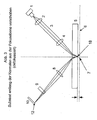
- FIGs 1a, 1b and 1c an embodiment of the beam path according to the invention is shown.
- the drawing level is from Fig. 1a the meridional plane and in Fig. 1b a projection of the beam path according to the invention is shown on the reference plane.
- an image of the survey point (18) in the reference plane (6) in which distance and tilt are to be determined is made on the location sensitive detector (10) (e.g., CCD array).
- This image serves according to the triangulation principle for determining the distance of the surface or interface of the substrate (5) to be measured from the reference plane (6) in the measurement point (18).
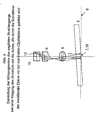
- the beam reflected at the unobserved interface (front) is not imaged onto the detector (10), since this interface is outside the field of view of the detector (10) (capture area of the proximity sensor). Thus, it no longer superimposes the beam reflected at the considered boundary surface and thus does not disturb either the distance measurement or the determination of the inclination of this interface.
- Figure 3 the substrate is shown displaced from its nominal position in the direction of the normal on the reference plane (6).
- the drawing plane is like in Fig. 1 a the meridional plane.
- the line focus (7) is shifted with respect to the survey point (18) and is no longer imaged by the lens (8) on the location defined by the desired position on the detector.
- the position of the light spot (12) generated on the position-sensitive detector (10) thus reflects the distance of the substrate perpendicular to the reference plane in the measuring point (18).
- Figure 4 is the inclination of the substrate about an axis (A2) perpendicular to the plane of the drawing which passes through the survey point (18).
- the drawing plane of Fig. 4 is the meridional plane of the ray path. Since the line focus (7) is not offset by the inclination of the substrate with respect to the Verressstician (18), the light spot (12) on the detector (10) is in its desired position.
- FIG. 5 a projection of the observation beam is shown on a plane perpendicular to the axis of rotation (A1).
- the beam path according to the invention in addition to the distance of the back of the substrate from the survey point (18) and the inclination of the substrate to those in the meridionalen plane (drawing plane of Fig. 1a . 2 . 3 . 4 ) and the reference plane (6) lying axis of rotation (A1) measure.
- the sagittally collimated beam reflected from the substrate backside is focused sagittally on the detector (10) by the observation optics (lenses 8 and 9).
- the position of the light spot (12) on the detector thus reflects the beam direction in the sagittal plane, and thus the inclination of the substrate with respect to the axis of rotation (A1) which is defined by the meridional plane of intersection (plane of Fig. 1a . 2 . 3 . 4 ) and the reference plane (6 in Fig. 1a, drawing plane of Fig. 1b ) is formed.
- Figure 6 is the projection of two beam paths on the reference plane (6) shown, which are arranged at right angles to each other.
- a second sensor of the same type is arranged at right angles to the first one (see FIG Fig. 6 ), so that the rays meet in the reference plane (6) in the survey point (18).
- the radiation emitted by a laser diode (1) is collimated by a lens (2).
- the collimated laser beam (3) is in the meridional direction, that is in the plane of Figure 1a ,
- a cylindrical lens (4) whose cylinder axis perpendicular to the meridional plane, so the drawing subsidence of Fig. 1 , is focused.
- Focal length and distance of the cylindrical lens from the substrate (5) are chosen so that the generated line focus (7), in the reference plane (6), which corresponds to the underside of the substrate in its desired position.
- the objective lens (8) forms the sensor object plane (16), which is tilted to the reference plane and perpendicular to the meridional plane (drawing plane of Fig.1a ) is located on a location-sensitive detector (10) (CCD array).
- the optics described above it is achieved that the magnification between the sensor object plane (16) and detector (10) and the sagittal focal length of the observation optics, consisting of the lenses (8) and (9) can be adapted to the circumstances.
- magnification v m from the sensor object plane (16) to the detector (10) must be such that the light spot (12) generated on the detector is still on the detector surface even at maximum defocusing max .
- the maximum to be detected defocusing in the positive and negative direction of the desired position in the reference plane (6) defines the capture range for the distance sensor.
- the surface of the substrate (5) in the case of the embodiment is outside the capture range of the distance sensor and to the extent that even at maximum defocusing of the substrate at the Surface of the substrate reflected light does not fall on the detector.
- substrate is the thickness of the substrate (5).
- the spherical objective lens (8) it is also possible to use a cylindrical lens whose cylinder axis lies perpendicular to the meridional plane. Under certain circumstances, it may also prove expedient to carry out the second lens in the observation beam path consisting of the lenses (8) and (9) as a spherical lens, if the first is designed as a cylindrical lens.
- the location of the light spot (12) in the detector plane in the meridional plane (plane of Fig. 1 a, 2,3,4) vertical direction, the inclination of the substrate around the lying in the meridionalen plane and the reference plane (6) rotation axis (A1) again.
- the position of the light spot (12) in the detector plane in the direction orthogonal to this direction reflects the deposition of the considered substrate interface at the survey point (18) normal to the reference plane (6) Figure 3 ).
- the measurement of the distance from the reference plane remains largely unaffected by the inclination of the substrate.
- Figure 4 has shown the inclination of the substrate about the perpendicular to the meridional plane (drawing plane of Fig 1a, 2,3,4) by the Verressstician (18) running axis (A2) because of the image of the sensor object plane on the detector level no or at least only slight influence on the position of the light spot in the detector plane.
- the inclination of the substrate about the axis (A1) which is formed by the meridional plane (drawing plane of Fig. 1a, 2, 3, 4) and reference plane (6), only has an influence on the position of the light spot (12). perpendicular to the meridional plane (plane of Fig. 1a, 2, 3, 4) and essentially no influence on the measurement of the distance from the reference plane in the survey point.
Landscapes
- Physics & Mathematics (AREA)
- General Physics & Mathematics (AREA)
- Measurement Of Optical Distance (AREA)
- Length Measuring Devices By Optical Means (AREA)
Description
-
WO88/07657
InJP01035305 A - Bei vielen Anwendungen kommt es darauf an nicht auf eine Oberfläche sondern auf eine Grenzfläche zu fokussieren. Dies ist immer dann der Fall wenn das Präparat durch ein transparentes Medium geschützt ist oder gehalten wird und durch das transparente Medium hindurch beobachtet werden soll. Beispiele dafür sind das Deckgläschen in der Mikroskopie, das Probenträgerglas wenn die Probe von unten beobachtet werden soll und Probenbehälter wie Mikrotiter-Platten oder Küvetten bei denen das zu untersuchende Präparat am transparenten Boden oder an der Küvettenwand angelagert ist.
- Wenn die zu beobachtende Fläche sehr groß ist kommt es nicht nur darauf an die Probe im Zentrum des Sehfeldes zu fokussieren, sondern die zu beobachtende Ebene muß auch bezüglich ihrer Neigung ausgerichtet sein, damit die gesamte Objektebene scharf abgebildet wird.
Die Neigung muß dabei bezüglich der optischen Achse des zur Beobachtung eingesetzten Objektivs ausgerichtet sein, wenn das Objektiv die gesamte beobachtete Fläche erfaßt, oder bezüglich der Ebene in der die Probe verfahren wird wenn die Fläche abgerastert wird, um sie in ihrer Gesamtheit zu erfassen. - In dem der Erfindung zugrunde liegenden Fall handelt es sich um ein Glassubstrat auf dem Moleküle gebunden sind, das für die Beobachtung der Fluoreszenz dieser Molekülen bezüglich eines Objektivs zu fokussieren ist. Da das Sehfeld des Objektivs sehr groß ist und die Schärfentiefe sehr gering, muß das Substrat bezüglich der optischen Achse des Objektivs ausgerichtet sein, damit die gesamte mit Molekülen belegte Fläche in der gleichen Qualität erfaßt werden kann. Die Beobachtung der Fluoreszenz erfolgt durch das Substrat hindurch, so daß nicht die Vorderseite des Substrats fokussiert und ausgerichtet werden muß sondern die mit Molekülen belegte Rückseite.
- Der Erfindung liegt also die Aufgabe zugrunde die Neigung und den Abstand der Rückseite eines Glassubstrats zu einer Bezugsebene zu bestimmen.
- Die Aufgabe wird durch die Merkmale des Anspruchs 1 gelöst.
- Bevorzugte Weiterbildungen sind Gegenatnd der abhängigen Ansprüche.
- Der Sensor muß also drei Koordinaten erfassen: Die Fokussierung, das heißt den senkrechten Abstand des Substrats zur Bezugsebene (nominelle Objektebene) in einem bestimmten Punkt und die Neigung um zwei orthogonal zueinander stehende Achsen, die in der Bezugsebene liegen.
- Die drei erfaßten Koordinaten dürfen sich dabei nicht gegenseitig beeinflussen. Das heißt eine Neigung des Substrats bezüglich einer der beiden Achsen darf weder die Messung der Neigung bezüglich der anderen Achse noch die Messung des Abstandes beeinflussen. Zumindest muß die Beeinflussung hinreichen gering sein und in der Nähe der optimalen Ausrichtung und Fokussierung des Substrats verschwinden.
- Diese Bedingung ergibt sich aus dem Ziel die Probe auf der Basis des Meßergebnisses des Sensors auszurichten. Beeinflußt die Ablage aus der Sollage in einer Koordinate die Meßergebnisse der anderen Koordinaten zu sehr, kann kein konvergierender Algorithmus zum Ausrichten der Probe angegeben werden.
- Eine weitere Schwierigkeit besteht bei Substraten mit Keilfehler und nicht exakt definierter Dicke darin, die von Vorder- und Rückseite des Substrats reflektierten Strahlen zu trennen um gezielt die Neigung und Fokussierung einer Seite zu bestimmen. Eine saubere Trennung ist insbesondere dann unumgänglich wenn die betrachtete Grenzfläche eine geringere Reflektivität aufweist. Dieser Fall tritt zu Beispiel ein wenn die Innenfläche einer mit wässriger Lösung gefüllten Küvette ausgerichtet werden soll. Aufgrund des geringeren Brechungsindexsprungs zwischen der Flüssigkeit und dem Glas verglichen mit dem Brechungsindexsprung zwischen Luft und Glas ist die Reflexion an der Innenfläche sehr viel kleiner als die Reflexion an der Außenseite.
- Die Neigung wird mit Hilfe eines kollimierten Laserstrahls erfaßt. Der Strahl wird an den Grenzflächen des Substrats reflektiert und die Abweichung des reflektierten Strahls von seiner durch die Sollage definierten Richtung bestimmt.
- Der Abstand wird auf der Basis des Triangulationsprinzips ermittelt. Auf den zu vermessenden Punkt ist ein schlankes Lichtbündel, zum Beispiel ein Laserstrahl, gerichtet. Die Beobachtung erfolgt aus einer anderen Richtung als die Beleuchtung. Idealer weise wird aus der Richtung beobachtet, in die der Beleuchtungsstrahl reflektiert wird. Bei nicht streuenden Proben ist dies die Voraussetzung, dafür, daß überhaupt Licht beobachtet werden kann. Der Lichtfleck (12) auf der Probe wird durch eine Optik auf einen ortsempfindlichen Detektor (z.B. ein CCD-Array) abgebildet. Wenn die Probe in Richtung der Normalen des Substrats bewegt wird, entfernt sich das Bild des Lichtfleck (12)s auf dem Detektor von seinem durch die Sollage definierten Ort. Der Abstand von der Sollage ist ein Maß für die Verschiebung in Richtung der Oberflächennormalen.
- Die Erfindung vereinigt einen Neigesensor und einen Triangulationssensor vorteilhaft in einem einzigen Strahlengang.
- Da die Neigung nur einer Grenzfläche bestimmt werden soll müssen die reflektierten Strahlen von Vorder- und Rückseite des Substrats getrennt werden.
- Erfindungsgemäß wird das durch eine anamorphotische Optik gelöst, die den Laserstrahl meridional auf die zu vermessende Fläche fokussiert, während der Strahl sagital kollimiert ist. Die meridionale Ebene ist dabei die Ebene in welcher der Strahlengang des Sensors liegt, und die senkrecht auf der Bezugsebene steht. In den
Abbildung 1a, 1b und 1c ist ein Ausführungsbeispiel des erfindungsgemäßen Strahlengangs dargestellt. Dabei ist die Zeichenebene vonAbb. 1a die meridionale Ebene und inAbb. 1b ist eine Projektion des erfindungsgemäßen Strahlengangs auf die Bezugsebene dargestellt. - Meridional erfolgt eine Abbildung des Vermessungspunktes (18) in der Bezugsebene (6), in dem Abstand und Neigung bestimmt werden sollen, auf den ortsempfindlichen Detektor (10) (z.B. CCD-Array). Diese Abbildung dient entsprechend dem Triangulationsprinzip zur Bestimmung des Abstandes der zu vermessenden Oberfläche oder Grenzfläche des Substrats (5) von der Bezugsebene (6) im Vermessungspunkt (18).
- In
Abbildung 2 ist die Reflektion des Lichtbündels (11) an der nicht zu vermessenden Vorderseite des Substrats dargestellt. Die Zeichenebene ist wie beiAbb. 1 die meridionale Ebene. - Der an der nicht betrachteten Grenzfläche (Vorderseite) reflektierte Strahl wird nicht auf den Detektor (10) abgebildet, da sich diese Grenzfläche außerhalb des Sehfeldes des Detektors (10) (Fangbereich des Abstandssensors) befindet. Er überlagert den an der betrachteten Grenzfläche reflektierten Strahl also nicht mehr und stört damit weder die Abstandsmessung noch die Bestimmung der Neigung dieser Grenzfläche.
- In
Abbildung 3 ist das Substrat aus seiner Sollage in Richtung der Normalen auf der Bezugseben (6) verschoben dargestellt. Die Zeichenebene ist wie inAbb. 1 a die meridionale Ebene. Der Strichfokus (7) ist gegenüber dem Vermessungspunkt (18) verschoben und wird durch die Linse (8) nicht mehr auf den durch die Sollage definierten Ort auf dem Detektor abgebildet. - Die Lage des auf dem ortsempfindlichen Detektor (10) erzeugten Lichtflecks (12) gibt also den Abstand des Substrats senkrecht zur Bezugsebene im Vermessungspunkt (18) wieder.
- In
Abbildung 4 ist die Neigung des Substrats um eine Achse (A2) senkrecht zur Zeichebene, die durch den Vermessungspunkt (18) geht dargestellt. Die Zeichenebene vonAbb. 4 ist die meridionale Ebene des Strahlengangs. Da der Strichfokus (7) durch die Neigung des Substrats nicht gegenüber dem Vermessungspunkt (18) verschoben ist befindet sich der Lichtfleck (12) auf dem Detektor (10) in seiner Sollage. - In
Abbildung 5 ist eine Projektion des Beobachtungs-Strahlengans auf eine Ebene senkrecht zur der Rotationsachse (A1) dargestellt. Der erfindungsgemäße Strahlengang soll neben dem Abstand der Substratrückseite vom Vermessungspunkt (18) auch die Neigung des Substrats um die in der meridionalen Ebene (Zeichenebene vonAbb. 1a ,2 ,3 ,4 ) und der Bezugsebene (6) liegende Rotationsachse (A1) messen. - Der von der Substrat Rückseite reflektierte sagital kollimierte Strahl wird durch die Beobachtungsoptik (Linsen 8 und 9) sagital auf den Detektor (10) fokussiert.
- Die Lage des Lichtflecks (12) auf dem Detektor gibt also die Strahlrichtung in der sagitalen Ebene wieder, und damit die Neigung des Substrats bezüglich der Rotationsachse (A1) die durch die Schnittlinie der meridionalen Ebene (Zeichenebene von
Abb. 1a ,2 ,3 ,4 ) und der Bezugsebene (6 in Abb 1a, Zeichenbene vonAbb. 1b ) gebildet wird. - In
Abbildung 6 ist die Projektion von zwei Strahlengängen auf die Bezugsebene (6) dargestellt, die im rechten Winkel zueinander angeordnet sind. Um die Neigung um eine zweite zur ersten Achse orthogonalen Achse zu erfassen wird ein zweiter Sensor gleicher Bauart im rechten Winkel zum ersten angeordnet (sieheAbb. 6 ), so daß sich die Strahlen im Vermessungspunkt (18) in der Bezugsebene (6) treffen. - In
Abbildung 1 ist ein Ausführungsbeispiel für den erfindungsgemäßen Strahlengang dargestellt. - Die von einer Laser-Diode (1) ausgehende Strahlung wird durch eine Linse (2) kollimiert. Der kollimierte Laserstrahl (3) wird in meridionaler Richtung, das heißt in der Zeichenebene von
Abbildung 1a , durch eine Zylinderlinse (4) deren Zylinderachse senkrecht zur meridionalen Ebene, also der Zeicheneben vonAbb. 1 , steht fokussiert. Brennweite und Abstand der Zylinderlinse vom Substrat (5) sind so gewählt, daß der erzeugte Strichfokus (7), in der Bezugsebene (6) liegt, die der Unterseite des Substrats in seiner Sollage entspricht. - Das an der Substratunterseite reflektierte Licht fällt in die Objektivlinse (8). Die Objektivlinse (8) bildet die Sensor-Objektebene (16), die verkippt zur Bezugseben und senkrecht zur meridionalen Ebene (Zeicheneben von
Abb.1a ) liegt, auf einen ortsempfindlichen Detektor (10) (CCD-Array) ab. - Das vom Strichfokus (7), in dessen Mitte sich der zu vermessende Punkt (18) befindet, ausgehende Licht würde also in einen Strich auf dem Detektor (10) überführt.
Da der reflektierte Laserstrahl sagital, also bezüglich der zur Zeichenebene vonAbb. 1 senkrechten Richtung, kollimiert ist wird er durch die Objektivlinse in dieser Richtung in die Ebene (17) fokussiert. - In sagitaler Richtung, also bezüglich der zur Zeichenebene von
Abb. 1 senkrechten Richtung, wird die Ebene (17) durch die Zylinderlinse (9) deren Zylinderachse in der meridionalen Ebene (Zeichenenben vonAbb. 1 a) liegt in die Detektorebene abgebildet. - Durch die oben beschriebene Optik wird erreicht, daß der Abbildungsmaßstab zwischen Sensor-Objektebene (16) und Detektor (10) sowie die sagitale Brennweite der Beobachtungsoptik, bestehend aus den Linsen (8) und (9) den Gegebenheiten angepaßt werden kann.
- Das heißt die sagitale Brennweite fs der Beobachtungsoptik, also die Brennweite bezüglich des Strahlverlaufs senkrecht zur Zeichenebene von
Abb. 1 , wird so gewählt, daß bei der größten zu erwartenden Neigung des Substrats der Fokus noch auf die Detektorfläche des Detektors (10) fällt. - Für die sagitale Brennweite fs muß also gelten:

Wobei Ds die Kantenlänge des Detektors ist und max der maximale einer Vermessung zugängliche Neigungswinkel. Als Fangbereich des Neigesensors wird dann der Winkelbereich von +/- max um die Sollage bezeichnet. - In ähnlicher Weise muß der Abbildungsmaßstab vm von der Sensor-Objektebene (16) auf den Detektor (10) so gewält werden, daß der auf dem Detektor erzeugt Lichtfleck (12) auch bei maximaler Defokussierung max noch auf der Detektorfläche liegt. Die maximal zu erfassende Defokussierung in positiver wie negativer Richtung von der Sollage in der Bezugsebene (6) definiert den Fangbereich für den Abstandssensor.
- Für den Abbildungsmaßstab in meridionaler Richtung muß gelten:

Wobei Dm die Ausdehnung des Detektors in meridionaler Richtung also in der Zeichenebene vonAbbildung 1 a ist und der Einfallswinkel auf die Bezugsebene. - Idealerweise liegen alle weiteren optischen Grenzflächen außerhalb des Fangbereichs, so daß die Reflektionen an diesen Grenzflächen keinen Lichtfleck auf dem Detektor erzeugen und die Messung an der beobachteten Fläche nicht stören.
- Insbesondere liegt die Oberfläche des Substrats (5) im Falle des Ausführungsbeispiels außerhalb des Fangbereiches des Abstandssensors und zwar soweit, daß auch bei maximaler Defokussierung des Substrats das an der Oberfläche des Substrats reflektierte Licht nicht auf den Detektor fällt. Es gilt:

Wobei Substrat die Dicke des Substrats (5) ist. - Anstelle der sphärischen Objektivlinse (8) kann auch eine Zylinderlinse eingesetzt werden, deren Zylinderachse senkrecht zur meridionalen Ebene liegt. Unter Umständen kann es sich auch als sinnvoll erweisen die zweite Linse im Beobachtungs-Strahlengang bestehend aus den Linsen (8) und (9) als sphärische Linse auszuführen, wenn die erste als Zylinderlinse ausgeführt ist.
- Grundsätzlich kann es sich natürlich als nützlich erweisen Anstelle der Einzellinsen Linsengruppen zur Korrektur von Abbildungsfehlern einzusetzen.
- Entscheidend ist, daß es in der meridionalen Ebene zu einer Abbildung der Sensor-Objektebene, in der ein Strichfokus des Laserstrahls erzeugt wird, in die Detektorebene kommt, und gleichzeitig der sagital kollimierte vom Substrat reflektierte Laserstrahl auf die Detektorebene fokussiert wird.
- In diesem Fall gibt die Lage des Lichtflecks (12) in der Detektorebene in der zur meridionalen Ebene (Zeichenebene von
Abb. 1 a,2,3,4) senkrechten Richtung die Neigung des Substrats um die in der meridionalen Ebene und der Bezugsebene (6) liegende Rotationsachse (A1) wieder. Die Position des Lichtflecks (12) in der Detektorebene in der zu dieser Richtung orthogonalen Richtung gibt die Ablage der betrachteten Substrat-Grenzfläche im Vermessungspunkt (18) normal zur Bezugsebene (6) wieder (sieheAbbildung 3 ). - Durch die erfindungsgemäße optische Anordnung bleibt die Messung des Abstands von der Bezugsebene weitgehend unbeeinflußt von der Neigung des Substrats. Wie in
Abbildung 4 dargestellt hat die Neigung des Substrats um die senkrecht zur meridionalen Ebene (Zeichenebene von Abb 1a,2,3,4) durch den Vermessungspunkt (18) laufende Achse (A2) wegen der Abbildung der Sensor-Objektebene auf die Detektorebene keinen oder zumindest nur geringen Einfluß auf die Position des Lichtflecks in der Detektorebene. - Ebenso hat die Neigung des Substrats um die Achse (A1), die durch die Schnittlinie von meridionaler Ebene (Zeichenebene von Abb 1a,2,3,4) und Bezugsebene (6) gebildet wird, nur Einfluß auf die Position des Lichtflecks (12) senkrecht zur meridionalen Ebene (Zeichenebene von Abb 1a,2,3,4) und im wesentlichen keinen Einfluß auf die Messung des Abstands von der Bezugsebene im Vermessungspunkt.
- Die Neigung des Substrats um die zur meridionalen Ebene senkrechte Achse (A2) durch den Vermessungspunkt (18) oder der Abstand des Substrats von der Bezugsebene (6) im Vermessungspunkt (6) haben keinen Einfluß auf die Lage des Lichtflecks (12) senkrecht zur meridionalen Ebene (Zeichenebene von
Abb. 1a ,2 ,3 ,4 ).
Claims (5)
- Optischer Sensor zur Messung des Abstandes und der Neigung einer Fläche, insbesondere relativ zu einer Bezugsebene, wobei- ein Laserstrahl (1) durch eine erste Linse (2) kollimiert und durch eine erste Zylinderlinse (4) mit einer ersten Zylinderachse in einer ersten Richtung fokussiert wird, wobei auf der Fläche (5) ein Strichfokus entlang der ersten Richtung erzeugt wird, der an der Fläche (5) reflektiert wird, dadurch gekennzeichnet, daß- auf einem ortsempfindlichen Detektor (12) ein Lichtfleck erzeugt wird, indem über eine zweite Linse (8) und eine zweite Zylinderlinse (9) mit einer zweiten Zylinderachse senkrecht zur Längsrichtung des Strichfokus der an der Fläche reflektierte Strichfokus in Richtung der Zylinderachse auf den Detektor (12) abgebildet wird und in einer Richtung senkrecht zur Zylinderachse auf den Detektor (12) fokussiert wird.
- Optischer Sensor nach Anspruch 1, dadurch gekennzeichnet, daß der Strichfokus in eine Zwischenbildebene abgebildet wird, in der sich eine Blende befindet deren Größe so auf den Vergrößerungs- oder Verkleinerungsmaßstab der genannten Abbildung abgestimmt ist, daß außer des an der zu vermessenden Oberfläche oder Grenzfläche reflektierten Lichts kein an anderen Oberflächen oder Grenzflächen reflektiertes Licht die Blende passieren kann und so vom Detektor des Sensors fern gehalten wird.
- Optischer Sensor nach einem der Ansprüche 1-2, dadurch gekennzeichnet, daß Neigung und/oder Abstand auf einem ein- oder zweidimensionalen ortsempfindlichen Detektor bestimmt werden.
- Optischer Sensor nach einem der Ansprüche 1-3, dadurch gekennzeichnet, daß Neigung und/oder Abstand durch das Verhältnis der Signale eines Quadrantendetektors bestimmt wird.
- Kombination mehrerer optischer Sensoren nach einem der Ansprüche 1-4, deren Lichtbündel aus verschiedenen Richtungen auf die Fläche (5) fallen um die Neigung um mehrere Achsen (A1, A2)simultan zu erfassen.
Applications Claiming Priority (3)
| Application Number | Priority Date | Filing Date | Title |
|---|---|---|---|
| DE10026830A DE10026830A1 (de) | 2000-05-30 | 2000-05-30 | Optischer Sensor zur Messung des Abstands und/oder der Neigung einer Fläche |
| DE10026830 | 2000-05-30 | ||
| PCT/EP2001/005336 WO2001092819A1 (de) | 2000-05-30 | 2001-05-10 | Optischer sensor zur messung des abstands und/oder der neigung einer fläche |
Publications (2)
| Publication Number | Publication Date |
|---|---|
| EP1198694A1 EP1198694A1 (de) | 2002-04-24 |
| EP1198694B1 true EP1198694B1 (de) | 2009-12-30 |
Family
ID=7644125
Family Applications (1)
| Application Number | Title | Priority Date | Filing Date |
|---|---|---|---|
| EP01945110A Expired - Lifetime EP1198694B1 (de) | 2000-05-30 | 2001-05-10 | Optischer sensor zur messung des abstands und der neigung einer fläche |
Country Status (6)
| Country | Link |
|---|---|
| US (1) | US6856388B2 (de) |
| EP (1) | EP1198694B1 (de) |
| JP (1) | JP2003535319A (de) |
| AT (1) | ATE453851T1 (de) |
| DE (2) | DE10026830A1 (de) |
| WO (1) | WO2001092819A1 (de) |
Families Citing this family (7)
| Publication number | Priority date | Publication date | Assignee | Title |
|---|---|---|---|---|
| WO2003014660A1 (en) * | 2001-08-08 | 2003-02-20 | Matsushita Electric Industrial Co., Ltd. | Displacement detecting method, displacement detecting device and calibrating method thereof, and recording device of information recording medium original disk |
| DE10257423A1 (de) * | 2002-12-09 | 2004-06-24 | Europäisches Laboratorium für Molekularbiologie (EMBL) | Mikroskop |
| US7596425B2 (en) * | 2003-06-13 | 2009-09-29 | Dainippon Screen Mfg. Co., Ltd. | Substrate detecting apparatus and method, substrate transporting apparatus and method, and substrate processing apparatus and method |
| US7433052B2 (en) * | 2005-07-07 | 2008-10-07 | Mitutoyo Corporation | Systems and methods for tilt and range measurement |
| JP2007064670A (ja) * | 2005-08-29 | 2007-03-15 | Tokyo Seimitsu Co Ltd | 表面形状測定機 |
| DE102010021807B4 (de) | 2010-05-27 | 2018-03-29 | Sick Ag | Lichttaster in V-Anordnung |
| WO2015000898A1 (de) * | 2013-07-01 | 2015-01-08 | Sac Sirius Advanced Cybernetics Gmbh | Verfahren und vorrichtung zur optischen formerfassung und/oder prüfung eines gegenstandes |
Family Cites Families (27)
| Publication number | Priority date | Publication date | Assignee | Title |
|---|---|---|---|---|
| JPS57139607A (en) * | 1981-02-23 | 1982-08-28 | Hitachi Ltd | Position measuring equipment |
| FR2504281A1 (fr) * | 1981-04-16 | 1982-10-22 | Euromask | Appareil de projection a dispositif de mise au point |
| JPS58165007A (ja) * | 1982-03-26 | 1983-09-30 | Hitachi Ltd | 面位置測定装置 |
| DE3342675A1 (de) | 1983-11-25 | 1985-06-05 | Fa. Carl Zeiss, 7920 Heidenheim | Verfahren und vorrichtung zur beruehrungslosen vermessung von objekten |
| DE3407074A1 (de) | 1984-02-27 | 1985-08-29 | Optische Werke G. Rodenstock, 8000 München | Optoelektronisches antastsystem |
| DE3536513A1 (de) * | 1985-10-12 | 1987-04-23 | Zeiss Carl Fa | Vorrichtung zur beruehrungslosen abschnittsweisen messung der gestalt von gekruemmten, optisch wirksamen flaechen |
| JPH07105327B2 (ja) * | 1986-06-27 | 1995-11-13 | キヤノン株式会社 | 面位置検知装置 |
| CA1300369C (en) | 1987-03-24 | 1992-05-12 | Timothy P. Dabbs | Distance measuring device |
| JPS6435305A (en) * | 1987-07-31 | 1989-02-06 | Komatsu Mfg Co Ltd | Three-dimensional plane measuring instrument |
| JPH01138402A (ja) * | 1987-11-25 | 1989-05-31 | Konica Corp | 変位・傾き測定装置 |
| JPH0820233B2 (ja) * | 1987-12-14 | 1996-03-04 | シャープ株式会社 | ホトインタラプタ |
| US5024529A (en) * | 1988-01-29 | 1991-06-18 | Synthetic Vision Systems, Inc. | Method and system for high-speed, high-resolution, 3-D imaging of an object at a vision station |
| US4888490A (en) * | 1988-05-24 | 1989-12-19 | University Of Southern California | Optical proximity apparatus and method using light sources being modulated at different frequencies |
| HU208587B (en) * | 1989-01-20 | 1993-11-29 | Thomson Brandt Gmbh | Method for tracking an optical scanner on the track of a data carrier and optical scanner performing said method |
| DD279944A1 (de) * | 1989-02-10 | 1990-06-20 | Berlin Ing Hochschule | Verfahren zur optoelektronischen messung des mittleren abstandes von objekten |
| JPH03242511A (ja) * | 1990-02-20 | 1991-10-29 | Hitachi Maxell Ltd | 微小変位計 |
| JPH0518712A (ja) * | 1991-07-15 | 1993-01-26 | Hitachi Metals Ltd | 微小変位、傾き角同時測定装置 |
| JPH0526818A (ja) * | 1991-07-17 | 1993-02-02 | Mitsubishi Rayon Co Ltd | 表面特性評価方法及び装置 |
| JPH05332769A (ja) * | 1992-06-02 | 1993-12-14 | Ookura Ind Kk | 光学式変位計 |
| JPH06258040A (ja) * | 1993-03-02 | 1994-09-16 | S K S Kk | レーザー変位計 |
| JPH0783640A (ja) * | 1993-09-20 | 1995-03-28 | Fujitsu Ltd | 傾斜角検出装置及び同傾斜角検出装置を備えたロボット |
| JP3025624B2 (ja) * | 1994-05-31 | 2000-03-27 | 株式会社東海理化電機製作所 | 表面形状測定装置 |
| JPH07332954A (ja) * | 1994-06-10 | 1995-12-22 | Nikon Corp | 変位傾斜測定方法および装置 |
| DE4439307C2 (de) * | 1994-11-03 | 1999-07-29 | Albert Dr Mehl | Beobachtungsoptik für ein 3D-Oberflächenmeßgerät mit hoher Genauigkeit |
| JPH1163979A (ja) * | 1997-08-19 | 1999-03-05 | Nikon Corp | 発光量安定化回路及びこの回路を具備する傾斜角センサ |
| JPH11102254A (ja) * | 1997-09-26 | 1999-04-13 | Ricoh Co Ltd | ペン型入力装置及びペン型入力装置のパターン認識方法 |
| EP0950881A3 (de) * | 1998-04-17 | 2000-08-16 | NanoPhotonics AG | Verfahren und Vorrichtung zur automatischen relativen Justierung von Proben bezüglich eines Ellipsometers |
-
2000
- 2000-05-30 DE DE10026830A patent/DE10026830A1/de not_active Ceased
-
2001
- 2001-05-10 AT AT01945110T patent/ATE453851T1/de not_active IP Right Cessation
- 2001-05-10 WO PCT/EP2001/005336 patent/WO2001092819A1/de not_active Ceased
- 2001-05-10 EP EP01945110A patent/EP1198694B1/de not_active Expired - Lifetime
- 2001-05-10 DE DE50115284T patent/DE50115284D1/de not_active Expired - Lifetime
- 2001-05-10 JP JP2002500184A patent/JP2003535319A/ja active Pending
- 2001-05-10 US US10/048,334 patent/US6856388B2/en not_active Expired - Fee Related
Also Published As
| Publication number | Publication date |
|---|---|
| DE10026830A1 (de) | 2001-12-06 |
| US6856388B2 (en) | 2005-02-15 |
| ATE453851T1 (de) | 2010-01-15 |
| JP2003535319A (ja) | 2003-11-25 |
| US20020180989A1 (en) | 2002-12-05 |
| DE50115284D1 (de) | 2010-02-11 |
| WO2001092819A1 (de) | 2001-12-06 |
| EP1198694A1 (de) | 2002-04-24 |
Similar Documents
| Publication | Publication Date | Title |
|---|---|---|
| EP3489735B1 (de) | Verfahren und anordnung zur lichtblattmikroskopie | |
| EP2219815B1 (de) | Laserstrahlbearbeitung | |
| DE102006027836B4 (de) | Mikroskop mit Autofokuseinrichtung | |
| EP3463741B1 (de) | Vorrichtung zur prozessüberwachung bei der laserbearbeitung mit einer optischen abstandmessvorrichtung und einer prismen-ablenkeinheit ; laserbearbeitungskopf mit einer solchen vorrichtung | |
| EP2458363B1 (de) | Messung der Positionen von Krümmungsmittelpunkten optischer Flächen eines mehrlinsigen optischen Systems | |
| DE4131737C2 (de) | Autofokus-Anordnung für ein Stereomikroskop | |
| DE10309269B4 (de) | Vorrichtung für Totale Interne Reflexions-Mikroskopie | |
| EP2193345B1 (de) | Optisches sensorsystem | |
| DE10237477B4 (de) | Vorrichtung zur Messung von Oberflächendefekten | |
| DE102014216227B4 (de) | Verfahren und Vorrichtung zum Bestimmen eines Abstandes zweier voneinander entlang einer ersten Richtung beabstandeter optischer Grenzflächen | |
| WO2003028037A2 (de) | Vorrichtung und verfahren für ein rastersondenmikroskop | |
| EP1636542B1 (de) | Verfahren und messvorrichtung zur berührungslosen messung von winkeln oder winkeländerungen an gegenständen | |
| WO2000058713A2 (de) | Gerät zur schnellen messung winkelabhängiger beugungseffekte an feinstrukturierten oberflächen | |
| DE4211875A1 (de) | Optischer Abstandssensor | |
| EP2165182A2 (de) | Vorrichtung und verfahren zur durchführung statischer und dynamischer streulichtmessungen in kleinen volumina | |
| DE102005027077B4 (de) | Lichtscheibenmikroskop | |
| DE3211928C2 (de) | ||
| DE19957413A1 (de) | Vorrichtung zum optischen Abtasten mehrerer Objekte | |
| DE102013111780B4 (de) | Verfahren und Vorrichtung zur Bestimmung einer Eigenschaft eines Objekts | |
| WO2001092819A1 (de) | Optischer sensor zur messung des abstands und/oder der neigung einer fläche | |
| DE19924259C2 (de) | Vorrichtung und Verfahren zur Erfassung des Füllstandes eines Flüssigkeitsbehälters | |
| WO2007019895A1 (de) | Lichtrastermikroskop mit autofokusmechanismus | |
| DE3232885A1 (de) | Verfahren zur automatischen pruefung von oberflaechen | |
| EP1543369B1 (de) | Autofokus-einrichtung und verfahren zur optischen untersuchung oder/und erfassung von schichten | |
| DE4339710A1 (de) | Optoelektronische Abstandsmeßeinrichtung |
Legal Events
| Date | Code | Title | Description |
|---|---|---|---|
| PUAI | Public reference made under article 153(3) epc to a published international application that has entered the european phase |
Free format text: ORIGINAL CODE: 0009012 |
|
| 17P | Request for examination filed |
Effective date: 20011218 |
|
| AK | Designated contracting states |
Kind code of ref document: A1 Designated state(s): AT BE CH CY DE DK ES FI FR GB GR IE IT LI LU MC NL PT SE TR |
|
| AX | Request for extension of the european patent |
Free format text: AL;LT;LV;MK;RO;SI |
|
| 17Q | First examination report despatched |
Effective date: 20081008 |
|
| GRAP | Despatch of communication of intention to grant a patent |
Free format text: ORIGINAL CODE: EPIDOSNIGR1 |
|
| RIC1 | Information provided on ipc code assigned before grant |
Ipc: G01B 11/25 20060101ALI20090529BHEP Ipc: G01B 11/02 20060101AFI20090529BHEP |
|
| RTI1 | Title (correction) |
Free format text: OPTICAL SENSOR FOR MEASURING THE DISTANCE AND INCLINATION OF A SURFACE |
|
| GRAS | Grant fee paid |
Free format text: ORIGINAL CODE: EPIDOSNIGR3 |
|
| GRAA | (expected) grant |
Free format text: ORIGINAL CODE: 0009210 |
|
| RAP1 | Party data changed (applicant data changed or rights of an application transferred) |
Owner name: CARL ZEISS MICROIMAGING GMBH |
|
| AK | Designated contracting states |
Kind code of ref document: B1 Designated state(s): AT BE CH CY DE DK ES FI FR GB GR IE IT LI LU MC NL PT SE TR |
|
| REG | Reference to a national code |
Ref country code: GB Ref legal event code: FG4D Free format text: NOT ENGLISH |
|
| REG | Reference to a national code |
Ref country code: CH Ref legal event code: EP |
|
| REG | Reference to a national code |
Ref country code: IE Ref legal event code: FG4D |
|
| REF | Corresponds to: |
Ref document number: 50115284 Country of ref document: DE Date of ref document: 20100211 Kind code of ref document: P |
|
| PG25 | Lapsed in a contracting state [announced via postgrant information from national office to epo] |
Ref country code: FI Free format text: LAPSE BECAUSE OF FAILURE TO SUBMIT A TRANSLATION OF THE DESCRIPTION OR TO PAY THE FEE WITHIN THE PRESCRIBED TIME-LIMIT Effective date: 20091230 Ref country code: SE Free format text: LAPSE BECAUSE OF FAILURE TO SUBMIT A TRANSLATION OF THE DESCRIPTION OR TO PAY THE FEE WITHIN THE PRESCRIBED TIME-LIMIT Effective date: 20091230 |
|
| REG | Reference to a national code |
Ref country code: NL Ref legal event code: VDEP Effective date: 20091230 |
|
| REG | Reference to a national code |
Ref country code: IE Ref legal event code: FD4D |
|
| PG25 | Lapsed in a contracting state [announced via postgrant information from national office to epo] |
Ref country code: ES Free format text: LAPSE BECAUSE OF FAILURE TO SUBMIT A TRANSLATION OF THE DESCRIPTION OR TO PAY THE FEE WITHIN THE PRESCRIBED TIME-LIMIT Effective date: 20100410 Ref country code: PT Free format text: LAPSE BECAUSE OF FAILURE TO SUBMIT A TRANSLATION OF THE DESCRIPTION OR TO PAY THE FEE WITHIN THE PRESCRIBED TIME-LIMIT Effective date: 20100430 Ref country code: NL Free format text: LAPSE BECAUSE OF FAILURE TO SUBMIT A TRANSLATION OF THE DESCRIPTION OR TO PAY THE FEE WITHIN THE PRESCRIBED TIME-LIMIT Effective date: 20091230 |
|
| PG25 | Lapsed in a contracting state [announced via postgrant information from national office to epo] |
Ref country code: GR Free format text: LAPSE BECAUSE OF FAILURE TO SUBMIT A TRANSLATION OF THE DESCRIPTION OR TO PAY THE FEE WITHIN THE PRESCRIBED TIME-LIMIT Effective date: 20100331 Ref country code: IE Free format text: LAPSE BECAUSE OF FAILURE TO SUBMIT A TRANSLATION OF THE DESCRIPTION OR TO PAY THE FEE WITHIN THE PRESCRIBED TIME-LIMIT Effective date: 20091230 Ref country code: CY Free format text: LAPSE BECAUSE OF FAILURE TO SUBMIT A TRANSLATION OF THE DESCRIPTION OR TO PAY THE FEE WITHIN THE PRESCRIBED TIME-LIMIT Effective date: 20091230 |
|
| PLBE | No opposition filed within time limit |
Free format text: ORIGINAL CODE: 0009261 |
|
| STAA | Information on the status of an ep patent application or granted ep patent |
Free format text: STATUS: NO OPPOSITION FILED WITHIN TIME LIMIT |
|
| BERE | Be: lapsed |
Owner name: CARL ZEISS MICROIMAGING G.M.B.H. Effective date: 20100531 |
|
| 26N | No opposition filed |
Effective date: 20101001 |
|
| PG25 | Lapsed in a contracting state [announced via postgrant information from national office to epo] |
Ref country code: MC Free format text: LAPSE BECAUSE OF NON-PAYMENT OF DUE FEES Effective date: 20100531 |
|
| REG | Reference to a national code |
Ref country code: CH Ref legal event code: PL |
|
| GBPC | Gb: european patent ceased through non-payment of renewal fee |
Effective date: 20100510 |
|
| PG25 | Lapsed in a contracting state [announced via postgrant information from national office to epo] |
Ref country code: DK Free format text: LAPSE BECAUSE OF FAILURE TO SUBMIT A TRANSLATION OF THE DESCRIPTION OR TO PAY THE FEE WITHIN THE PRESCRIBED TIME-LIMIT Effective date: 20091230 |
|
| REG | Reference to a national code |
Ref country code: FR Ref legal event code: ST Effective date: 20110131 |
|
| PG25 | Lapsed in a contracting state [announced via postgrant information from national office to epo] |
Ref country code: LI Free format text: LAPSE BECAUSE OF NON-PAYMENT OF DUE FEES Effective date: 20100531 Ref country code: CH Free format text: LAPSE BECAUSE OF NON-PAYMENT OF DUE FEES Effective date: 20100531 |
|
| PG25 | Lapsed in a contracting state [announced via postgrant information from national office to epo] |
Ref country code: IT Free format text: LAPSE BECAUSE OF FAILURE TO SUBMIT A TRANSLATION OF THE DESCRIPTION OR TO PAY THE FEE WITHIN THE PRESCRIBED TIME-LIMIT Effective date: 20091230 Ref country code: BE Free format text: LAPSE BECAUSE OF NON-PAYMENT OF DUE FEES Effective date: 20100531 |
|
| PG25 | Lapsed in a contracting state [announced via postgrant information from national office to epo] |
Ref country code: FR Free format text: LAPSE BECAUSE OF NON-PAYMENT OF DUE FEES Effective date: 20100531 |
|
| PG25 | Lapsed in a contracting state [announced via postgrant information from national office to epo] |
Ref country code: GB Free format text: LAPSE BECAUSE OF NON-PAYMENT OF DUE FEES Effective date: 20100510 |
|
| PG25 | Lapsed in a contracting state [announced via postgrant information from national office to epo] |
Ref country code: AT Free format text: LAPSE BECAUSE OF NON-PAYMENT OF DUE FEES Effective date: 20100510 |
|
| PG25 | Lapsed in a contracting state [announced via postgrant information from national office to epo] |
Ref country code: LU Free format text: LAPSE BECAUSE OF NON-PAYMENT OF DUE FEES Effective date: 20100510 |
|
| PG25 | Lapsed in a contracting state [announced via postgrant information from national office to epo] |
Ref country code: TR Free format text: LAPSE BECAUSE OF FAILURE TO SUBMIT A TRANSLATION OF THE DESCRIPTION OR TO PAY THE FEE WITHIN THE PRESCRIBED TIME-LIMIT Effective date: 20091230 |
|
| REG | Reference to a national code |
Ref country code: DE Ref legal event code: R081 Ref document number: 50115284 Country of ref document: DE Owner name: CARL ZEISS MICROSCOPY GMBH, DE Free format text: FORMER OWNER: CARL ZEISS MICROIMAGING GMBH, 07745 JENA, DE Effective date: 20130204 |
|
| PGFP | Annual fee paid to national office [announced via postgrant information from national office to epo] |
Ref country code: DE Payment date: 20140521 Year of fee payment: 14 |
|
| REG | Reference to a national code |
Ref country code: DE Ref legal event code: R119 Ref document number: 50115284 Country of ref document: DE |
|
| PG25 | Lapsed in a contracting state [announced via postgrant information from national office to epo] |
Ref country code: DE Free format text: LAPSE BECAUSE OF NON-PAYMENT OF DUE FEES Effective date: 20151201 |