EP1197375A2 - Vorrichtung zum Schalten eines Stufengetriebes in einem Kraftfahrzeug - Google Patents
Vorrichtung zum Schalten eines Stufengetriebes in einem Kraftfahrzeug Download PDFInfo
- Publication number
- EP1197375A2 EP1197375A2 EP01122706A EP01122706A EP1197375A2 EP 1197375 A2 EP1197375 A2 EP 1197375A2 EP 01122706 A EP01122706 A EP 01122706A EP 01122706 A EP01122706 A EP 01122706A EP 1197375 A2 EP1197375 A2 EP 1197375A2
- Authority
- EP
- European Patent Office
- Prior art keywords
- shift
- arm
- adapter
- arm adapter
- switching
- Prior art date
- Legal status (The legal status is an assumption and is not a legal conclusion. Google has not performed a legal analysis and makes no representation as to the accuracy of the status listed.)
- Ceased
Links
- 230000005540 biological transmission Effects 0.000 title claims abstract description 14
- 230000008878 coupling Effects 0.000 claims description 3
- 238000010168 coupling process Methods 0.000 claims description 3
- 238000005859 coupling reaction Methods 0.000 claims description 3
- 230000015572 biosynthetic process Effects 0.000 description 1
- 238000004519 manufacturing process Methods 0.000 description 1
- 239000000463 material Substances 0.000 description 1
- 239000002184 metal Substances 0.000 description 1
Images
Classifications
-
- F—MECHANICAL ENGINEERING; LIGHTING; HEATING; WEAPONS; BLASTING
- F16—ENGINEERING ELEMENTS AND UNITS; GENERAL MEASURES FOR PRODUCING AND MAINTAINING EFFECTIVE FUNCTIONING OF MACHINES OR INSTALLATIONS; THERMAL INSULATION IN GENERAL
- F16H—GEARING
- F16H61/00—Control functions within control units of change-speed- or reversing-gearings for conveying rotary motion ; Control of exclusively fluid gearing, friction gearing, gearings with endless flexible members or other particular types of gearing
- F16H61/26—Generation or transmission of movements for final actuating mechanisms
Definitions
- the invention relates to a device for switching a step transmission in a motor vehicle, comprising a switching arm, which is connected at both ends via coupling elements elastic on the transmission housing or on the body of the vehicle is attached, a shift lever, which is connected via a ball joint to the shift arm is, and a shift rod that is connected at both ends to the free end of the Shift lever or with a shift shaft protruding from the gearbox is connected, the end of the shift arm facing the transmission housing arranged approximately at the height of the selector shaft and via pin bearings is supported with a horizontal axis.
- the switching arm is used for support or guidance of the shift lever. Since the distance between the attachment points of the Shift arm on the body of the vehicle and the transmission due to vibrations of the motor blocked with the gearbox are elastic coupling elements required. For kinematic reasons there is a parallel arrangement of shift arm and shift rod advantageous because it is a power-saving axial Shift and / or rotation of the shift rod is made possible. Such parallel arrangement of shift arm and shift rod would mean that end of the gearshift arm facing the gear housing at a distance above the Shift shaft is arranged. For certain types of motor vehicles, especially passenger cars, is such a connection of the shift arm to the transmission Not possible due to lack of space.
- the invention has for its object the generic device with regard to the formation of the switching arm to the extent that the Shift comfort improved while reducing manufacturing costs can be.
- this object is achieved in that a to the axis of Shift shaft symmetrical shift arm adapter is provided, both ends of which are fork-shaped that one end of the switching shaft Shift arm adapter is rigidly connected to the gearbox that the other End of the switching arm adapter overlaps the switching arm, and that a horizontal Bolt the forked end of the shift arm adapter and a bushing of the shift arm interspersed.
- the for the conventional switching device explained above required two mounting points on the gearbox can be taken over unchanged become.
- the corresponding fork-shaped end of the switching arm adapter can at these mounting points on the gearbox screwed or otherwise be connected so that it does not move independently of the transmission can.
- the other fork-shaped end of the switching arm adapter is similar like connecting a conventional shift arm to one above the shift shaft arranged mounting point on the gearbox.
- the inventive design of the Switching device enables a reduction in the number of required rubber elements, which leads to a smaller lateral and longitudinal play and thus to an improved one Shift comfort leads. Because of the reduction in the vibration of the shift lever can reduce its weight and simplify the design of the shift rod become. In addition to the improvement in shifting comfort, a Cost savings achieved.
- the shift arm adapter is preferably a rigid on the gear housing attached separate component. This makes it possible in different vehicle models to use a uniform switching arm, only the switching arm adapter must be adapted to the respective dimensions. To be constructive a simple, non-rotatable connection of the shift arm adapter to the gear housing to realize, it is provided that the one forked end of the Gearshift arm adapter is non-rotatably on the gear housing.
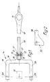
- the switching arm 10 shown in plan view in FIG. 1 is of conventional design, d. H. it has a vertical opening 11 at one end for receiving one on the (not shown) shift lever arranged ball joint and on the other End of a horizontal opening 12 for receiving a bearing pin 13.
- Shift arm adapter 14 For connection of the switching arm 12 with a (not shown) gear housing is used Shift arm adapter 14.
- the longitudinal axis of the shift arm 10 is in one the axis vertical plane containing the shift shaft 15 indicated by broken lines arranged.
- the switching arm adapter 14 is symmetrical about this vertical plane and includes two forked ends.
- the switching arm adapter 14 has a crossbar 16, of which two arms 17 in extend a small distance to the rear and two arms 18 at a greater distance extend forward.
- the two rear arms 17 and the two front arms 18 are parallel to the longitudinal axis of the shift arm 10 or the shift shaft 15.
- the two rear arms 17 are provided with bores 19 for receiving the bearing pin 13 provided, and the front arms 18 are provided with holes 20 for receiving (not shown) screws for rigid attachment to a corresponding contact surfaces provided area of the gearbox.
- the two front arms 18 have a special end profile 22. This End profile i22 is adapted to the shape of the gear housing, so that the Switch arm adapter 14 can be rotatably supported via the two front arms 18.
- the switching arm 10 is connected to the respective series Motor vehicle adapted switching arm adapter 14 articulated by the Bearing pin 13 in the aligned holes 19 and 12 of the two rear arms 17 and the switching arm 10 is used.
- the arranged in the switching arm 10 horizontal bore 12 has a slightly larger diameter than that Bearing pin 13 so that it can accommodate an elastic bearing sleeve 21.
- the shift arm adapter 14 on a part (not shown) of the transmission housing rigidly attached by screws (not shown) or similar fasteners through the holes 20 of the front arms 18 into corresponding Openings of the gear housing are used.
- the switching arm 10 is designed as a standard component, then the Dimensions of the shift arm adapter 14 to the respective vehicle model, d. H. on the distance between the mounting openings formed in the gear housing for the shift arm adapter and the bearing formed in the body for the shift arm be adjusted.
- the shift arm adapter being a standard component for the corresponding gearbox is and the switching arm 14 is adapted to the respective vehicle model.
- the switch arm 10 and the switch arm adapter 14 are preferred designed as cast components made of light metal.
Landscapes
- Engineering & Computer Science (AREA)
- General Engineering & Computer Science (AREA)
- Mechanical Engineering (AREA)
- Gear-Shifting Mechanisms (AREA)
Abstract
Description
- 10
- Schaltarm
- 11
- vertikale Öffnung
- 12
- horizontale Öffnung
- 13
- Lagerbolzen
- 14
- Schaltarmadapter
- 15
- Schaltwelle
- 16
- Quersteg
- 17
- hintere Arme
- 18
- vordere Arme
- 19
- Bohrungen in 17
- 20
- Bohrungen in 18
- 21
- Lagerhülse
- 22
- Endprofil
Claims (3)
- Vorrichtung zum Schalten eines Stufengetriebes in einem Kraftfahrzeug, umfassend einen Schaltarm, der an beiden Enden über Koppelelemente am Getriebegehäuse bzw. an der Karosserie des Fahrzeugs elastisch befestigt ist, einen Schalthebel, der über ein Kugelgelenk mit dem Schaltarm verbunden ist, und eine Schaltstange, die an beiden Enden mit dem freien Ende des Schalthebels bzw. mit einer aus dem Getriebegehäuse herausragenden Schaltwelle verbunden ist, wobei das dem Getriebegehäuse zugekehrte Ende des Schaltarms näherungsweise in der Höhenlage der Schaltwelle angeordnet und über Bolzenlager mit horizontaler Achse abgestützt ist, dadurch gekennzeichnet, daß ein zur Achse der Schaltwelle (15) symmetrischer Schaltarmadapter (14) vorgesehen ist, dessen beide Enden (17, 18) gabelförmig ausgebildet sind, daß ein die Schaltwelle (15) übergreifendes Ende (18) des Schaltarmadapters (14) mit dem Getriebegehäuse starr verbunden ist, daß das andere Ende (17) des Schaltarmadapters (14) den Schaltarm (10) übergreift, und daß ein horizontaler Bolzen (13) das gegabelte Ende (17) des Schaltarmadapters (14) und eine Buchse (12) des Schaltarms (10) durchsetzt.
- Vorrichtung nach Anspruch 1, dadurch gekennzeichnet, daß der Schaltarmadapter (14) ein an dem Getriebegehäuse starr befestigtes gesondertes Bauteil ist.
- Vorrichtung nach Anspruch 2, dadurch gekennzeichnet, daß das besagte eine gabelförmige Ende (18) des Schaltarmadapters (14) am Getriebegehäuse drehfest anliegt.
Applications Claiming Priority (2)
| Application Number | Priority Date | Filing Date | Title |
|---|---|---|---|
| DE10050686 | 2000-10-13 | ||
| DE2000150686 DE10050686A1 (de) | 2000-10-13 | 2000-10-13 | Vorrichtung zum Schalten eines Stufengetriebes in einem Kraftfahrzeug |
Publications (2)
| Publication Number | Publication Date |
|---|---|
| EP1197375A2 true EP1197375A2 (de) | 2002-04-17 |
| EP1197375A3 EP1197375A3 (de) | 2005-10-26 |
Family
ID=7659612
Family Applications (1)
| Application Number | Title | Priority Date | Filing Date |
|---|---|---|---|
| EP01122706A Ceased EP1197375A3 (de) | 2000-10-13 | 2001-09-21 | Vorrichtung zum Schalten eines Stufengetriebes in einem Kraftfahrzeug |
Country Status (2)
| Country | Link |
|---|---|
| EP (1) | EP1197375A3 (de) |
| DE (1) | DE10050686A1 (de) |
Family Cites Families (6)
| Publication number | Priority date | Publication date | Assignee | Title |
|---|---|---|---|---|
| JPS4839408B1 (de) * | 1970-12-31 | 1973-11-24 | ||
| JPS5813926B2 (ja) * | 1975-12-28 | 1983-03-16 | トヨタ自動車株式会社 | トランスミツシヨンコントロ−ルキコウ |
| JPH05141506A (ja) * | 1991-11-19 | 1993-06-08 | Mazda Motor Corp | 変速機構造 |
| DE19646648A1 (de) * | 1996-11-12 | 1998-05-14 | Daimler Benz Ag | Schaltvorrichtung für ein Zahnräderwechselgetriebe eines Kraftfahrzeuges |
| DE19851806A1 (de) * | 1998-01-30 | 1999-08-12 | Daimler Chrysler Ag | Schaltvorrichtung für ein Zahnräderwechselgetriebe |
| DE19805510A1 (de) * | 1998-02-11 | 1999-08-12 | Bayerische Motoren Werke Ag | Betätigungseinrichtung für ein Fahrzeuggetriebe |
-
2000
- 2000-10-13 DE DE2000150686 patent/DE10050686A1/de not_active Withdrawn
-
2001
- 2001-09-21 EP EP01122706A patent/EP1197375A3/de not_active Ceased
Non-Patent Citations (1)
| Title |
|---|
| None |
Also Published As
| Publication number | Publication date |
|---|---|
| EP1197375A3 (de) | 2005-10-26 |
| DE10050686A1 (de) | 2002-06-13 |
Similar Documents
| Publication | Publication Date | Title |
|---|---|---|
| DE2658274C3 (de) | Lagerung für einen Handschalthebel für Wechselgetriebe von Fahrzeugen | |
| EP1051577B1 (de) | Schaltvorrichtung für ein zahnräderwechselgetriebe | |
| DE602004004360T2 (de) | Fahrradgangschaltung mit einem in einem Gestängemechanismus angeordnetem Motor | |
| DE69103829T2 (de) | Vorrichtung zur Anpassung der Position eines Kraftfahrzeuggangschalthebels. | |
| EP0794364B1 (de) | Schaltvorrichtung für ein Zahnräderwechselgetriebe | |
| DE2336848C2 (de) | Mechanische Fernschaltvorrichtung für ein Kraftfahrzeugwechselgetriebe | |
| DE2743875A1 (de) | Vorrichtung zum schalten eines kraftfahrzeug-getriebes | |
| EP0825367B1 (de) | Betätigungseinrichtung für ein Kraftfahrzeuggetriebe | |
| EP0933563B1 (de) | Schaltvorrichtung für Wechselgetriebe von Kraftfahrzeugen | |
| DE10324383A1 (de) | Gangwechselbetätigungsvorrichtung für ein Getriebe | |
| EP1436178A1 (de) | Wischeranlage | |
| EP0936384A1 (de) | Betätigungseinrichtung für ein Fahrzeuggetriebe | |
| DE1575564A1 (de) | Steuerhebelhalterung | |
| DE10015772C1 (de) | Betätigungsvorrichtung zum Verstellen von Einstellpositionen eines Kraftfahrzeugsitzes | |
| DE19654273A1 (de) | Lenkradstellungseinstellvorrichtung für ein Fahrzeuglenksystem | |
| DE3634174A1 (de) | Vorrichtung zum daempfen von schwingungen in einer getriebeschaltvorrichtung fuer fahrzeuge | |
| DE19912746A1 (de) | Wischerantrieb mit einem reversierbaren Getriebemotor | |
| EP1197375A2 (de) | Vorrichtung zum Schalten eines Stufengetriebes in einem Kraftfahrzeug | |
| DE3109182C1 (de) | Verbindungselement für Schaltgestänge von Kraftfahrzeugen | |
| DE19543791C2 (de) | Schaltvorrichtung für das Wechselgetriebe in einem Kraftfahrzeug | |
| DE19901725B4 (de) | Montageanordnung für den Schalthebel eines Kraftfahrzeugs | |
| DE69200236T2 (de) | Mechanische Übertragung zwischen einem Schalthebel und dem Getriebe. | |
| DE29702964U1 (de) | Getriebeschalteinrichtung | |
| DE19905305A1 (de) | Wähl-/Schaltkoppelstange, insbesondere für eine Schaltvorrichtung eines Kraftfahrzeuggetriebes | |
| DD221133A1 (de) | Schalteinrichtung fuer fahrzeuggetriebe |
Legal Events
| Date | Code | Title | Description |
|---|---|---|---|
| PUAI | Public reference made under article 153(3) epc to a published international application that has entered the european phase |
Free format text: ORIGINAL CODE: 0009012 |
|
| AK | Designated contracting states |
Kind code of ref document: A2 Designated state(s): AT BE CH CY DE DK ES FI FR GB GR IE IT LI LU MC NL PT SE TR |
|
| AX | Request for extension of the european patent |
Free format text: AL;LT;LV;MK;RO;SI |
|
| PUAL | Search report despatched |
Free format text: ORIGINAL CODE: 0009013 |
|
| AK | Designated contracting states |
Kind code of ref document: A3 Designated state(s): AT BE CH CY DE DK ES FI FR GB GR IE IT LI LU MC NL PT SE TR |
|
| AX | Request for extension of the european patent |
Extension state: AL LT LV MK RO SI |
|
| 17P | Request for examination filed |
Effective date: 20050917 |
|
| AKX | Designation fees paid |
Designated state(s): DE FR GB IT |
|
| STAA | Information on the status of an ep patent application or granted ep patent |
Free format text: STATUS: THE APPLICATION HAS BEEN REFUSED |
|
| 18R | Application refused |
Effective date: 20060701 |