EP1197299A2 - Adaptateur pour attacher un réservoir à carburant sur des outils à moteur thermique - Google Patents
Adaptateur pour attacher un réservoir à carburant sur des outils à moteur thermique Download PDFInfo
- Publication number
- EP1197299A2 EP1197299A2 EP01402614A EP01402614A EP1197299A2 EP 1197299 A2 EP1197299 A2 EP 1197299A2 EP 01402614 A EP01402614 A EP 01402614A EP 01402614 A EP01402614 A EP 01402614A EP 1197299 A2 EP1197299 A2 EP 1197299A2
- Authority
- EP
- European Patent Office
- Prior art keywords
- fuel cell
- adapter
- latch
- locking
- locking tang
- Prior art date
- Legal status (The legal status is an assumption and is not a legal conclusion. Google has not performed a legal analysis and makes no representation as to the accuracy of the status listed.)
- Granted
Links
Images


Classifications
-
- F—MECHANICAL ENGINEERING; LIGHTING; HEATING; WEAPONS; BLASTING
- F23—COMBUSTION APPARATUS; COMBUSTION PROCESSES
- F23D—BURNERS
- F23D14/00—Burners for combustion of a gas, e.g. of a gas stored under pressure as a liquid
- F23D14/28—Burners for combustion of a gas, e.g. of a gas stored under pressure as a liquid in association with a gaseous fuel source, e.g. acetylene generator, or a container for liquefied gas
-
- B—PERFORMING OPERATIONS; TRANSPORTING
- B25—HAND TOOLS; PORTABLE POWER-DRIVEN TOOLS; MANIPULATORS
- B25C—HAND-HELD NAILING OR STAPLING TOOLS; MANUALLY OPERATED PORTABLE STAPLING TOOLS
- B25C1/00—Hand-held nailing tools; Nail feeding devices
- B25C1/04—Hand-held nailing tools; Nail feeding devices operated by fluid pressure, e.g. by air pressure
-
- B—PERFORMING OPERATIONS; TRANSPORTING
- B25—HAND TOOLS; PORTABLE POWER-DRIVEN TOOLS; MANIPULATORS
- B25C—HAND-HELD NAILING OR STAPLING TOOLS; MANUALLY OPERATED PORTABLE STAPLING TOOLS
- B25C1/00—Hand-held nailing tools; Nail feeding devices
- B25C1/08—Hand-held nailing tools; Nail feeding devices operated by combustion pressure
Definitions
- This invention relates to improvements in fuel cell adapter systems for use in combustion tools.
- a combustion gas-powered tool such as, for example, a combustion gas-powered fastener-driving tool.
- Such fastener-driving tools and such fuel cells are available commercially from ITW-Paslode (a division of Illinois Tool Works, Inc.) of Vernon Hills, Illinois, under its IMPULSE trademark.
- ITW-Paslode a division of Illinois Tool Works, Inc.
- IMPULSE trademark IMPULSE trademark
- a standard system for attaching a fuel cell to a combustion tool is known, i.e. placing the fuel cell into the combustion tool with a metering unit, and having no adapter.
- This system has the advantage of being compact, however it does not protect the female metering unit inlet from dirt and other debris. Also, when not using an adapter, a protective cap or blister pack is needed for transporting the fuel cell.
- one object of the present invention is to provide an improved fuel cell attachment system that protects the fuel cell from dirt and other debris while in use.
- Another object is to provide an improved fuel cell adapter that protects the fuel cell stem during transportation, thus eliminating the need for a protective cap or blister pack.
- a further object is to provide an improved fuel cell adapter that is able to provide visual identification of whether the fuel cell is unused or not.
- Yet another object of the present invention is to provide an improved combustion tool featuring a latch inside the combustion tool that releasably holds the fuel cell in an engaged position.
- Still another object is to provide an improved adapter for a fuel cell that cannot be removed from a fuel cell and reused with a generic fuel cell.
- the present fuel cell adapter system for a combustion tool which features an adapter having a frangible membrane on its free end to protect the fuel cell during transportation, a gripping formation configured for engagement with a latch, and a latching feature inside the combustion tool which releasably secures the fuel cell in engagement with the internal tool fuel metering valve.
- the present latching feature keeps the whole system compact in size and facilitates installation and removal of the fuel cell.
- the present adapter system also protects the fuel cell from dirt and debris while in use with the combustion tool. Further, the frangible membrane on the adapter visually indicates whether the fuel cell is unused. Another advantage of the present invention is that the user cannot remove and reuse the adapter on another fuel cell.
- the present invention provides a fuel cell adapter configured for connection to a fuel cell, including an adapter body having a generally cylindrical nozzle and a base configured for engagement upon the fuel cell, with the nozzle being connected to the base.
- the nozzle defines a passageway, and is provided with a frangible membrane blocking the passageway.
- a fuel cell adapter configured for connection to a fuel cell, including an adapter body having a generally cylindrical nozzle and a base configured for engagement upon the fuel cell, with the nozzle being connected to the base.
- the adapter body also has a gripping formation configured for engagement with a latch.
- the nozzle has a plurality of lugs and a plurality of support ribs.
- Each lug has a ramped configuration, extending from the free end toward the base, and has a truncated lug end.
- the support ribs each have a truncated rib end and are configured for connecting the nozzle to the base.
- a molded insert seal is housed in the passageway of the adapter body, and defines an axial passageway with a first end configured for receiving a stem and a second end provided with a pair of internal sealing rings located in the axial passageway.
- the present invention further provides a combustion tool including a housing which encloses a fuel metering valve and a fuel cell provided with an adapter configured for being accommodated in the housing for fluid communication with the metering valve.
- a latch is disposed in the housing for releasably securing the adapter in fluid communication with the metering valve.
- the latch includes a latch body having at least one locking tang movable between a closed position and an open position. There is also a release member for moving the locking tang to release the engagement with the adapter and permitting withdrawal of the fuel cell from the tool.
- a combustion-powered tool of the type suitable for use with the present invention is generally designated 10.
- the tool 10 includes a housing 11 enclosing a fuel metering valve 13, and a fuel cell chamber 12 which releasably houses a fuel cell 14.
- the construction and operation of the tool 10 is described in detail in the patents incorporated by reference and referred to above.
- a fuel cell adapter generally designated 16, is configured for connection to the fuel cell 14, and facilitates engagement of the fuel cell in the fuel cell chamber 12.
- An adapter body 18 has a generally cylindrical nozzle 20 and a base 22 configured for engagement upon the fuel cell 14, and the nozzle is connected to the base.
- the nozzle 20 has a free end 24 and defines a passageway 26, with a frangible membrane 28 blocking the passageway 26.
- This frangible membrane 28 has a hole 29 that allows for air escape, and it is preferably disposed at or adjacent the free end 24 of the nozzle 22 for visually indicating tampering when ruptured.
- the diameter of the hole 29 measures about 0.010 inches, however the size of the diameter may vary depending on the application.
- the nozzle 20 has a plurality of lugs 32 and a plurality of support ribs 34.
- the lugs 32 each have a ramped configuration, extending in an inclined configuration from the free end 24 toward the base 22, and each have a truncated lug end 36.
- the generally L-shaped support ribs 34 each have a truncated rib end 38, and are configured for connecting the nozzle 20 to the base 22.
- a feature of the present adapter 16 is that the spaced support ribs 34 are the fastening point of the nozzle 20 to the base 22 and thus provide a "break away" action if a user attempts to remove the adapter from the fuel cell 14. Thus the reuse of adapters 16 is prevented.
- the adapter 16 is provided with a gripping formation 40 which is configured for being engaged by a latch disposed in the fuel cell chamber 12 of the housing 11.
- This gripping formation 40 may have a variety of shapes. In the embodiment depicted in FIGs. 2-4, corresponding truncated lug ends 36 and the rib ends 38 of the lugs 32 and the support ribs 34 define a groove 40 that is disposed on the, nozzle 20.
- the adapter body 18 have a gripping formation 40 in the form of a groove as just described, it is also contemplated that the gripping formation is alternatively a rib or protrusion, generally radially extending from the adapter body 18. Such protrusions may form an annular rib or may also be individual, spaced, lugs or rib segments.
- the lugs 32 are radially spaced relative to each other, and the support ribs 34 are radially spaced relative to each other.
- the lugs 32 are also axially skewed, in other words, are not axially aligned relative to the opposing corresponding support ribs 34.
- a staggered relationship is defined between the lugs 32 and the support ribs 34.
- At least one barb 30 formed on the base 22 configured for frictionally engaging the fuel cell 14.
- the adapter body 18 houses a molded insert seal 44 which fits in the passageway 26.
- the molded insert seal 44 defines an axial passageway 46 (best seen in FIG. 8), and has a first end 48 configured for receiving a fuel cell stem 50, and a second end 52 provided with a pair of internal sealing rings 54 which are located in the axial passageway. It will be seen that, in the preferred embodiment, the first end 48 has a larger diameter than the second end 52.
- the molded insert 44 is fitted into the adapter body 18 where it is accommodated in the passageway 26. Then the adapter 16 is placed onto the fuel cell stem 50 so that a tip 56 of the fuel cell stem (FIGS. 2, 3 and 4) slides into the molded insert 44 and lies in between the pair of internal sealing rings 54.
- the base 22 is pushed downward onto a rolled seam 58 (FIGs. 2 and 3) of the fuel cell, so that the barbs 30 on the base hook under and frictionally engage the rolled seam.
- the adapter 16 is securely fit onto the fuel cell 14 with the barbs 30 under the rolled seam 58.
- frangible membrane 28 With the adapter 16 in place on the fuel cell 14 and before the system is placed in a combustion tool 10, the frangible membrane 28 will still be intact (un-pierced) which gives the adapter the advantage of protecting the fuel cell during transportation. Because of this advantage, there is no need for a protective fuel cell cap. Another advantage is that the intact frangible membrane 28 gives visual identification that the fuel cell 14 is unused.
- the fuel cell 14 is provided with the adapter 16 and it is configured for being accommodated in the housing 11 to be in fluid communication with the fuel metering valve 13.
- the fuel metering valve 13 that is shown is only one of several embodiments that are known in the art.
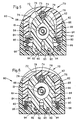
- a feature of the present system is a latch 60, which can be seen in FIGs. 4, 5 and 6 that is disposed in the housing 11 for releasably securing the adapter 16 in fluid communication with the fuel metering valve 13.
- the latch 60 includes a latch body 62 having at least one and preferably two locking tangs 64 which are movable between a closed position (FIG. 5) and an open position (FIG. 6). In the closed position, the tangs 64 secure the adapter 16 in the housing 11. Also included is a release member 70 for moving the locking tangs 64 to release the engagement with the adapter 16 and to permit withdrawal of the fuel cell 14 from the tool 10.
- the locking tangs 64 are biased to a closed position, although it is also contemplated that the locking tangs could be arranged to be biased in the open position. It is also preferred that the two locking tangs 64 in the latch 60 are disposed to be in an opposing relationship to each other.
- the preferred embodiment of the latch 60 is to have a push button 72 as the release member 70, with the push button having a generally circular raised boss 74 for engaging the locking tangs 64.
- the boss 74 is secured to the push button 72 by a friction fit with a lug 75, adhesive, or other fasteners that are well known in the art.
- each locking tang 64 has a contact end 76 with an inclined surface 78 for being progressively separated as the boss 74 is moved axially against a biasing force pressing the tangs to the closed position.
- the biasing force is provided by a pair of compression springs 80 located in a chamber 81 spanning the latch body 62 and the push button 72 to bias the button to an outward position. It is contemplated that the number, arrangement and strength of the springs may vary to suit the application.
- each locking tang 64 has an outside edge 82 defining a shoulder 84. There is also an inside edge 86 forming a surface 88 for engaging the groove 40 of the adapter 16.
- the surface 88 is arcuate in shape to better grasp the generally circular nozzle 20.
- the shape of the surface 88, and/or the edge 86 may change to positively engage alternative configurations of the gripping formation 40 as described above.
- the locking tangs 64 have a pivoting end 90 which is opposite the contact end 76.
- the pivoting end 90 has a hole 92 where a pivoting pin 94 is attached to the locking tangs 64, which holds them inside the latch body 62 and allows the locking tangs to pivotally move between the open and closed positions.
- the push button 72 is provided with a pair of holding pins 96 which each engage and abut the shoulders 84 of the locking tangs 64 to bias them into the closed position as seen in FIG. 5. These holding pins 96 also retain the push button 72 from escaping the housing 11 under the force of the springs 80. The holding pins 96 also act as a stop for the locking tangs 64. As seen in FIG.
- the locking tangs 64 are only allowed to pivotally open until the pivoting end 94 abuts the holding pin 96. Both the pivoting pins 94 and the holding pins 96 are disposed generally parallel to each other, and are generally normal to the plane defined by the locking tangs 64.
- the assembled fuel cell 14 and the adapter 16 are placed into the fuel cell chamber 12 of the tool 10.
- the nozzle 20 will come into contact with the latch 60, and the operator will then press the fuel cell 14 inward.
- the ramped configuration of the lugs 32 spread the locking tangs 64 apart.
- the locking tangs will close, and the inside edge 86 will engage the groove 40 or other configurations of the gripping formation of the adapter 16, so that the lug ends are positioned above the locking tangs and the truncated rib ends 38 are positioned below the locking tangs.
- the adapter 16 is securely held inside the tool 10 (best seen in FIG. 4).
- the fuel cell chamber 12 is seen in FIG. 4, where the fuel cell 14 and adapter 16 are locked in the latch 60.
- a fuel metering valve stem 98 pierces the frangible membrane 28 and is inserted into the molded insert seal 44, so that the fuel metering valve stem is aligned with, and preferably abuts the fuel cell stem 50 in between the pair of internal sealing rings 54. This arrangement enables sealed fluid communication between the fuel cell 14 and the fuel metering valve 13.
- the frangible membrane 28 has the advantage of protecting the fuel cell 14 from dirt and other debris. Since the latch 60 holds the adapter 16 and the fuel cell 14 in an engaged position with the fuel metering valve 13, the entire adapter system is very compact and there is no need for a cell chamber back door, or end cap, as is found on some models of combustion tools.
- the fuel metering valve stem 98 is separated from the molded insert seal 44 and it leaves the frangible membrane 28 pierced, which visually shows that the fuel cell 14 has been used.
- the design of the latch 60 is such that installation and removal of the fuel cell 14 is user friendly, and is comparable to installing and removing a battery of such combustion tools. Another advantage is that the adapter 16 cannot be removed from the fuel cell 14 without fracturing the support ribs 34, and therefore cannot be reused on another fuel cell.
- the present fuel cell adapter 16 and latch 60 provides an improved fuel cell adapter system that protects the fuel cell stem 50 during transportation, and also protects the fuel cell 14 from dirt and other debris while the tool 10 is in use.
- This improved fuel cell adapter system also keeps the whole system compact and makes installation and removal of the fuel cell 14 user friendly. Further, the present invention identifies if the fuel cell is unused or not, and also the adapter cannot be reused on a generic fuel cell.
Landscapes
- Engineering & Computer Science (AREA)
- Mechanical Engineering (AREA)
- Chemical & Material Sciences (AREA)
- Combustion & Propulsion (AREA)
- General Engineering & Computer Science (AREA)
- Physics & Mathematics (AREA)
- Fluid Mechanics (AREA)
- Portable Nailing Machines And Staplers (AREA)
- Feeding And Controlling Fuel (AREA)
- Fuel Cell (AREA)
Applications Claiming Priority (2)
| Application Number | Priority Date | Filing Date | Title |
|---|---|---|---|
| US689546 | 2000-10-12 | ||
| US09/689,546 US6523860B1 (en) | 2000-10-12 | 2000-10-12 | Fuel cell adapter system for combustion tools |
Publications (3)
| Publication Number | Publication Date |
|---|---|
| EP1197299A2 true EP1197299A2 (fr) | 2002-04-17 |
| EP1197299A3 EP1197299A3 (fr) | 2003-07-30 |
| EP1197299B1 EP1197299B1 (fr) | 2006-09-06 |
Family
ID=24768940
Family Applications (1)
| Application Number | Title | Priority Date | Filing Date |
|---|---|---|---|
| EP01402614A Expired - Lifetime EP1197299B1 (fr) | 2000-10-12 | 2001-10-10 | Adaptateur pour fixer un réservoir de carburant sur un outil entraîné par combustion et outil correspondant muni d'un loquet pour fixer l'adaptateur audit outil |
Country Status (13)
| Country | Link |
|---|---|
| US (2) | US6523860B1 (fr) |
| EP (1) | EP1197299B1 (fr) |
| JP (1) | JP4180813B2 (fr) |
| KR (1) | KR100777327B1 (fr) |
| CN (2) | CN100351048C (fr) |
| AT (1) | ATE338613T1 (fr) |
| AU (1) | AU760933B2 (fr) |
| BR (1) | BR0104492B1 (fr) |
| DE (1) | DE60122846T2 (fr) |
| HK (1) | HK1046385B (fr) |
| MX (1) | MXPA01010267A (fr) |
| NZ (1) | NZ514716A (fr) |
| TW (1) | TW514579B (fr) |
Cited By (12)
| Publication number | Priority date | Publication date | Assignee | Title |
|---|---|---|---|---|
| US6523860B1 (en) | 2000-10-12 | 2003-02-25 | Illinois Tool Works Inc. | Fuel cell adapter system for combustion tools |
| EP1310334A1 (fr) * | 2001-11-13 | 2003-05-14 | Illinois Tool Works Inc. | Adaptateur pour attacher à un réservoir à carburant sur des outils à moteur thermique ainsi que l'outil comprenant l'adapteur |
| FR2833686A1 (fr) * | 2001-12-18 | 2003-06-20 | Prospection & Inventions | Raccord de cartouche de gaz comprime et d'appareil de fixation |
| WO2003085766A1 (fr) * | 2002-04-10 | 2003-10-16 | Sfc Smart Fuel Cell Ag | Cartouche d'adaptation pouvant servir de cartouche de combustible |
| US6786378B2 (en) | 2002-01-09 | 2004-09-07 | Illinois Tool Works Inc. | Fastener tool having auxiliary fuel cell metering valve stem seal adaptor |
| EP1468788A1 (fr) * | 2003-04-15 | 2004-10-20 | Illinois Tool Works Inc. | Adaptateur pour un réservoir à carburant pour outil entraíné par gaz de combustion |
| AU2005203114B2 (en) * | 2001-11-13 | 2005-09-08 | Illinois Tool Works Inc. | Fuel cell adapter system for combustion tools |
| FR2870920A1 (fr) * | 2004-05-25 | 2005-12-02 | Prospection & Inventions | Adaptateur de raccordement d'une cartouche de gaz et d'un dispositif d'admission de gaz d'un appareil de fixation a gaz, la cartouche, l'electrovanne et l'appareil avec l'adaptateur |
| WO2005116508A1 (fr) * | 2004-05-25 | 2005-12-08 | Societe De Prospection Et D'inventions Techniques Spit | Adaptateur de connexion pour cartouche de gaz et dispositif d'admission de gaz sur liaison de systeme a gaz, cartouche, electrovanne et systeme equipe de l'adaptateur |
| FR2884896A1 (fr) * | 2005-04-26 | 2006-10-27 | Prospection & Inventions | Raccord d'etancheite et ensemble d'un organe de transmission, d'une cartouche de gaz et d'un adaptateur comprenant le raccord |
| EP1790438A1 (fr) * | 2005-11-25 | 2007-05-30 | HILTI Aktiengesellschaft | Réservoir à combustible pour outils de pose au combustion et accueil pour le réservoir dans l'outil de pose |
| US7942299B2 (en) | 2006-05-31 | 2011-05-17 | Black & Decker Inc. | Hand tool with belt or rafter hook |
Families Citing this family (33)
| Publication number | Priority date | Publication date | Assignee | Title |
|---|---|---|---|---|
| FR2838074B1 (fr) * | 2002-04-08 | 2004-09-17 | Prospection & Inventions | Raccord monobloc pour appareil de fixation a gaz comprime et cartouche de gaz comprime |
| US20050109972A1 (en) * | 2003-11-24 | 2005-05-26 | Powers Fasteners, Inc. | Connector for fuel cell |
| US7975893B2 (en) | 2004-04-02 | 2011-07-12 | Black & Decker Inc. | Return cord assembly for a power tool |
| ATE531484T1 (de) | 2004-04-02 | 2011-11-15 | Black & Decker Inc | Treiberkonfiguration für ein kraftbetriebenes werkzeug |
| US7726536B2 (en) | 2004-04-02 | 2010-06-01 | Black & Decker Inc. | Upper bumper configuration for a power tool |
| US8302833B2 (en) | 2004-04-02 | 2012-11-06 | Black & Decker Inc. | Power take off for cordless nailer |
| US8011549B2 (en) * | 2004-04-02 | 2011-09-06 | Black & Decker Inc. | Flywheel configuration for a power tool |
| US7686199B2 (en) | 2004-04-02 | 2010-03-30 | Black & Decker Inc. | Lower bumper configuration for a power tool |
| US8123099B2 (en) | 2004-04-02 | 2012-02-28 | Black & Decker Inc. | Cam and clutch configuration for a power tool |
| US10882172B2 (en) | 2004-04-02 | 2021-01-05 | Black & Decker, Inc. | Powered hand-held fastening tool |
| US8231039B2 (en) | 2004-04-02 | 2012-07-31 | Black & Decker Inc. | Structural backbone/motor mount for a power tool |
| US7478740B2 (en) * | 2006-06-30 | 2009-01-20 | Illinois Tool Works Inc. | Enhanced fuel passageway and adapter for combustion tool fuel cell |
| US7392922B2 (en) * | 2004-04-19 | 2008-07-01 | Illinois Tool Works Inc. | In-can fuel cell metering valve |
| US7571841B2 (en) * | 2004-04-19 | 2009-08-11 | Illinois Tool Works, Inc. | Interchangeable adapter for in-can and on-can fuel cells |
| US8002160B2 (en) * | 2004-08-30 | 2011-08-23 | Black & Decker Inc. | Combustion fastener |
| FR2884749B1 (fr) * | 2005-04-26 | 2007-06-29 | Prospection Et D Inv S Techniq | Carter de logement d'une source d'energie a actionnement manuel a macanismes d'ejection de la source |
| US7296719B1 (en) * | 2006-04-26 | 2007-11-20 | Illinois Tool Works Inc. | Fuel cell actuator and associated combustion tool |
| DE102006000233B4 (de) * | 2006-05-17 | 2015-05-13 | Hilti Aktiengesellschaft | Brennkraftbetriebenes Setzgarät |
| AU2008201129B2 (en) * | 2007-04-04 | 2011-01-27 | Hilti Ag | Combustion-operated setting tool |
| JP5104536B2 (ja) | 2008-05-16 | 2012-12-19 | マックス株式会社 | 燃料充填容器及びガス燃焼式打込み工具 |
| JP5384282B2 (ja) * | 2009-10-07 | 2014-01-08 | 株式会社マキタ | 燃焼式作業工具 |
| JP5741233B2 (ja) * | 2011-06-10 | 2015-07-01 | マックス株式会社 | 燃料容器保持構造 |
| JP5578206B2 (ja) * | 2012-08-03 | 2014-08-27 | マックス株式会社 | 燃料充填容器及びガス燃焼式打込み工具 |
| US9862083B2 (en) | 2014-08-28 | 2018-01-09 | Power Tech Staple and Nail, Inc. | Vacuum piston retention for a combustion driven fastener hand tool |
| US10759031B2 (en) | 2014-08-28 | 2020-09-01 | Power Tech Staple and Nail, Inc. | Support for elastomeric disc valve in combustion driven fastener hand tool |
| US10166666B2 (en) | 2015-11-25 | 2019-01-01 | Illinois Tool Works Inc. | Adapter for combustion tool fuel cells |
| TWI751176B (zh) * | 2016-08-31 | 2022-01-01 | 日商工機控股股份有限公司 | 打釘機、壓力調節器和打釘單元 |
| EP3652070B1 (fr) * | 2017-07-11 | 2023-05-17 | Safran Aerosystems | Systèmes de communication de réservoirs de carburant |
| US11466815B2 (en) * | 2017-10-06 | 2022-10-11 | Black & Decker Inc. | Hydrogen fuel canister |
| JP7093537B2 (ja) * | 2017-10-16 | 2022-06-30 | 日本パワーファスニング株式会社 | ガス燃焼式打ち込み工具用の燃料容器 |
| US11624314B2 (en) | 2018-08-21 | 2023-04-11 | Power Tech Staple and Nail, Inc. | Combustion chamber valve and fuel system for driven fastener hand tool |
| USD1001736S1 (en) | 2020-09-01 | 2023-10-17 | Illinois Tool Works Inc. | Fuel cell adapter for tool |
| US11978915B2 (en) | 2020-09-01 | 2024-05-07 | Illinois Tool Works Inc. | Combustion-powered fastener driving tool fuel cell adapter |
Citations (11)
| Publication number | Priority date | Publication date | Assignee | Title |
|---|---|---|---|---|
| US3035617A (en) * | 1957-01-09 | 1962-05-22 | American Nat Bank And Trust Co | Fuel transfer adapter with dual valve actuator |
| US3273610A (en) * | 1966-09-20 | Valved pressurized fluid dispensing receptacle with receptacle-attached fitting | ||
| GB1101918A (en) * | 1964-11-27 | 1968-02-07 | Bespak Industries Ltd | Improvements in and relating to pressurised dispensing devices |
| GB1311322A (en) * | 1970-02-06 | 1973-03-28 | Bespak Industries Ltd | Actuator nozzles for aerosol discharge valves of pressurised containers |
| FR2273594A1 (fr) * | 1974-06-05 | 1976-01-02 | Partiot Paul | Raccord souple adaptable sur les bombes aerosol pour permettre la sortie a distance du produit |
| FR2353793A1 (fr) * | 1975-04-17 | 1977-12-30 | Tobler Holding Ag | Dispositif de fixation, sur une cartouche a gaz, d'un appareil tel qu'un bruleur a farter les skis |
| US4483474A (en) * | 1981-01-22 | 1984-11-20 | Signode Corporation | Combustion gas-powered fastener driving tool |
| US5070858A (en) * | 1991-02-15 | 1991-12-10 | Wang Gin Pieng | Gas container connecting device for portable gas stove |
| EP0922902A1 (fr) * | 1997-11-28 | 1999-06-16 | Societe De Prospection Et D'inventions Techniques Spit | Raccord pour appareil de fixation à gaz comprimé et cartouche de gaz comprimé |
| EP0936031A1 (fr) * | 1998-02-13 | 1999-08-18 | Societe De Prospection Et D'inventions Techniques Spit | Appareil de fixation à gaz comprimé |
| WO2001035015A1 (fr) * | 1999-11-10 | 2001-05-17 | Walter Tosto Serbatoi S.P.A | Systeme de couplage de bouteilles de gaz pour distributeurs de gaz combustible |
Family Cites Families (38)
| Publication number | Priority date | Publication date | Assignee | Title |
|---|---|---|---|---|
| US1221650A (en) | 1916-12-18 | 1917-04-03 | Henry A Atkins | Garden and lawn tool. |
| FR826699A (fr) | 1936-12-22 | 1938-04-06 | Installation pour la dessication de l'air et autres gaz | |
| US3654965A (en) * | 1967-06-23 | 1972-04-11 | Pneumatiques Caoutchouc Mfg | Closure members for pipe sections |
| CH550354A (de) | 1972-04-10 | 1974-06-14 | Oetiker Hans | Bajonnet-leitungskupplung. |
| US3907012A (en) | 1974-05-31 | 1975-09-23 | Vca Corp | Adaptor fitting for blowing up inflatable devices |
| US4065029A (en) | 1974-09-05 | 1977-12-27 | Chernock Stephen P | Valve assembly |
| US3978844A (en) | 1975-04-07 | 1976-09-07 | Lawrence Peska Associates, Inc. | Cooking vessels having integral gas and burner assembly |
| AT343258B (de) | 1975-10-22 | 1978-05-26 | Lorch & Co Kg J | Druckluftaufbereitungsgerat in form von olvernebler, druckregler, abscheider u.dgl. |
| US4331277A (en) * | 1980-05-23 | 1982-05-25 | United States Surgical Corporation | Self-contained gas powered surgical stapler |
| US5782508A (en) * | 1980-10-29 | 1998-07-21 | Proprietary Technologies, Inc. | Swivelable quick connector assembly |
| IN157475B (fr) * | 1981-01-22 | 1986-04-05 | Signode Corp | |
| US4483473A (en) | 1983-05-02 | 1984-11-20 | Signode Corporation | Portable gas-powered fastener driving tool |
| US4491060A (en) | 1983-06-30 | 1985-01-01 | Otis Engineering Corporation | Cylinder connection |
| US4902043A (en) * | 1985-09-17 | 1990-02-20 | John T. Hoskins | Fluid coupling and seal assembly |
| GB8709421D0 (en) | 1987-04-21 | 1987-05-28 | Lucas Ind Plc | Pressure cylinder |
| FR2617941B1 (fr) | 1987-07-07 | 1989-10-27 | Applic Gaz Sa | Valve et recipient a valve |
| US4878595A (en) * | 1988-06-09 | 1989-11-07 | Plastic Technologies, Inc. | Tamper resistant wide mouth package with labyrinth seal |
| FR2636734B1 (fr) * | 1988-09-16 | 1990-11-30 | Cahors App Elec | Dispositif pour fixer un compteur d'eau sur une embase et procede s'y rapportant |
| US5029730A (en) | 1989-03-23 | 1991-07-09 | Sparklet Devices, Inc. | Weldably sealed oxygen container |
| US4911194A (en) * | 1989-10-23 | 1990-03-27 | Harsco Corporation | Thermally-sensitive coupling device |
| US5163598A (en) * | 1990-07-23 | 1992-11-17 | Rudolph Peters | Sternum stapling apparatus |
| DE4032204C2 (de) * | 1990-10-11 | 1999-10-21 | Hilti Ag | Setzgerät für Befestigungselemente |
| US5263439A (en) * | 1992-11-13 | 1993-11-23 | Illinois Tool Works Inc. | Fuel system for combustion-powered, fastener-driving tool |
| EP0680451B1 (fr) | 1993-01-19 | 1998-11-04 | Glaxo Group Limited | BOMBE AEROSOLE ET PROCéDé DE LA FABRICATION |
| ATE195583T1 (de) * | 1995-01-19 | 2000-09-15 | Legris Sa | Vorrichtung zum schnellen verbinden eines rohres mit einem starren element |
| US5979867A (en) * | 1995-02-09 | 1999-11-09 | Forgamex, S.A. De C.V. | Quick connect coupling for portable LP gas cylinders |
| GB9507768D0 (en) | 1995-04-13 | 1995-05-31 | Glaxo Group Ltd | Method of apparatus |
| GB9509490D0 (en) | 1995-05-10 | 1995-07-19 | Loral Europ | Gunfire simulator |
| US5567074A (en) * | 1995-09-19 | 1996-10-22 | Eaton Corporation | Tube clip |
| US5680980A (en) | 1995-11-27 | 1997-10-28 | Illinois Tool Works Inc. | Fuel injection system for combustion-powered tool |
| US5954345A (en) * | 1996-10-10 | 1999-09-21 | Chrysler Corporation | Grommet for transmission oil fill tube |
| US6016945A (en) | 1997-12-31 | 2000-01-25 | Porter-Cable Corporation | Internal combustion fastener driving tool manual recycler |
| US6032833A (en) | 1998-07-24 | 2000-03-07 | Olegnowicz; Israel | Non-throttling valve assembly |
| US6053005A (en) * | 1999-02-12 | 2000-04-25 | Boitnott; Gregory J. | Method of and kit for protecting the integrity of refrigeration systems |
| US6270919B1 (en) * | 1999-04-27 | 2001-08-07 | Eveready Battery Company, Inc. | Electrochemical cell having low profile seal assembly with anti-resealing vent |
| DE19937283A1 (de) | 1999-08-06 | 2001-02-15 | Hilti Ag | Ventilanordnung zur Abgabe von in Behältnissen unter Druck gelagerten fluiden Medien |
| US6302297B1 (en) * | 2000-09-06 | 2001-10-16 | Illinois Tool Works Inc. | External metering valve for a fuel cell |
| US6523860B1 (en) | 2000-10-12 | 2003-02-25 | Illinois Tool Works Inc. | Fuel cell adapter system for combustion tools |
-
2000
- 2000-10-12 US US09/689,546 patent/US6523860B1/en not_active Expired - Lifetime
-
2001
- 2001-09-28 KR KR1020010060331A patent/KR100777327B1/ko not_active IP Right Cessation
- 2001-10-08 AU AU78268/01A patent/AU760933B2/en not_active Ceased
- 2001-10-10 CN CNB031053343A patent/CN100351048C/zh not_active Expired - Fee Related
- 2001-10-10 CN CNB011415274A patent/CN1159137C/zh not_active Expired - Fee Related
- 2001-10-10 MX MXPA01010267A patent/MXPA01010267A/es active IP Right Grant
- 2001-10-10 BR BRPI0104492-3A patent/BR0104492B1/pt not_active IP Right Cessation
- 2001-10-10 NZ NZ514716A patent/NZ514716A/en not_active IP Right Cessation
- 2001-10-10 EP EP01402614A patent/EP1197299B1/fr not_active Expired - Lifetime
- 2001-10-10 DE DE60122846T patent/DE60122846T2/de not_active Expired - Lifetime
- 2001-10-10 AT AT01402614T patent/ATE338613T1/de not_active IP Right Cessation
- 2001-10-12 JP JP2001315524A patent/JP4180813B2/ja not_active Expired - Fee Related
- 2001-10-12 TW TW090125201A patent/TW514579B/zh not_active IP Right Cessation
-
2002
- 2002-04-02 US US10/115,065 patent/US6626344B2/en not_active Expired - Fee Related
- 2002-09-06 HK HK02106608.9A patent/HK1046385B/zh not_active IP Right Cessation
Patent Citations (11)
| Publication number | Priority date | Publication date | Assignee | Title |
|---|---|---|---|---|
| US3273610A (en) * | 1966-09-20 | Valved pressurized fluid dispensing receptacle with receptacle-attached fitting | ||
| US3035617A (en) * | 1957-01-09 | 1962-05-22 | American Nat Bank And Trust Co | Fuel transfer adapter with dual valve actuator |
| GB1101918A (en) * | 1964-11-27 | 1968-02-07 | Bespak Industries Ltd | Improvements in and relating to pressurised dispensing devices |
| GB1311322A (en) * | 1970-02-06 | 1973-03-28 | Bespak Industries Ltd | Actuator nozzles for aerosol discharge valves of pressurised containers |
| FR2273594A1 (fr) * | 1974-06-05 | 1976-01-02 | Partiot Paul | Raccord souple adaptable sur les bombes aerosol pour permettre la sortie a distance du produit |
| FR2353793A1 (fr) * | 1975-04-17 | 1977-12-30 | Tobler Holding Ag | Dispositif de fixation, sur une cartouche a gaz, d'un appareil tel qu'un bruleur a farter les skis |
| US4483474A (en) * | 1981-01-22 | 1984-11-20 | Signode Corporation | Combustion gas-powered fastener driving tool |
| US5070858A (en) * | 1991-02-15 | 1991-12-10 | Wang Gin Pieng | Gas container connecting device for portable gas stove |
| EP0922902A1 (fr) * | 1997-11-28 | 1999-06-16 | Societe De Prospection Et D'inventions Techniques Spit | Raccord pour appareil de fixation à gaz comprimé et cartouche de gaz comprimé |
| EP0936031A1 (fr) * | 1998-02-13 | 1999-08-18 | Societe De Prospection Et D'inventions Techniques Spit | Appareil de fixation à gaz comprimé |
| WO2001035015A1 (fr) * | 1999-11-10 | 2001-05-17 | Walter Tosto Serbatoi S.P.A | Systeme de couplage de bouteilles de gaz pour distributeurs de gaz combustible |
Cited By (31)
| Publication number | Priority date | Publication date | Assignee | Title |
|---|---|---|---|---|
| US6523860B1 (en) | 2000-10-12 | 2003-02-25 | Illinois Tool Works Inc. | Fuel cell adapter system for combustion tools |
| US6796478B2 (en) | 2000-10-12 | 2004-09-28 | Illinois Tool Works Inc. | Fuel cell adapter system for combustion tools |
| AU2005203114B2 (en) * | 2001-11-13 | 2005-09-08 | Illinois Tool Works Inc. | Fuel cell adapter system for combustion tools |
| EP1310334A1 (fr) * | 2001-11-13 | 2003-05-14 | Illinois Tool Works Inc. | Adaptateur pour attacher à un réservoir à carburant sur des outils à moteur thermique ainsi que l'outil comprenant l'adapteur |
| AU2002301761B2 (en) * | 2001-11-13 | 2005-09-08 | Illinois Tool Works Inc. | Fuel cell adapter system for combustion tools |
| FR2833686A1 (fr) * | 2001-12-18 | 2003-06-20 | Prospection & Inventions | Raccord de cartouche de gaz comprime et d'appareil de fixation |
| EP1321242A1 (fr) * | 2001-12-18 | 2003-06-25 | Societe De Prospection Et D'inventions Techniques Spit | Raccord de cartouche de gaz comprimé et d'appareil de fixation |
| US7314211B2 (en) | 2001-12-18 | 2008-01-01 | Societe De Prospection Et D'inventions Techniques Spit | Connector for a compressed-gas cannister and a fastening appliance |
| US6786378B2 (en) | 2002-01-09 | 2004-09-07 | Illinois Tool Works Inc. | Fastener tool having auxiliary fuel cell metering valve stem seal adaptor |
| KR100939072B1 (ko) * | 2002-01-09 | 2010-01-28 | 일리노이즈 툴 워크스 인코포레이티드 | 미터링 밸브 조립체, 미터링 밸브-공구 스템 조립체 및 연소 동력형 패스너 박는 공구 |
| US7757731B2 (en) | 2002-04-10 | 2010-07-20 | Sfc Smart Fuel Cell Ag | Adapter as alternative to fuel cartridges |
| EP1355371A1 (fr) * | 2002-04-10 | 2003-10-22 | SFC Smart Fuel Cell AG | Adaptateur comme alternative pour une cartouche à combustible |
| WO2003085766A1 (fr) * | 2002-04-10 | 2003-10-16 | Sfc Smart Fuel Cell Ag | Cartouche d'adaptation pouvant servir de cartouche de combustible |
| JP2004319509A (ja) * | 2003-04-15 | 2004-11-11 | Illinois Tool Works Inc <Itw> | 燃料電池アダプタに使用するためのインサートシール、燃料電池アダプタ及び燃焼式装置 |
| US7222765B2 (en) | 2003-04-15 | 2007-05-29 | Illinois Tool Works Inc. | Fuel cell adapter for a latch |
| EP1468788A1 (fr) * | 2003-04-15 | 2004-10-20 | Illinois Tool Works Inc. | Adaptateur pour un réservoir à carburant pour outil entraíné par gaz de combustion |
| AU2004201063B2 (en) * | 2003-04-15 | 2007-01-25 | Illinois Tool Works Inc. | Fuel cell adapter system for combustion tools |
| AU2005248142B2 (en) * | 2004-05-25 | 2008-07-31 | Societe De Prospection Et D'inventions Techniques Spit | Connecting adapter for a gas cartridge and a gas induction device of a gas fastening apparatus, the cartridge, the solenoid valve and the apparatus with the adapter |
| US8104798B2 (en) | 2004-05-25 | 2012-01-31 | Illinois Tool Works, Inc. | Connecting adapter for a gas cartridge and a gas induction device of a gas fastening apparatus, the cartridge, the solenoid valve and the apparatus with the adapter |
| WO2005116508A1 (fr) * | 2004-05-25 | 2005-12-08 | Societe De Prospection Et D'inventions Techniques Spit | Adaptateur de connexion pour cartouche de gaz et dispositif d'admission de gaz sur liaison de systeme a gaz, cartouche, electrovanne et systeme equipe de l'adaptateur |
| FR2870920A1 (fr) * | 2004-05-25 | 2005-12-02 | Prospection & Inventions | Adaptateur de raccordement d'une cartouche de gaz et d'un dispositif d'admission de gaz d'un appareil de fixation a gaz, la cartouche, l'electrovanne et l'appareil avec l'adaptateur |
| GB2439509A (en) * | 2005-04-26 | 2007-12-27 | Prospection & Inventions | Sealing connectorand assembly consisting of a transmission member, a gas cartridge and an adapter comprising the connector |
| WO2006114693A1 (fr) * | 2005-04-26 | 2006-11-02 | Societe De Prospection Et D'inventions Techniques Spit | Raccord d'etancheite et ensemble constitue d'un element de transmission, cartouche de gaz et adaptateur comprenant le raccord |
| FR2884896A1 (fr) * | 2005-04-26 | 2006-10-27 | Prospection & Inventions | Raccord d'etancheite et ensemble d'un organe de transmission, d'une cartouche de gaz et d'un adaptateur comprenant le raccord |
| ES2332847A1 (es) * | 2005-04-26 | 2010-02-12 | Societe De Prospection Et D'inventions Techniques | Conector de sellado y montaje que consiste en un miembro de transmision, un cartucho de gas y un adaptador que comprende el conector. |
| DK178208B1 (da) * | 2005-04-26 | 2015-08-24 | Prospection & Inventions | Tætningsforbindelseanordning og sammensat enhed bestående af et overførelseselement, en gaspatron og en adapter omfattende forbindelsesanordningen |
| GB2439509B (en) * | 2005-04-26 | 2010-12-15 | Prospection & Inventions | Sealing connector and assembly consisting of a transmission member, a gas cartridge and an adapter comprising the connector |
| AU2006235853B2 (en) * | 2005-11-25 | 2010-06-03 | Hilti Aktiengesellschaft | Propellant container for a combustion-engined setting tool and propellant container receptacle of the setting tool |
| KR101424250B1 (ko) * | 2005-11-25 | 2014-08-01 | 힐티 악티엔게젤샤프트 | 연소력으로 작동되는 세팅장치용 추진제통 및 세팅장치의추진제통 수용부 |
| EP1790438A1 (fr) * | 2005-11-25 | 2007-05-30 | HILTI Aktiengesellschaft | Réservoir à combustible pour outils de pose au combustion et accueil pour le réservoir dans l'outil de pose |
| US7942299B2 (en) | 2006-05-31 | 2011-05-17 | Black & Decker Inc. | Hand tool with belt or rafter hook |
Also Published As
| Publication number | Publication date |
|---|---|
| BR0104492B1 (pt) | 2010-06-15 |
| US20020108992A1 (en) | 2002-08-15 |
| CN1159137C (zh) | 2004-07-28 |
| HK1046385B (zh) | 2007-04-27 |
| MXPA01010267A (es) | 2004-11-10 |
| US6626344B2 (en) | 2003-09-30 |
| EP1197299A3 (fr) | 2003-07-30 |
| EP1197299B1 (fr) | 2006-09-06 |
| BR0104492A (pt) | 2002-05-28 |
| TW514579B (en) | 2002-12-21 |
| ATE338613T1 (de) | 2006-09-15 |
| US6523860B1 (en) | 2003-02-25 |
| NZ514716A (en) | 2003-05-30 |
| CN1519083A (zh) | 2004-08-11 |
| KR100777327B1 (ko) | 2007-11-20 |
| AU760933B2 (en) | 2003-05-22 |
| JP4180813B2 (ja) | 2008-11-12 |
| DE60122846D1 (de) | 2006-10-19 |
| JP2002192479A (ja) | 2002-07-10 |
| AU7826801A (en) | 2002-04-18 |
| CN1347791A (zh) | 2002-05-08 |
| HK1046385A1 (en) | 2003-01-10 |
| CN100351048C (zh) | 2007-11-28 |
| KR20020029302A (ko) | 2002-04-18 |
| DE60122846T2 (de) | 2007-04-19 |
Similar Documents
| Publication | Publication Date | Title |
|---|---|---|
| US6626344B2 (en) | Fuel cell adapter system for combustion tools | |
| CA2410334C (fr) | Systeme adaptateur de piles a combustible pour outil de combustion | |
| CA2460551C (fr) | Adaptateur de pile a combustible pour outils de combustion | |
| AU2003200481B2 (en) | Fuel cell adapter system for combustion tools | |
| AU2005203114B2 (en) | Fuel cell adapter system for combustion tools |
Legal Events
| Date | Code | Title | Description |
|---|---|---|---|
| PUAI | Public reference made under article 153(3) epc to a published international application that has entered the european phase |
Free format text: ORIGINAL CODE: 0009012 |
|
| AK | Designated contracting states |
Kind code of ref document: A2 Designated state(s): AT BE CH CY DE DK ES FI FR GB GR IE IT LI LU MC NL PT SE TR |
|
| AX | Request for extension of the european patent |
Free format text: AL;LT;LV;MK;RO;SI |
|
| RIC1 | Information provided on ipc code assigned before grant |
Ipc: 7B 25C 1/08 B Ipc: 7F 23D 14/28 B Ipc: 7B 25C 1/06 A Ipc: 7B 65D 83/14 B |
|
| PUAL | Search report despatched |
Free format text: ORIGINAL CODE: 0009013 |
|
| AK | Designated contracting states |
Designated state(s): AT BE CH CY DE DK ES FI FR GB GR IE IT LI LU MC NL PT SE TR |
|
| AX | Request for extension of the european patent |
Extension state: AL LT LV MK RO SI |
|
| 17P | Request for examination filed |
Effective date: 20040130 |
|
| AKX | Designation fees paid |
Designated state(s): AT BE CH CY DE DK ES FI FR GB GR IE IT LI LU MC NL PT SE TR |
|
| 17Q | First examination report despatched |
Effective date: 20041109 |
|
| GRAP | Despatch of communication of intention to grant a patent |
Free format text: ORIGINAL CODE: EPIDOSNIGR1 |
|
| GRAC | Information related to communication of intention to grant a patent modified |
Free format text: ORIGINAL CODE: EPIDOSCIGR1 |
|
| RTI1 | Title (correction) |
Free format text: FUEL CELL ADAPTER FOR A COMBUSTION TOOL AND COMBUSTION TOOL WITH A LATCH FOR SECURING THE ADAPTER TO THE COMBUSTION TOOL |
|
| GRAS | Grant fee paid |
Free format text: ORIGINAL CODE: EPIDOSNIGR3 |
|
| GRAA | (expected) grant |
Free format text: ORIGINAL CODE: 0009210 |
|
| STAA | Information on the status of an ep patent application or granted ep patent |
Free format text: STATUS: THE PATENT HAS BEEN GRANTED |
|
| AK | Designated contracting states |
Kind code of ref document: B1 Designated state(s): AT BE CH CY DE DK ES FI FR GB GR IE IT LI LU MC NL PT SE TR |
|
| PG25 | Lapsed in a contracting state [announced via postgrant information from national office to epo] |
Ref country code: IT Free format text: LAPSE BECAUSE OF FAILURE TO SUBMIT A TRANSLATION OF THE DESCRIPTION OR TO PAY THE FEE WITHIN THE PRESCRIBED TIME-LIMIT;WARNING: LAPSES OF ITALIAN PATENTS WITH EFFECTIVE DATE BEFORE 2007 MAY HAVE OCCURRED AT ANY TIME BEFORE 2007. THE CORRECT EFFECTIVE DATE MAY BE DIFFERENT FROM THE ONE RECORDED. Effective date: 20060906 Ref country code: CH Free format text: LAPSE BECAUSE OF FAILURE TO SUBMIT A TRANSLATION OF THE DESCRIPTION OR TO PAY THE FEE WITHIN THE PRESCRIBED TIME-LIMIT Effective date: 20060906 Ref country code: LI Free format text: LAPSE BECAUSE OF FAILURE TO SUBMIT A TRANSLATION OF THE DESCRIPTION OR TO PAY THE FEE WITHIN THE PRESCRIBED TIME-LIMIT Effective date: 20060906 Ref country code: NL Free format text: LAPSE BECAUSE OF FAILURE TO SUBMIT A TRANSLATION OF THE DESCRIPTION OR TO PAY THE FEE WITHIN THE PRESCRIBED TIME-LIMIT Effective date: 20060906 Ref country code: FI Free format text: LAPSE BECAUSE OF FAILURE TO SUBMIT A TRANSLATION OF THE DESCRIPTION OR TO PAY THE FEE WITHIN THE PRESCRIBED TIME-LIMIT Effective date: 20060906 |
|
| REG | Reference to a national code |
Ref country code: GB Ref legal event code: FG4D |
|
| REG | Reference to a national code |
Ref country code: CH Ref legal event code: EP |
|
| PG25 | Lapsed in a contracting state [announced via postgrant information from national office to epo] |
Ref country code: IE Free format text: LAPSE BECAUSE OF NON-PAYMENT OF DUE FEES Effective date: 20061010 |
|
| REG | Reference to a national code |
Ref country code: IE Ref legal event code: FG4D |
|
| REF | Corresponds to: |
Ref document number: 60122846 Country of ref document: DE Date of ref document: 20061019 Kind code of ref document: P |
|
| PGFP | Annual fee paid to national office [announced via postgrant information from national office to epo] |
Ref country code: CH Payment date: 20061027 Year of fee payment: 6 |
|
| PG25 | Lapsed in a contracting state [announced via postgrant information from national office to epo] |
Ref country code: MC Free format text: LAPSE BECAUSE OF NON-PAYMENT OF DUE FEES Effective date: 20061031 |
|
| PG25 | Lapsed in a contracting state [announced via postgrant information from national office to epo] |
Ref country code: DK Free format text: LAPSE BECAUSE OF FAILURE TO SUBMIT A TRANSLATION OF THE DESCRIPTION OR TO PAY THE FEE WITHIN THE PRESCRIBED TIME-LIMIT Effective date: 20061206 |
|
| PG25 | Lapsed in a contracting state [announced via postgrant information from national office to epo] |
Ref country code: ES Free format text: LAPSE BECAUSE OF FAILURE TO SUBMIT A TRANSLATION OF THE DESCRIPTION OR TO PAY THE FEE WITHIN THE PRESCRIBED TIME-LIMIT Effective date: 20061217 |
|
| REG | Reference to a national code |
Ref country code: SE Ref legal event code: TRGR |
|
| PG25 | Lapsed in a contracting state [announced via postgrant information from national office to epo] |
Ref country code: PT Free format text: LAPSE BECAUSE OF FAILURE TO SUBMIT A TRANSLATION OF THE DESCRIPTION OR TO PAY THE FEE WITHIN THE PRESCRIBED TIME-LIMIT Effective date: 20070219 |
|
| NLV1 | Nl: lapsed or annulled due to failure to fulfill the requirements of art. 29p and 29m of the patents act | ||
| REG | Reference to a national code |
Ref country code: CH Ref legal event code: PL |
|
| ET | Fr: translation filed | ||
| REG | Reference to a national code |
Ref country code: HK Ref legal event code: GR Ref document number: 1046385 Country of ref document: HK |
|
| PLBE | No opposition filed within time limit |
Free format text: ORIGINAL CODE: 0009261 |
|
| STAA | Information on the status of an ep patent application or granted ep patent |
Free format text: STATUS: NO OPPOSITION FILED WITHIN TIME LIMIT |
|
| 26N | No opposition filed |
Effective date: 20070607 |
|
| PGFP | Annual fee paid to national office [announced via postgrant information from national office to epo] |
Ref country code: IT Payment date: 20071026 Year of fee payment: 7 Ref country code: AT Payment date: 20070919 Year of fee payment: 7 |
|
| PGFP | Annual fee paid to national office [announced via postgrant information from national office to epo] |
Ref country code: BE Payment date: 20071107 Year of fee payment: 7 |
|
| PG25 | Lapsed in a contracting state [announced via postgrant information from national office to epo] |
Ref country code: GR Free format text: LAPSE BECAUSE OF FAILURE TO SUBMIT A TRANSLATION OF THE DESCRIPTION OR TO PAY THE FEE WITHIN THE PRESCRIBED TIME-LIMIT Effective date: 20061207 |
|
| PG25 | Lapsed in a contracting state [announced via postgrant information from national office to epo] |
Ref country code: LU Free format text: LAPSE BECAUSE OF NON-PAYMENT OF DUE FEES Effective date: 20061010 Ref country code: TR Free format text: LAPSE BECAUSE OF FAILURE TO SUBMIT A TRANSLATION OF THE DESCRIPTION OR TO PAY THE FEE WITHIN THE PRESCRIBED TIME-LIMIT Effective date: 20060906 |
|
| PG25 | Lapsed in a contracting state [announced via postgrant information from national office to epo] |
Ref country code: CY Free format text: LAPSE BECAUSE OF FAILURE TO SUBMIT A TRANSLATION OF THE DESCRIPTION OR TO PAY THE FEE WITHIN THE PRESCRIBED TIME-LIMIT Effective date: 20060906 |
|
| BERE | Be: lapsed |
Owner name: ILLINOIS TOOL WORKS INC. Effective date: 20081031 |
|
| PG25 | Lapsed in a contracting state [announced via postgrant information from national office to epo] |
Ref country code: AT Free format text: LAPSE BECAUSE OF NON-PAYMENT OF DUE FEES Effective date: 20081010 Ref country code: IT Free format text: LAPSE BECAUSE OF NON-PAYMENT OF DUE FEES Effective date: 20081010 |
|
| PG25 | Lapsed in a contracting state [announced via postgrant information from national office to epo] |
Ref country code: BE Free format text: LAPSE BECAUSE OF NON-PAYMENT OF DUE FEES Effective date: 20081031 |
|
| PGFP | Annual fee paid to national office [announced via postgrant information from national office to epo] |
Ref country code: SE Payment date: 20091028 Year of fee payment: 9 |
|
| PG25 | Lapsed in a contracting state [announced via postgrant information from national office to epo] |
Ref country code: SE Free format text: LAPSE BECAUSE OF NON-PAYMENT OF DUE FEES Effective date: 20101011 |
|
| PGFP | Annual fee paid to national office [announced via postgrant information from national office to epo] |
Ref country code: DE Payment date: 20141029 Year of fee payment: 14 Ref country code: FR Payment date: 20141017 Year of fee payment: 14 Ref country code: GB Payment date: 20141027 Year of fee payment: 14 |
|
| REG | Reference to a national code |
Ref country code: DE Ref legal event code: R119 Ref document number: 60122846 Country of ref document: DE |
|
| GBPC | Gb: european patent ceased through non-payment of renewal fee |
Effective date: 20151010 |
|
| PG25 | Lapsed in a contracting state [announced via postgrant information from national office to epo] |
Ref country code: GB Free format text: LAPSE BECAUSE OF NON-PAYMENT OF DUE FEES Effective date: 20151010 Ref country code: DE Free format text: LAPSE BECAUSE OF NON-PAYMENT OF DUE FEES Effective date: 20160503 |
|
| REG | Reference to a national code |
Ref country code: FR Ref legal event code: ST Effective date: 20160630 |
|
| PG25 | Lapsed in a contracting state [announced via postgrant information from national office to epo] |
Ref country code: FR Free format text: LAPSE BECAUSE OF NON-PAYMENT OF DUE FEES Effective date: 20151102 |