EP1194663B1 - Wandverkleidungsplatte - Google Patents
Wandverkleidungsplatte Download PDFInfo
- Publication number
- EP1194663B1 EP1194663B1 EP99959414A EP99959414A EP1194663B1 EP 1194663 B1 EP1194663 B1 EP 1194663B1 EP 99959414 A EP99959414 A EP 99959414A EP 99959414 A EP99959414 A EP 99959414A EP 1194663 B1 EP1194663 B1 EP 1194663B1
- Authority
- EP
- European Patent Office
- Prior art keywords
- panel
- drainage channel
- wall cladding
- groove
- locking system
- Prior art date
- Legal status (The legal status is an assumption and is not a legal conclusion. Google has not performed a legal analysis and makes no representation as to the accuracy of the status listed.)
- Expired - Lifetime
Links
- 238000005253 cladding Methods 0.000 claims description 47
- 229920002430 Fibre-reinforced plastic Polymers 0.000 claims 1
- 238000000748 compression moulding Methods 0.000 claims 1
- 239000011151 fibre-reinforced plastic Substances 0.000 claims 1
- XLYOFNOQVPJJNP-UHFFFAOYSA-N water Substances O XLYOFNOQVPJJNP-UHFFFAOYSA-N 0.000 abstract description 12
- 238000007493 shaping process Methods 0.000 abstract 1
- 238000013459 approach Methods 0.000 description 3
- 238000004140 cleaning Methods 0.000 description 1
- 239000002131 composite material Substances 0.000 description 1
- 238000011109 contamination Methods 0.000 description 1
- 239000003657 drainage water Substances 0.000 description 1
- 239000000428 dust Substances 0.000 description 1
- 210000003746 feather Anatomy 0.000 description 1
- 239000011152 fibreglass Substances 0.000 description 1
- 238000003780 insertion Methods 0.000 description 1
- 230000037431 insertion Effects 0.000 description 1
- 238000002386 leaching Methods 0.000 description 1
- 238000000034 method Methods 0.000 description 1
- 230000035515 penetration Effects 0.000 description 1
- 239000011505 plaster Substances 0.000 description 1
- 238000003825 pressing Methods 0.000 description 1
- 239000004575 stone Substances 0.000 description 1
Images

Classifications
-
- E—FIXED CONSTRUCTIONS
- E04—BUILDING
- E04F—FINISHING WORK ON BUILDINGS, e.g. STAIRS, FLOORS
- E04F13/00—Coverings or linings, e.g. for walls or ceilings
- E04F13/07—Coverings or linings, e.g. for walls or ceilings composed of covering or lining elements; Sub-structures therefor; Fastening means therefor
- E04F13/08—Coverings or linings, e.g. for walls or ceilings composed of covering or lining elements; Sub-structures therefor; Fastening means therefor composed of a plurality of similar covering or lining elements
- E04F13/18—Coverings or linings, e.g. for walls or ceilings composed of covering or lining elements; Sub-structures therefor; Fastening means therefor composed of a plurality of similar covering or lining elements of organic plastics with or without reinforcements or filling materials or with an outer layer of organic plastics with or without reinforcements or filling materials; plastic tiles
- E04F13/185—Coverings or linings, e.g. for walls or ceilings composed of covering or lining elements; Sub-structures therefor; Fastening means therefor composed of a plurality of similar covering or lining elements of organic plastics with or without reinforcements or filling materials or with an outer layer of organic plastics with or without reinforcements or filling materials; plastic tiles with an outer layer imitating natural stone, brick work, tiled surface or the like
-
- E—FIXED CONSTRUCTIONS
- E04—BUILDING
- E04C—STRUCTURAL ELEMENTS; BUILDING MATERIALS
- E04C2/00—Building elements of relatively thin form for the construction of parts of buildings, e.g. sheet materials, slabs, or panels
- E04C2/02—Building elements of relatively thin form for the construction of parts of buildings, e.g. sheet materials, slabs, or panels characterised by specified materials
- E04C2/10—Building elements of relatively thin form for the construction of parts of buildings, e.g. sheet materials, slabs, or panels characterised by specified materials of wood, fibres, chips, vegetable stems, or the like; of plastics; of foamed products
- E04C2/20—Building elements of relatively thin form for the construction of parts of buildings, e.g. sheet materials, slabs, or panels characterised by specified materials of wood, fibres, chips, vegetable stems, or the like; of plastics; of foamed products of plastics
-
- E—FIXED CONSTRUCTIONS
- E04—BUILDING
- E04F—FINISHING WORK ON BUILDINGS, e.g. STAIRS, FLOORS
- E04F13/00—Coverings or linings, e.g. for walls or ceilings
- E04F13/07—Coverings or linings, e.g. for walls or ceilings composed of covering or lining elements; Sub-structures therefor; Fastening means therefor
- E04F13/08—Coverings or linings, e.g. for walls or ceilings composed of covering or lining elements; Sub-structures therefor; Fastening means therefor composed of a plurality of similar covering or lining elements
- E04F13/0864—Coverings or linings, e.g. for walls or ceilings composed of covering or lining elements; Sub-structures therefor; Fastening means therefor composed of a plurality of similar covering or lining elements composed of superposed elements which overlap each other and of which the flat outer surface includes an acute angle with the surface to cover
Definitions
- the invention relates to a wall cladding panel with a closure system, wherein the wall cladding panels have a panel base body which its visible side provided with a surface structure and / or -Profiltechnik is, wherein the plate body with its lateral plate edges the Slab edges of adjacent wall cladding panels and / or engages under and wherein at a lateral vertical edge of the plate to the plate body a drainage channel is formed, wherein the lower horizontal plate edge with a spring and the top horizontal plate edge with a on the Feather tuned groove is provided and wherein the groove at their groove ends in the drainage channel is initiated.
- Such a wall cladding panel is known from US 3,593,479, which be provided with a closure system and laid in a composite can.
- the wall panel is on the panel body with lateral Plate edges provided to the plate edges of laterally lined wall cladding panels connect.
- a vertical plate edge has a drainage channel on, which extends along the edge of the plate and the edge of the plate the adjacent wall cladding panel overlaps, leaving a Siphon-like closure arises, the penetration of water from the Drainage channel on the back of the plate prevented. Because the drainage channel in the region of the lower horizontal plate edge above the groove of adjoining wall cladding panel is arranged transversely, flows from the Drainage drainage water at the front of the adjoining Wall cladding panel off. This leads through the leaching of dust, the accumulates in the drainage channel, to contamination of the front panels, so that these then only by elaborate cleaning measures have it removed.
- the wall cladding panel with a drainage channel so to include in the locking system that in the misplaced Wall covering controls the water entering the drainage channel is discharged without connecting to the back and front To get wall cladding panels.
- This object is achieved in that the drainage channel in the groove of the lower tiered wall panel is initiated.
- the collected water in the drainage channel guided and not, as in the prior art, derived over the visible side. Rather, the water discharge is targeted at the lower horizontal end of a Cladding.
- the knowledge was used made in the drainage channel even in very heavy rainfall only the smallest amounts of rainwater penetrate into the drainage channel, so that with a corresponding cross-sectional dimensioning of the drainage channel Reliable water drainage even with very large facade cladding is always possible without a water retention occurs.
- the drainage channel is covered by an extension tongue, the Plate edge of the adjacent wall cladding panel arranged and with provided in the direction of the drainage channel projecting deflecting is, and wherein the deflecting strip spaced from the bottom of the drainage channel is arranged.
- the Umlenkolin forms a shield that prevents in a driving rain laterally incident rainwater with too high kinetic energy can get into the drainage channel. This ensures that no water can get onto the wall panel plate back.
- One possible embodiment of the invention provides that the drainage channel in the Connection to the bottom of the side of a rib-like bridge and the Ptatten emotions is limited, that the bottom in the region of the lower edge of the plate with is provided in the direction of the plate front projection protruding and that the step offset of the floor created with the projection over a, with respect to the bottom surface inclined draft, is balanced.
- a simple structural design in the groove area results when provided is that the groove on the back with a fastening strip and front is completed with a groove wall, and that the Befestigunsang with Attachment is provided.
- a closure system To the collected water in a simple way in the adjacent drainage channel to be able to pass, a closure system according to the invention be characterized in that the adjacent at the upper edge of the plate edge Facade panels molded fixing strips in the area above the groove overlap, and that the drainage channel over the overlap area all the way up led to the groove.
- a conceivable invention alternative can be characterized in that the Front side of the fastening strip opposite the adjoining bottom of the Drainage channel projects that the fastening strip of the connected Facade plate with its back on the bottom of the drainage channel rests, and that the front sides of the fixing strips flush with each other in one another pass.
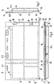
- a wall covering plate is shown, which is a plate body 14 has.
- the plate main body 14 is provided with a surface structure or profiling provided.
- a surface structure or profiling For example, conceivable is a plaster structure or to imitate a stone structure on the plate body.
- the wall panel consists of a glass fiber reinforced plastic, which in the Pressing process is made.
- a spring 18 At the bottom horizontal edge of the wall cladding panel is a spring 18 before.
- Fig. 2 has the Spring 18 a front, inclined insertion bevel.
- At the upper horizontal edge joins the plate body 14 a groove 12 at.
- the groove 12 is doing on the back side of a fastening strip 11 and on the front side of a groove wall 11.4 limited.
- the fastening strip 11 is provided with fastening receptacles 11.1, 11.2 provided.
- the fastening receptacles 11.1, 11.2 formed as breakthroughs.
- the mounting shots 11.1 are used to hold nails, the mounting receptacles 11.2 for Pick up screws.
- Fig. 1 is the right panel edge of the wall cladding panel a drainage channel 20 integrally formed.
- the Drainage channel 20 has a bottom 21, at the side of a web 22nd and connect the disk base 14. Thus limit the bridge 22 and the Plate body 14, the drainage channel 20.
- At the bottom edge of the plate points the bottom 21 of the drainage channel 20 offset to the front side Projection 24 on.
- the bottom 21 is on an inclined draft 23 on this Led projection 24.
- two lugs 25 are formed, the are formed rib-like.
- An approach 25 is in the upper plate area, the other approach 25 formed on the projection 24.
- the plate body 14 is at the left edge of the plate provided with an extension tongue 10.
- the extension tongue 10 is on provided with a bend at their free end, which towards the back the wall cladding panel is addressed.
- the fold forms a deflection strip 17 (see Fig. 2).
- the scheme for mounting the wall cladding panel described above on a facade will become more apparent in the following with reference to FIG. 4 explained.
- the lower left one can first Wall cladding panel on the facade under the help of the fixing strip 11 are attached.
- the lower right Attach facade panel Here, the right bottom wall cladding panel with its fastening strip 11 on the bottom 21 of the drainage channel 20th hung up.
- the fastening strip 11 has a recess 11.3, the ensures that the front sides 13 of the fixing strips 11 flush with the surface merge.
- the deflection bar 17 is in the direction of the bottom 21 of the Drainage channel 20, but does not touch it.
- the web 22 is in Direction to the plate back 15 of the right bottom wall panel but does not affect them.
- the deflection strip 17 and the web 22nd a maze. This prevents water from the front of the plate on the Plate back 15 can get.
- the two bottom wall cladding panels can first be the upper left wall cladding panel plant. This is with its spring 18 in the groove 12 of the left lower wall cladding panel set.
- the drainage channel 20 is in the range its projection 24 in the grooves of the underlying wall cladding panels initiated.
- the right upper wall cladding panel can be attached be, with their spring 18 in the groove 12 of the lower right Wall cladding panel is set.
- the deflection bar 17 of the upper right Wall cladding plate engages in the region of the drainage channel 20, again not touching the ground 21.
- the Deflection bar 17 provided with a recess 16.
- the lugs 25 provide during assembly of the wall cladding panels a Mounting aid.
- the deflection strip 17 can on the inside of the lugs 25 be struck so that a predetermined plate spacing maintained can be.
Landscapes
- Engineering & Computer Science (AREA)
- Architecture (AREA)
- Civil Engineering (AREA)
- Structural Engineering (AREA)
- Life Sciences & Earth Sciences (AREA)
- Wood Science & Technology (AREA)
- Finishing Walls (AREA)
- Glass Compositions (AREA)
- Connection Of Plates (AREA)
- Dowels (AREA)
- Vehicle Interior And Exterior Ornaments, Soundproofing, And Insulation (AREA)
Description
- Fig. 1
- eine Wandverkleidungsplatte in Frontansicht,
- Fig. 2
- die Wandverkleidungsplatte gemäß Fig. 1 in Ansicht von links,
- Fig. 3
- die Wandverkleidungsplatte gemäß Fig. 1 und 2 in Draufsicht und
- Fig. 4
- in Explosionsdarstellung vier aneinander montierbare Wandverkleidungsplatten.
Claims (8)
- Wandverkleidungsplatte mit einem Verschlußsystem, wobei die Wandverkleidungsplatte einen Plattengrundkörper (14) aufweist, der auf seiner Sichtseite mit einer Oberflächen-Struktur und/oder -Profilierung versehen ist, wobei der Plattengrundkörper (14) mit seinen seitlichen Plattenrändern die Plattenränder benachbarter Wandverkleidungsplatten über- und/oder untergreift, und wobei an einem seitlichen vertikalen Plattenrand an den Plattengrundkörper (14) eine Entwässerungsrinne (20) angeformt ist, wobei der untere horizontale Plattenrand mit einer Feder (18) und der obere horizontale Plattenrand mit einer auf die Feder (18) abgestimmten Nut (12) versehen ist und wobei die Nut (12) an ihren Nutenden in die Entwässerungsrinne (20) eingeleitet ist,
dadurch gekennzeichnet, dass die Entwässerungsrinne (20) geeignet ist, in die Nut (12) einer unteren angereihten Wandverkteidungsplatte einzuleiten. - Wandverkleidungsplatte mit einem Verschlußsystem nach Anspruch 1,
dadurch gekennzeichnet, daß die Entwässerungsrinne (20) von einer Verlängerungszunge (10) überdeckt ist, die am Plattenrand der benachbarten Wandverkleidungsplatte angeordnet und die mit einer in Richtung auf die Entwässerungsrinne (20) vorstehenden Umlenkleiste (17) versehen ist, und wobei die Umlenkleiste (17) beabstandet zu dem Boden (21) der Entwässerungsrinne (20) angeordnet ist. - Wandverkleidungsplatte mit einem Verschlußsystem nach Anspruch 1 oder 2,
dadurch gekennzeichnet, daß die Entwässerungsrinne (20) im Anschluß an den Boden (21) seitlich von einem rippenartigen Steg (22) und dem Plattengrundkörper (15) begrenzt ist,
daß der Boden (21) im Bereich des unteren Plattenrandes mit einem in Richtung zur Plattenvorderseite vorstehenden Vorsprung (24) versehen ist, und
daß der mit dem Vorsprung geschaffene Stufenversatz des Bodens (21) über eine gegenüber der Bodenfläche geneigte Formschräge (23) ausgeglichen ist. - Wandverkleidungsplatte mit einem Verschlußsystem nach einem der Ansprüche 1 bis 3,
dadurch gekennzeichnet, daß an dem Boden (21) der Entwässerungsrinne (20) wenigstens zwei in Entwässerungsrinnen-Längsrichtung voneinander beabstandete Ansätze (25) angeformt sind, an denen die benachbarte Fassadenplatte mittels Anschlägen (Umlenkleiste 17) ausrichtbar ist. - Wandverkleidungsplatte mit einem Verschlußsystem nach einem der Ansprüche 1 bis 4,
dadurch gekennzeichnet, daß die Nut (12) rückseitig mit einer Befestigungsleiste (11) und frontseitig mit einer Nutwandung (11.4) abgeschlossen ist, und
daß die Befestigungsleiste (11) mit Befestigungsaufnahmen (11.1, 11.2) versehen ist. - Wandverkleidungsplatte mit einem Verschlußsystem nach einem der Ansprüche 1 bis 5,
dadurch gekennzeichnet, daß die am oberen Plattenrand benachbarter Fassadenplatten angeformten Befestigungsleisten (11) sich im Bereich oberhalb der Nut (12) überlappen, und
daß die Entwässerungsrinne (20) über den Überlappungsbereich bis hin zur Nut (12) geführt ist. - Wandverkleidungsplatte mit einem Verschlußsystem nach Anspruch 6, .
dadurch gekennzeichnet, daß die Frontseite (13) der Befestigungsleiste (11) gegenüber dem anschließenden Boden (21) der Entwässerungsrinne vorspringt,
daß die Befestigungsleiste (11) der angeschlossenen Wandverkleidungsplatte mit ihrer Rückseite auf dem Boden (21) der Entwässerungsrinne (20) aufliegt, und
daß die Frontseiten ( 13) der Befestigungsleisten (11) oberflächenbündig ineinander übergehen. - Wandverkleidungsplatte mit einem Verschlußsystem nach einem der Ansprüche 1 bis 7,
dadurch gekennzeichnet, dass die Wandverkleidungsplatte aus einem faserverstärktem Kunststoff besteht, das im Pressverfahren verarbeitet ist.
Applications Claiming Priority (3)
| Application Number | Priority Date | Filing Date | Title |
|---|---|---|---|
| DE19908391A DE19908391C1 (de) | 1999-02-26 | 1999-02-26 | Verschlußsystem für Wandverkleidungsplatten |
| DE19908391 | 1999-02-26 | ||
| PCT/EP1999/009947 WO2000052280A1 (de) | 1999-02-26 | 1999-12-15 | Verschlusssystem für wandverkleidungsplatten |
Publications (2)
| Publication Number | Publication Date |
|---|---|
| EP1194663A1 EP1194663A1 (de) | 2002-04-10 |
| EP1194663B1 true EP1194663B1 (de) | 2005-02-09 |
Family
ID=7898982
Family Applications (1)
| Application Number | Title | Priority Date | Filing Date |
|---|---|---|---|
| EP99959414A Expired - Lifetime EP1194663B1 (de) | 1999-02-26 | 1999-12-15 | Wandverkleidungsplatte |
Country Status (7)
| Country | Link |
|---|---|
| EP (1) | EP1194663B1 (de) |
| AT (1) | ATE288978T1 (de) |
| CZ (1) | CZ20013094A3 (de) |
| DE (2) | DE19908391C1 (de) |
| HU (1) | HUP0202394A2 (de) |
| PL (1) | PL350131A1 (de) |
| WO (1) | WO2000052280A1 (de) |
Cited By (2)
| Publication number | Priority date | Publication date | Assignee | Title |
|---|---|---|---|---|
| WO2022010236A1 (ko) * | 2020-07-08 | 2022-01-13 | 임창섭 | 건축 마감용 패널 |
| US20220154473A1 (en) * | 2020-11-13 | 2022-05-19 | Certainteed Llc | Flat Siding Panel and Panel Siding System |
Families Citing this family (1)
| Publication number | Priority date | Publication date | Assignee | Title |
|---|---|---|---|---|
| US7587871B2 (en) | 2005-02-28 | 2009-09-15 | Exteria Building Products | Simulated hand laid brick and mortar wall covering |
Family Cites Families (4)
| Publication number | Priority date | Publication date | Assignee | Title |
|---|---|---|---|---|
| US3593479A (en) * | 1969-01-31 | 1971-07-20 | Bird & Son | Molded plastic siding units |
| DE3711372A1 (de) * | 1987-04-04 | 1988-10-20 | Siegfried Lorenz | Mit einer oberflaechenprofilierung versehene verkleidungsplatte |
| DE3838301C1 (de) * | 1988-11-11 | 1990-05-23 | Siegfried 4447 Hopsten De Lorenz | |
| FR2720093B1 (fr) * | 1994-05-20 | 1996-07-26 | Neurone Soc Civ | Parement en matériau composite pour la réalisation d'un revêtement de façade. |
-
1999
- 1999-02-26 DE DE19908391A patent/DE19908391C1/de not_active Expired - Fee Related
- 1999-12-15 CZ CZ20013094A patent/CZ20013094A3/cs unknown
- 1999-12-15 WO PCT/EP1999/009947 patent/WO2000052280A1/de not_active Ceased
- 1999-12-15 EP EP99959414A patent/EP1194663B1/de not_active Expired - Lifetime
- 1999-12-15 PL PL99350131A patent/PL350131A1/xx not_active Application Discontinuation
- 1999-12-15 DE DE59911623T patent/DE59911623D1/de not_active Expired - Fee Related
- 1999-12-15 AT AT99959414T patent/ATE288978T1/de not_active IP Right Cessation
- 1999-12-15 HU HU0202394A patent/HUP0202394A2/hu unknown
Cited By (3)
| Publication number | Priority date | Publication date | Assignee | Title |
|---|---|---|---|---|
| WO2022010236A1 (ko) * | 2020-07-08 | 2022-01-13 | 임창섭 | 건축 마감용 패널 |
| US20220154473A1 (en) * | 2020-11-13 | 2022-05-19 | Certainteed Llc | Flat Siding Panel and Panel Siding System |
| US12421732B2 (en) * | 2020-11-13 | 2025-09-23 | Certainteed Llc | Flat siding panel and panel siding system |
Also Published As
| Publication number | Publication date |
|---|---|
| EP1194663A1 (de) | 2002-04-10 |
| WO2000052280A1 (de) | 2000-09-08 |
| HUP0202394A2 (en) | 2003-03-28 |
| DE19908391C1 (de) | 2000-10-19 |
| ATE288978T1 (de) | 2005-02-15 |
| DE59911623D1 (de) | 2005-03-17 |
| PL350131A1 (en) | 2002-11-04 |
| CZ20013094A3 (cs) | 2002-04-17 |
Similar Documents
| Publication | Publication Date | Title |
|---|---|---|
| EP1294995B1 (de) | Fussbodensystem mit mehreren gleichen Fussbodenplatten | |
| DE10101202A1 (de) | Pakettplatte | |
| WO2009033623A1 (de) | Paneel, insbesondere bodenpaneel | |
| DE60100600T2 (de) | Befestigungsvorrichtung für die längsränder von platten, latten oder wandverkleidungen mit kraftverteilung | |
| EP2010733B1 (de) | Verbindungssystem für einen mobilen boden | |
| DE10224540A1 (de) | Fussbodenpaneel und Verfahren zum Verlegen eines solchen Paneels | |
| DE10307866B4 (de) | Glasfassade aus rahmenlos verlegten Glastafeln | |
| DE9006046U1 (de) | Fliesenplatte | |
| DE19908391C1 (de) | Verschlußsystem für Wandverkleidungsplatten | |
| DE102017103783A1 (de) | Vorrichtung für einen im Boden eines Raumes angeordneten Bodenablauf | |
| EP3453807A1 (de) | Befestigungsvorrichtung für plattenförmige bauelemente, insbesondere fassadenelemente | |
| EP3080365B1 (de) | Paneel mit verriegelungselement | |
| EP0971084A1 (de) | Schalungsanschlag | |
| EP1010827A2 (de) | Leichtrinne | |
| DE3433547C2 (de) | Pflasterplatte | |
| DE202010014071U1 (de) | Systemverlegeplatte | |
| DE102007046598B4 (de) | Paneel | |
| DE3928581A1 (de) | Kabine zum saunen, insbesondere dampfsaunen | |
| DE102010034600B4 (de) | Randbegrenzungsbord | |
| EP2638224B1 (de) | Schalungselement mit kantenschutz und verfahren zu dessen herstellung | |
| DE2607538A1 (de) | Verbundformsteinelement | |
| DE8309872U1 (de) | Boeschungs- beziehungsweise umfassungsstein | |
| DE102022119701A1 (de) | Flächenelement, insbesondere Dachziegel mit Halterung für Solarzelle | |
| CH683439A5 (de) | First-Einstecker für Flächenziegel. | |
| DE29513456U1 (de) | Schieferimitierende Verkleidungstafel für Bauzwecke |
Legal Events
| Date | Code | Title | Description |
|---|---|---|---|
| PUAI | Public reference made under article 153(3) epc to a published international application that has entered the european phase |
Free format text: ORIGINAL CODE: 0009012 |
|
| 17P | Request for examination filed |
Effective date: 20011227 |
|
| AK | Designated contracting states |
Kind code of ref document: A1 Designated state(s): AT BE CH CY DE DK ES FI FR GB GR IE IT LI LU MC NL PT SE |
|
| RIN1 | Information on inventor provided before grant (corrected) |
Inventor name: EISE, MARTIN Inventor name: PEIM, FABRICE Inventor name: GOLTZ, ROBBY Inventor name: STEDRON, HORST |
|
| RAP1 | Party data changed (applicant data changed or rights of an application transferred) |
Owner name: LKH-KUNSTSTOFFWERK GMBH & CO. KG |
|
| 17Q | First examination report despatched |
Effective date: 20021210 |
|
| GRAP | Despatch of communication of intention to grant a patent |
Free format text: ORIGINAL CODE: EPIDOSNIGR1 |
|
| RTI1 | Title (correction) |
Free format text: WALL LINING PLATE |
|
| GRAS | Grant fee paid |
Free format text: ORIGINAL CODE: EPIDOSNIGR3 |
|
| GRAA | (expected) grant |
Free format text: ORIGINAL CODE: 0009210 |
|
| AK | Designated contracting states |
Kind code of ref document: B1 Designated state(s): AT BE CH CY DE DK ES FI FR GB GR IE IT LI LU MC NL PT SE |
|
| PG25 | Lapsed in a contracting state [announced via postgrant information from national office to epo] |
Ref country code: IT Free format text: LAPSE BECAUSE OF FAILURE TO SUBMIT A TRANSLATION OF THE DESCRIPTION OR TO PAY THE FEE WITHIN THE PRESCRIBED TIME-LIMIT;WARNING: LAPSES OF ITALIAN PATENTS WITH EFFECTIVE DATE BEFORE 2007 MAY HAVE OCCURRED AT ANY TIME BEFORE 2007. THE CORRECT EFFECTIVE DATE MAY BE DIFFERENT FROM THE ONE RECORDED. Effective date: 20050209 Ref country code: IE Free format text: LAPSE BECAUSE OF FAILURE TO SUBMIT A TRANSLATION OF THE DESCRIPTION OR TO PAY THE FEE WITHIN THE PRESCRIBED TIME-LIMIT Effective date: 20050209 Ref country code: GB Free format text: LAPSE BECAUSE OF FAILURE TO SUBMIT A TRANSLATION OF THE DESCRIPTION OR TO PAY THE FEE WITHIN THE PRESCRIBED TIME-LIMIT Effective date: 20050209 Ref country code: FI Free format text: LAPSE BECAUSE OF FAILURE TO SUBMIT A TRANSLATION OF THE DESCRIPTION OR TO PAY THE FEE WITHIN THE PRESCRIBED TIME-LIMIT Effective date: 20050209 |
|
| REG | Reference to a national code |
Ref country code: GB Ref legal event code: FG4D Free format text: NOT ENGLISH |
|
| REG | Reference to a national code |
Ref country code: CH Ref legal event code: EP |
|
| REG | Reference to a national code |
Ref country code: IE Ref legal event code: FG4D Free format text: GERMAN |
|
| REF | Corresponds to: |
Ref document number: 59911623 Country of ref document: DE Date of ref document: 20050317 Kind code of ref document: P |
|
| PG25 | Lapsed in a contracting state [announced via postgrant information from national office to epo] |
Ref country code: SE Free format text: LAPSE BECAUSE OF FAILURE TO SUBMIT A TRANSLATION OF THE DESCRIPTION OR TO PAY THE FEE WITHIN THE PRESCRIBED TIME-LIMIT Effective date: 20050509 Ref country code: GR Free format text: LAPSE BECAUSE OF FAILURE TO SUBMIT A TRANSLATION OF THE DESCRIPTION OR TO PAY THE FEE WITHIN THE PRESCRIBED TIME-LIMIT Effective date: 20050509 Ref country code: DK Free format text: LAPSE BECAUSE OF FAILURE TO SUBMIT A TRANSLATION OF THE DESCRIPTION OR TO PAY THE FEE WITHIN THE PRESCRIBED TIME-LIMIT Effective date: 20050509 |
|
| PG25 | Lapsed in a contracting state [announced via postgrant information from national office to epo] |
Ref country code: ES Free format text: LAPSE BECAUSE OF FAILURE TO SUBMIT A TRANSLATION OF THE DESCRIPTION OR TO PAY THE FEE WITHIN THE PRESCRIBED TIME-LIMIT Effective date: 20050520 |
|
| GBV | Gb: ep patent (uk) treated as always having been void in accordance with gb section 77(7)/1977 [no translation filed] |
Effective date: 20050209 |
|
| REG | Reference to a national code |
Ref country code: IE Ref legal event code: FD4D |
|
| PG25 | Lapsed in a contracting state [announced via postgrant information from national office to epo] |
Ref country code: CY Free format text: LAPSE BECAUSE OF FAILURE TO SUBMIT A TRANSLATION OF THE DESCRIPTION OR TO PAY THE FEE WITHIN THE PRESCRIBED TIME-LIMIT Effective date: 20051215 Ref country code: AT Free format text: LAPSE BECAUSE OF NON-PAYMENT OF DUE FEES Effective date: 20051215 |
|
| PLBE | No opposition filed within time limit |
Free format text: ORIGINAL CODE: 0009261 |
|
| STAA | Information on the status of an ep patent application or granted ep patent |
Free format text: STATUS: NO OPPOSITION FILED WITHIN TIME LIMIT |
|
| ET | Fr: translation filed | ||
| PG25 | Lapsed in a contracting state [announced via postgrant information from national office to epo] |
Ref country code: MC Free format text: LAPSE BECAUSE OF NON-PAYMENT OF DUE FEES Effective date: 20051231 Ref country code: LU Free format text: LAPSE BECAUSE OF NON-PAYMENT OF DUE FEES Effective date: 20051231 Ref country code: LI Free format text: LAPSE BECAUSE OF NON-PAYMENT OF DUE FEES Effective date: 20051231 Ref country code: CH Free format text: LAPSE BECAUSE OF NON-PAYMENT OF DUE FEES Effective date: 20051231 Ref country code: BE Free format text: LAPSE BECAUSE OF NON-PAYMENT OF DUE FEES Effective date: 20051231 |
|
| 26N | No opposition filed |
Effective date: 20051110 |
|
| REG | Reference to a national code |
Ref country code: CH Ref legal event code: PL |
|
| BERE | Be: lapsed |
Owner name: LKH-KUNSTSTOFFWERK G.M.B.H. & CO. KG Effective date: 20051231 |
|
| PG25 | Lapsed in a contracting state [announced via postgrant information from national office to epo] |
Ref country code: PT Free format text: LAPSE BECAUSE OF NON-PAYMENT OF DUE FEES Effective date: 20050709 |
|
| PGFP | Annual fee paid to national office [announced via postgrant information from national office to epo] |
Ref country code: NL Payment date: 20081216 Year of fee payment: 10 |
|
| PGFP | Annual fee paid to national office [announced via postgrant information from national office to epo] |
Ref country code: FR Payment date: 20081212 Year of fee payment: 10 |
|
| PGFP | Annual fee paid to national office [announced via postgrant information from national office to epo] |
Ref country code: DE Payment date: 20081219 Year of fee payment: 10 |
|
| REG | Reference to a national code |
Ref country code: NL Ref legal event code: V1 Effective date: 20100701 |
|
| REG | Reference to a national code |
Ref country code: FR Ref legal event code: ST Effective date: 20100831 |
|
| PG25 | Lapsed in a contracting state [announced via postgrant information from national office to epo] |
Ref country code: NL Free format text: LAPSE BECAUSE OF NON-PAYMENT OF DUE FEES Effective date: 20100701 Ref country code: FR Free format text: LAPSE BECAUSE OF NON-PAYMENT OF DUE FEES Effective date: 20091231 |
|
| PG25 | Lapsed in a contracting state [announced via postgrant information from national office to epo] |
Ref country code: DE Free format text: LAPSE BECAUSE OF NON-PAYMENT OF DUE FEES Effective date: 20100701 |